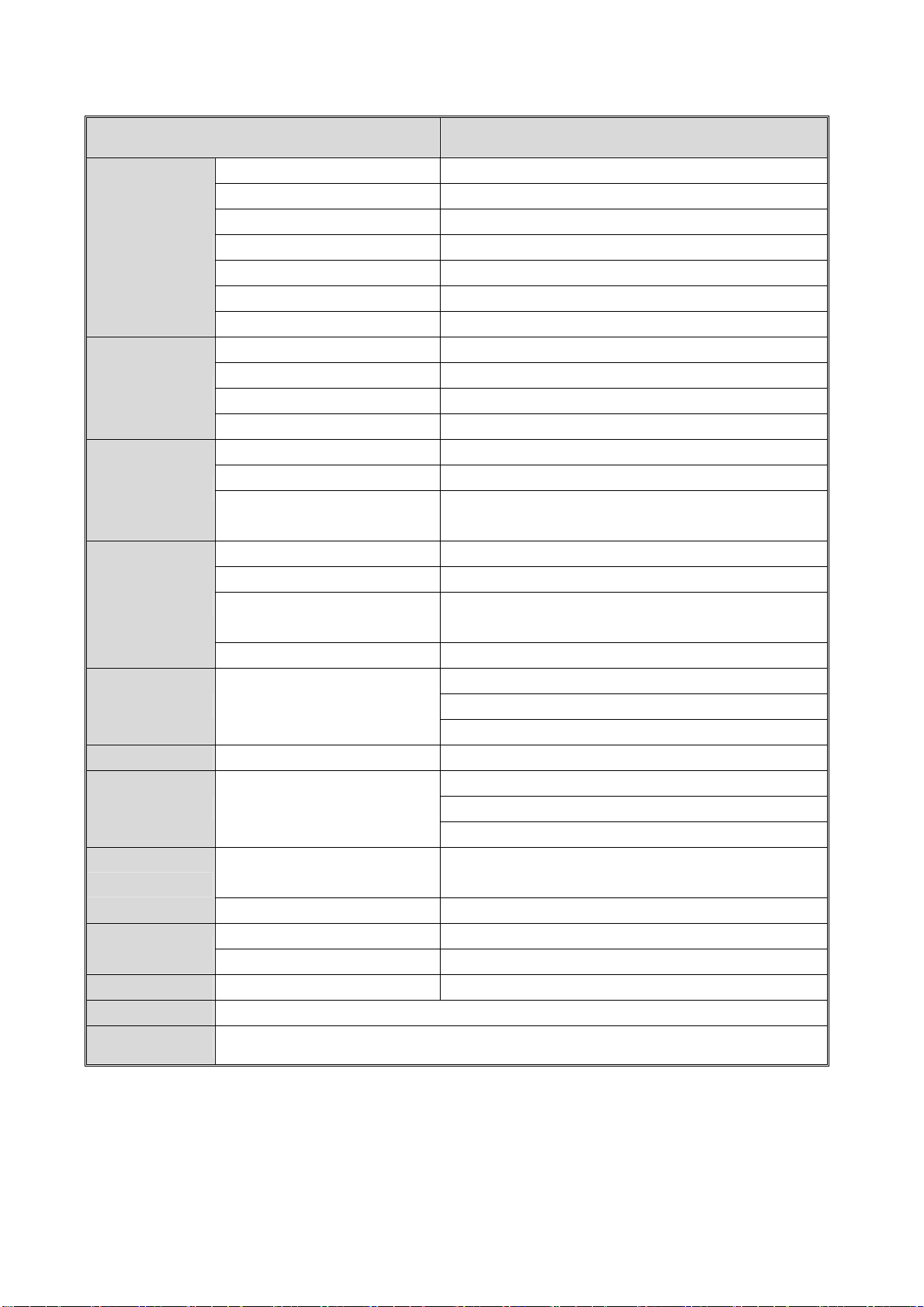
Accessories Remote Control, Batteries, AC cord, 15 Pin D-Sub Signal Cable
V27CMTT
ITEMS SPECIFICATION
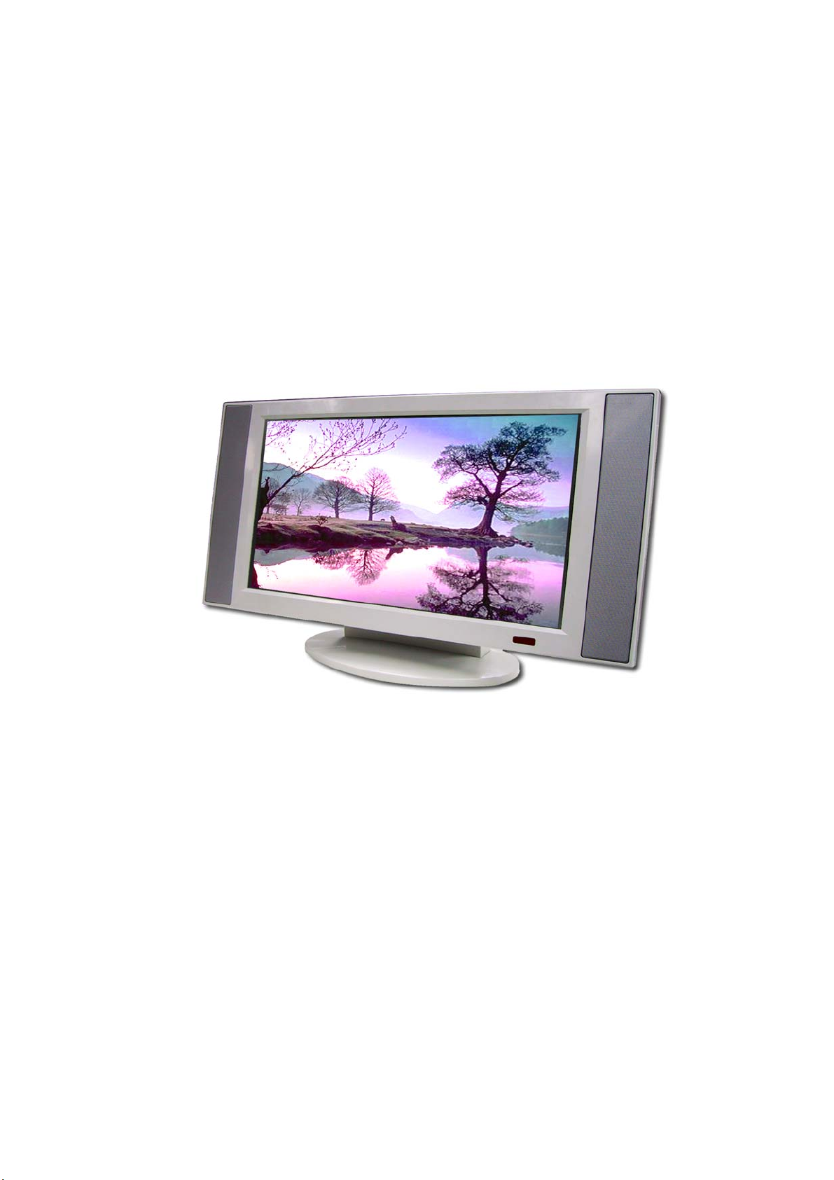
Screen size 27"wide TFT-LCD panel
Aspect Ratio 16:9
Resolution 1280 x 720(WXGA)
Contrast ratio 500:1 (typ)
Brightness 500cd/m2 (Typ)
Viewing Angle Over 170∘(Hor.) / 170∘(Vert.)
Display
OSD Language Chinese, English, French, German, Spanish
TV standard (CCIR) NTSC
TV Turning system PLL 181 Ch.
STEREO MTS+SAP
TV I/P
CATV 125 CH.
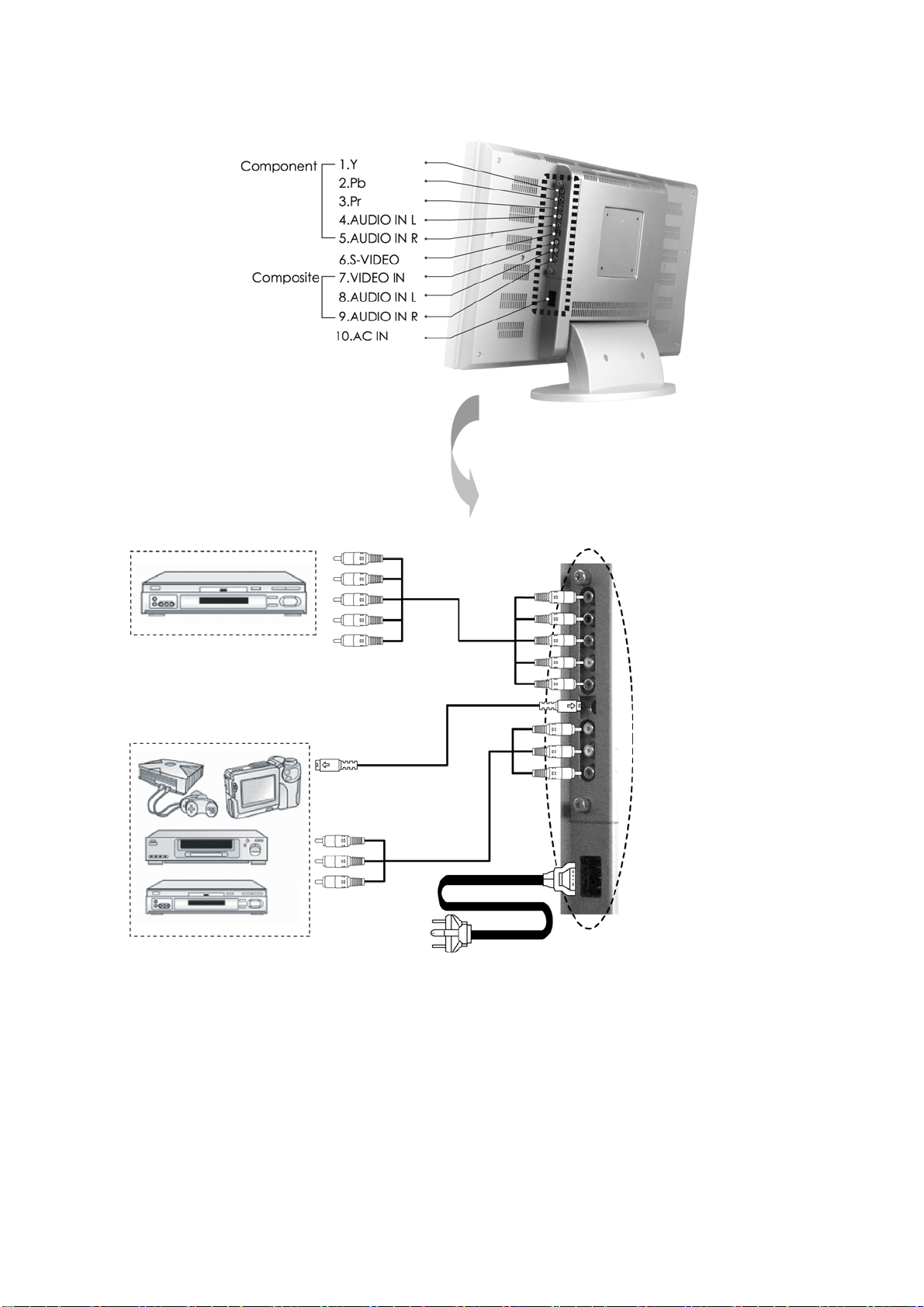
Composite Signal CVBS
Y, C Signal S-Video
Video I/P Composite Signal
Y, Pb/Cb, Pr/Cr HDTV system (720p, 1080i)
Signal I/P Analog:15 pin D-Sub Connector
PnP compatibility DDC / 2B
I/P Frequency Analog:FH:31.5KHz to 60KHz
F
V :56Hz to 75Hz
PC I/P
Recommended Analog:1024X768 (60Hz)
Audio 1:CVBS & S-Video
Audio 2:Y, Pb/Cb, Pr/Cr
Audio I/P Audio I/P:L/R x 3
Audio 3:PC
Video O/P Composite Signal TV only
Speaker (Build-in):10W+10W (rms)
3.5mm miniature stereo phone jack
Audio O/P Audio O/P:L/P x 3
Sound level output::500 mV(rms)
PIP,VOV,3D De-interlace, 3D
comb-filter ,V-Chip, C.C. Settings Yes
Other Functions
Aspect Ration Switching Normal → Periscope → Zoom →Full
Power Supply AC 110V ~ 240V, 50/60Hz
Power Power Consumption <140W
Panel Tilt Forwards/ Backwards /Rotation -5∘/ +20∘/ ± 180∘
Wight (net) 14.5Kg (Without Accessories)
Accessories Remote Control, Batteries, AC cord, 15 Pin D-Sub Signal Cable