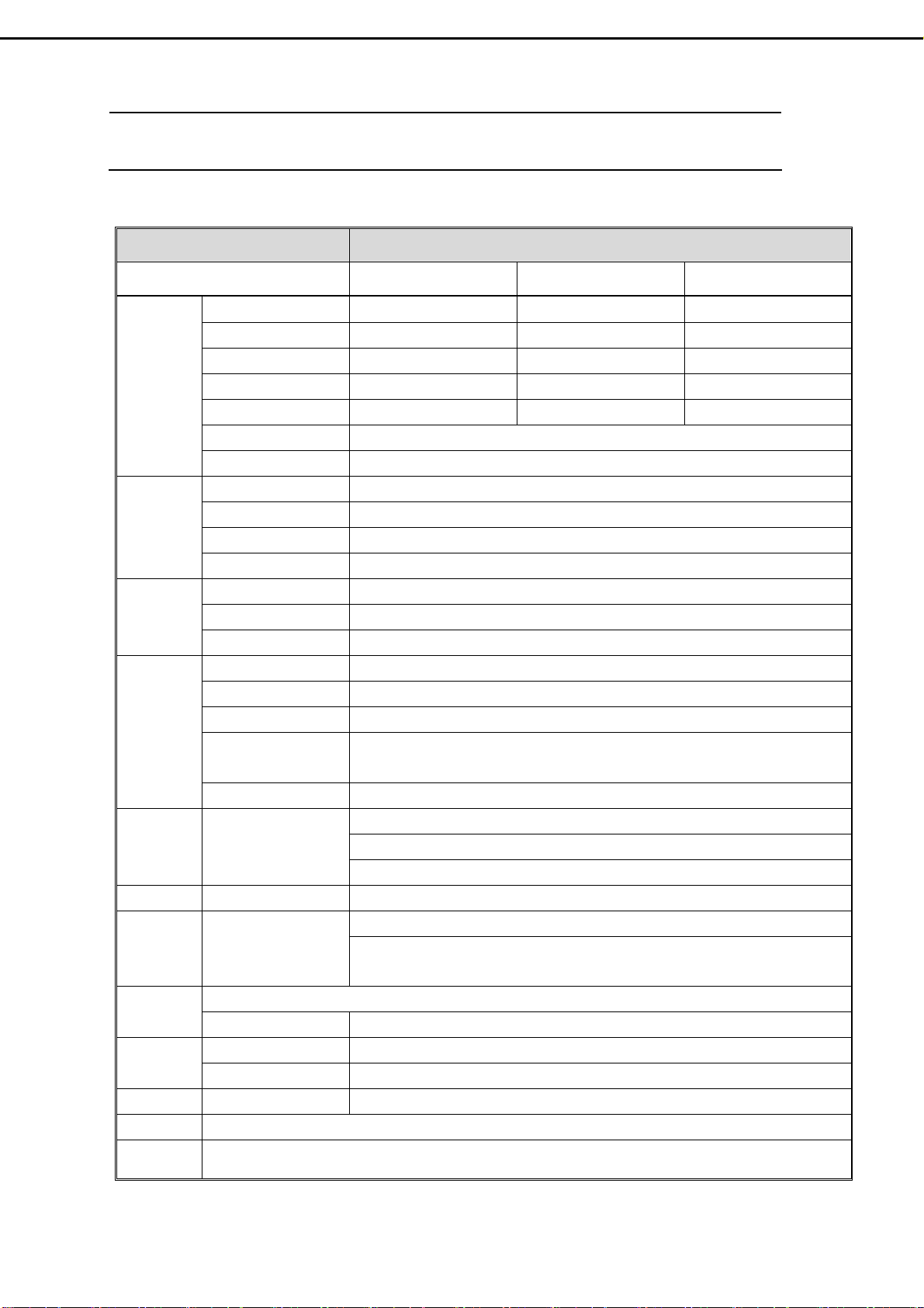
Tatung V32FLBB User manual

32” LCD-TV
Service Manual
N
NT
TS
SC
C
S
Sy
ys
st
te
em
m
V
V3
32
2F
FL
LB
BB
B
V
V3
32
2F
FC
CB
BB
B
V
V3
32
2F
FM
MB
BB
B
April 12,2005
Version1.0

Table of Contents
1. Safety and Precautions ……………………………………………1
2. Specifications.............................................…………………………3
3. Connection & Applications……….............................................….5
4. Controls Location …..................................................……….…….7
5. Remote Control.......................................................………………..8
6. Disassembly Instructions.....................……………….……….…..10
7. Block Diagram........................……………………………………..14
8. Troubleshooting…………...............................…………………….15
9. Factory Mode Setting ……………………………………………..20
10. Electronic Circuit Description...........…………………..…………21
11. Circuit Diagram.............................…………………………..…….24
12. PCB Layout.............................………………………………..……45
13. Electrical Spare Parts List …..........................……………………49
14. Mechanical Disassembly ...…......................……….…………….51
15. Mechanical Spare Parts List….........................................…………52
16. Firmware Update Procedure …………………………………….. 53

1. Safety and Precautions
1.1Safety Precautions :
1) Cleaning : Unplug the power cord from the AC outlet before cleaning the product.
Use a damp cloth to clean the product. Do not use liquid cleaners or aerosol
cleaners.
2) Heat sources : Keep the product away from heat sources such as radiators,
heaters, stoves and other heat-generating products (including amplifiers).
3) For added protection for this television equipment during a lightning storm, or
when it is left unattended and unused for long periods of time, unplug it from the
wall outlet and disconnect the antenna. This will prevent damage to the
equipment due to lightning and power-line surges.
4) If an outside antenna is connected to the television equipment, be sure the
antenna system is grounded so as to provide some protection against voltage
surges.
- 1 -
Example of antenna grounding
As per national electrical code
Antenna lead in wire
Antenna discharge
unit
Power service
grounding
Electrode system unit
Ground clamp
Electric service
equipment

5) An outside antenna system should not be located in the vicinity of overhead
power lines or other electric light or power circuits, or where it can fall into such
power lines or circuits. When installing an outside antenna system, extreme care
should be taken to keep from touching such power lines or circuits as contact
with them might be fatal.
6) Ventilation : The vents and other openings in the cabinet are designed for
ventilation. Do not cover or block these vents and openings since insufficient
ventilation can cause overheating and/or shorten the life of the product. Do not
place the product on a bed, sofa, rug or other similar surface, since they can
block ventilation opening. This product is not designed for built-in installation. Do
not place the product in an enclosed place such as a bookcase or rack, unless
proper ventilation is provided or the manufacturer's instructions are followed.
1.2 Product Safety Notice :
1) Many electrical and mechanical parts in this chassis provide special visual
safety protection. The protection afforded by them cannot necessarily be
obtained by using replacement components rated for higher voltage, wattage,
etc.
2) Before replacing any of these components, read the parts list manual carefully.
The use of substitute replacement parts, which do not have the same safety
characteristics, as specified in the parts list may create shock, fire or other
hazards.
1.3 Service Notes :
1) When replacing parts or circuit boards, wrap the wires around terminals before
soldering.
2) Keep wires away from high temperature components.
3) Keep cable and their shielding in their original position so as to reduce
interference.
- 2 -

2. Specifications
2.1 Specification :
ITEMS SPECIFICATION
Model Name V32FLBB V32FCBB V32FMBB
Screen size/ Supplier 31.51” / LG panel 31.51” / CPT panel 32.02”/ CMO panel
Aspect Ratio 16:9 16:9 16:9
Resolution 1366 x 768 (WXGA) 1366 x 768 (WXGA) 1366 x 768 (WXGA)
Contrast ratio 600:1 (typ.) 800:1 (typ.) 800:1 (typ.)
Brightness 500cd/m2(typ.) 500cd/m2(typ.) 550cd/m2(typ.)
Viewing Angle Over 170 (Hor.)∘/170 (Vert.)∘
Display
OSD Language Chinese , English, French , German , Spanish
TV standard (CCIR) NTSC
TV Turning system PLL 181 Ch.
STEREO MTS+SAP
TV I/P
CATV 125 CH.
Composite Signal CVBS x 2
Y, C Signal S-Video x 2
Video I/P
Composite Signal YPbPr x 2 (720p, 1080i HDTV Ready)
Analog I/P 15 pin D-Sub Connector
Digital I/P 24 pin DVI Connector
PnP compatibility DDC / 2B (Analog) , DVI 1.0 / HDCP 1.0 (Digital)
I/P Frequency FH :31.5KHz to 60KHz
FV :56Hz to 75Hz
PC I/P
Recommended 1024 x 768 (60Hz)
Audio 1:CVBS & S-Video x 2
Audio 2:YPbPr x2
Audio I/P Audio I/P:L/R
Audio 3:PC x1
Video O/P Composite Signal TV only
Speaker (Built-in):10W+10W (rms)
Audio O/P
Audio O/P:L/P
Sound level output
500 mV(rms) 3.5mm miniature stereo phone jack
PIP, PoP, 3D de-interlace, 3D comb-filter , V-Chip , C.C. SettingsOther
Functions Aspect Ratio Full →Normal →Zoom →Panoramic →Subtitle
Power Supply AC 110V ~ 240V, 50/60Hz
Power Power Consumption <180W
Dimension W x H x D 964.8mm x 580.4mm x 279.8mm
Wight (net) 22.2Kg (without Accessories)
Accessories Remote Control, Batteries, AC cord , DVI-D cable (optional), user’s manual.
- 3 -

2.2 PC Input preset timing table
Mode
No.
Mode
Resolution
H.Freq
(KHZ)
V. F r e q
(Hz)
H.Polarity
V.Polarity
Pixel
CLK
(MHZ)
Hor.
Total
Hor.
Display
H.Back
Porch
Hor.
Sync.
Width
Ve r.
Total
Ve r.
Display
V.Back
Porch
Ve r.
Sync
Width
1 VGA 70HZ
640*350
31.469
70.087
+
- 25.175 800 640 48 96 449 350 60 2
2 VGA 60HZ
640*480
31.469
59.941
-
- 25.175 800 640 48 96 525 480 32 2
3 VGA 72HZ
640*480
37.804
72.81
-
- 31.5 832 640 128 40 520 480 28 3
4 VGA 75HZ
640*480
37.5
75.0
-
- 31.5 840 640 120 64 500 480 16 3
5 SVGA 60HZ
800*600
31.156
56.25
+
+ 36.0 1024 800 128 72 625 600 22 2
6 SVGA 60HZ
800*600
37.879
60.317
+
+ 40.0 1056 800 88 128 628 600 23 4
7 SVGA 72HZ
800*600
48.077
72.188
+
+ 50.0 1040 800 64 120 666 600 23 6
8 SVGA 75HZ
800*600
46.875
75.0
+
+ 49.5 1056 800 160 80 625 600 21 3
9 XGA 60HZ
1024*768
48.363
60.004
-
- 65.0 1344 1024 160 136 806 768 29 6
10 XGA 70HZ
1024*768
56.476
70.069
-
- 75.0 1328 1024 144 136 806 768 29 6
11 XGA 75HZ
1024*768
60.023
75.029
+
+ 78.75 1312 1024 176 96 800 768 28 3
12 MAC VGA
640*480
35.0
66.667
-
- 30.24 864 640 96 64 525 480 39 3
13 MAC VGA
832*624
49.725
74.55
-
- 57.283 1152 832 224 64 667 624 39 3
14 MAC VGA
1280*768
47.73
60
-
- 80 1676 1280 198 136 795 768 23 3
15 WXGA
1280*720
45
60
+
+ 74.25 1650 1280 220 40 750 720 20 5
16 WXGA
1360*768
47.7
60 85.5 768
- 4 -

3. Connection & Applications
3.1 DVI port for HDCP Input
D-sub port for PC Input
3.2 DVI port for PC Input
D-sub port for Video Input
- 5 -

3.3 Video Expand card Connection
Audio O/P : The level of audio output cannot be changed by using the Volume, Treble,
and Bass controls on your TV. These connectors should be used with an
external amplifier that can be used to control the volume.
Video O/P : The main display must set to TV mode in order to use video out to record a
program using a VCR.
-6-
Subwoofer
Out
A/V Out

4. Control Location
Rear Side :
Before operating the LCD-TV or remote control, users must press MAIN POWER
switch to ON. The MAIN POWER switch is located at the bottom-left back of the
LCD-TV.
Front Side :
- 7 -

5. Remote Control
5.1 Remote Control :
- 8 -
VIDEO SWAP

5.2 Summary of Control Button
P
Po
ow
we
er
r
c
co
on
nt
tr
ro
ol
l
POWER button
Turn the TV on or off
Selecting the primary signal source
TV button Switch to TV mode
AV button Switch to AV mode (composite mode)
SV button Switch to S-Video mode
CV button Switch to CV mode (component :Y/Pb/Pr)
PC button Switch to PC mode (DVI or D-sub)
Menu Settings
MENU/ENTER button Display the on-screen menu or enter a sub-menu
EXIT/(INFORMATION) button Exit a menu or sub-menu. (Option: Display the current
channel or current primary signal source.)
UP,DOWN,LEFT,RIGHT buttons
Access to menu items
TV Changing Channels
CHANNEL△button Press Up to change the channel
CHANNEL▽button Press Down to change the channel
0~9 ; +100 button Select channels manually
RTN button Return to the previous viewed channel
Sound Control
VOLUME △button Increase volume level
VOLUME ▽button Decrease volume level
MUTE button Temporarily turn off audio
MTS button Cycle through Stereo, Mono or Separate Audio Program
(SAP) multi-channel sound services
TREBLE button Adjust treble level
BASS button Adjust bass level
SUBWOOFER button Enable/Disable the subwoofer
AUDIO SWAP button Exchange audio source of Main display and Sub display
PIP Control
ON/OFF button Enable/Disable PiP viewing window
Press again to make the sub display disappear
△/▽button Select PiP input source: TV→AV 1 →SV1→AV 2 →SV2
SIZE button Toggle PiP window size: 10%→20%…………90%→
100%
POSITION button Move the PiP window position
AUDIO SWAP button Exchange audio source of main display and PiP window
Other Function
SWAP button Exchange the main and Sub display
RESET button Return to the original factory settings.
ARC button (Aspect Ratio Control) PC mode:Set the picture mode to Full, Fill aspect, One
to one.
Video mode:Toggle the picture mode between normal
→Zoom→Full→Panoramic→Subtitle.
APC button (Automatic Picture Control) Toggle screen luminosity between Normal, Clear, Dark,
and Theater modes.
SLEEP button Select a pre-set time for automatic power down.
C.C. button Enable/Disabled closed captioning.
- 9 -

6. Disassembly Instructions
Face down the LCD-TV on a smooth plane with a soft material to protect the
panel faceplate.
A. Pull down two hooks to open the bottom cover.
B. Pull down two hooks to open the side cover.
- 10 -
C. Remove 4 screws and then take base assembly apart from the LCD-TV.
D. Loose 2 screws and pull up the Video Expand Card.

E. Remove 10 screws from the back cover.
F. Remove 1 screw from the back cover, and then take back cover apart from the LCD
TV
G. Remove 4 screws from the VESA wall-mounting bracket.
H. Remove the shield of power box.
H.’ Remove 2 screws, and then disconnect 3 wire assemblies from power box.
H.” Remove 1 screw from shield of main board, and 4 hexagonal screws from the DVI
and D-Sub connectors.
- 11-
G
G
H H’
H’’

I. Remove 8 screws from the Main board, and then take Main board apart from the
Panel bracket.
- 12-
J. Remove 6 screws from the Panel Bracket.

- 13 –
K. Take Panel Bracket apart from the Front Cover.

- 14 -
7. Block Diagram

8. Troubleshooting
8.1 Symptom Codes : ( for Call Center use )
CODE SYMPTOM COUNTERMEASURES
NP1 No Picture and No Sound
in TV mode.
zMake sure the Power cord and Antenna cable are
properly connected .
zMake sure the batteries in remote control are not
flat.
zPress the MAIN POWER switch to ON.
zSwitch to TV source by pressing TV button.
zSelect the correct signal source: “ANTENNA” or
“Cable- STD/ HRC/ IRC ” in OSD menu.
zRun “Auto Search ” in OSD menu.
NP2 No Picture and No Sound
in video mode.
zCheck the connection between the optional video
equipment and the TV.
zPress AV,SV,or CV button on the remote control
to select the corresponding video source.
NP3 TV is automatically turned
off.
zCheck if the “SLEEP” timer is activated .
zPress POWER button to turn on the TV once again.
NP4 Screen appears “totally
snowy” in TV mode. After
10 min., it turns off
automatically.
zCheck if Aerial cable is correctly connected.
zPress POWER button to turn on the TV again.
zPress CH Up/Down buttons to change channels.
No picture and and no Sound
NP5 Screen appears “No
Signal” in video mode.
After 10 min., it turns off
automatically.
zCheck if Video Cable is correctly connected and
Video Device is normal.
zPress POWER button to turn on the TV again.
zPress AV, S V, or CV button on the remote control to
select the corresponding video source.
PP1 Double Images / Ghosts If the TV suffers interference from signals reflecting from
mountains or buildings , double-pictures or Ghosts will
occur.
zAdjust the Antenna’s location and direction
zReplace it with one with better directionality.
zTurn off or disconnect the booster if it is in use , as
the booster may be inappropriate.
PP2 Snowy picture and noisy
Sound
If snow totally blocks out the picture , there may be a
problem with the Antenna or Antenna Cable .
zHave the TV and Antenna been connected
properly ? Has the Antenna cable been damaged ?
zIs the Antenna pointing in the right direction ?
zIs the Antenna itself faulty ?
zTry using a booster , as signal transmission may be
low.
PP3 Distorted picture and
noisy sound
zTurn off or disconnected the booster if it is in use ,
as broadcast signals may be too strong.
Poor Picture
PP4 Dotted Lines / Stripes
in the picture.
If the TV or Antenna suffers interference from other
equipment , stripes or noise may appear in the picture.
zKeep the TV away from noise sources such as
personal computer , amplifier , cars, motorcycles or
hair-dryers.
zIf the aerial suffers interference from a radio tower
or high-voltage wire , contact the local dealer.
-15-

CODE SYMPTOM COUNTERMEASURES
PP5 Stripe noise. zCheck the coaxial cable connected with the TV is not
oxidized
zDo not use 300 ohm twin lead cables as interference
may occur
zIt is recommended to use a 75 ohm coaxial cable
(not supplied) to get premium quality picture.
zKeep the aerial cable away from other connecting
cables.
PP6 No color, too light or too
dark
zAdjust the picture settings — APC, Brightness,
Contrast, Saturation , Color Temp.
zPress RESET button on remote control to return all
settings to factory settings.
Poor Picture
PP7 Poor picture on particular
channel.
zUse “Fine Tune” in OSD to manually adjust a
particular channel for optimal reception.
NS1 Good picture, no sound zMake sure the headphone is not connected. (option)
zCheck audio connections between Equipment &
LCD-TV.
zPress MUTE or VOL Up to cancel the muting.
No Sound or Noisy Sound
NS2 Noisy noise zMake sure that the antenna connected is 75 ohm
coaxial cable (not supplied) , not 300 ohm twin lead
cables .
zKeep the antenna cable away from other connecting
cables.
zPress MTS button to select “Mono” which will
reduce the noise.
zAdjust BASS or TREBLE properly on remote
control.
PC1 PC display is Not Full
Screen
zSelect “Auto” in OSD menu to optimize the image .
zIf executing Auto Image Adjust still can not achieve
full screen display, adjust “V. Position” and “H.
Position” in PC mode
PC2 Horizontal Noise or Color
pattern is not uniform
zSelect “Auto” in OSD menu to optimize the image .
zIf still no good , adjust “Phase” in OSD menu
PC3 “Out of Range”message zMaximum PC resolution supported is 1360x768
, so the screen will appear “Out of range” at higher
resolution.
zReduce the resolution to 1360x 768 from the PC.
Note The panel resolution is 1366x768, which is not a
standard timing, so it may not suit for all PC graphic
cards.
PC4 No Sound zMake sure PC audio Input is well connected.
PC
PC5 After “No Signal ” has
appeared on PC mode for
a while, the view
disappears and the LED
Indicator turns from
Green to”Amber” .
zPress any key on keyboard or move the mouse to
activate the PC , because the PC may go to power
saving status.
zCheck if the D-sub or DVI connector (Cable) is
disconnected or loose.
-16-

-16-
CODE SYMPTOM COUNTERMEASURES
RC1 Remote Control does not
work
zMake sure the batteries in remote control are not flat
zCheck the polarity of the batteries
zUse the remote control in the front of the TV or from
less than seven meters away.
zmake sure the Remote Sensor Window is not under
strong lighting.
RemoteControl
RC2 Can not change channels
with the remote control
zPress TV button to switch to TV mode.
PH1 Picture suddenly Stops
Responding or
abnormal.
zPress RESET button on remote control .
zUnplug and then plug the Power Cord of the TV from
the AC outlet.
Picture Halt / Abnormal
NG1 Issues can’t be solved. zIf the picture still abnormal, execute “ Clear
EEPROM”.
STEPS :
1. Press POWER Button to turn on LCD-TV.
2. Use right hand to press Ch▽ and Ch△ buttons
simultaneously, and keep pressing them (do not
release). Use left hand to turn the Main Power
Switch to OFF and then ON.
3. When UPDATE EEPROM appears on the screen,
release Ch ▽and Ch △buttons, which you’re
pressing.
Note : Remind user that every setting will return to
factory preset mode including PIN of parental
control (PIN : 000000), channel setting.
Note
1. CV and PC modes, including D-sub and DVI, are not available on Sub-display of PIP and
PoP.
2. TV mode is note available on side by side display.
3. If Main-display is CV and Sub-display is ON, de-interlace function is not available for CV.
-17-

8.2 Flow Chart : ( for Repair Center use )
(1) Power fair :
- 18 -
3~5V
Check
I12 #4
No
Yes
否
0~0.5V
Replace I12
Yes
No
No picture
No picture
Clear
EEPROM
Picture
appears
Replace
I34
(
MCU
)
Send to
factory
for repair.
No picture
Yes
Check if sources are
connected correctly.
Re-plug U901A to
connector CN3
(12P) , and then
check volta
g
es a
g
ain
Check if Inverter is
connected correctly.
Yes
No
Is panel wire P015A
connected with P15
correctly?
Re-
plug
No
否
否
Yes
Yes
Yes
Does the LED
light up?
Does LED light
Amber?
Restart signal to
ensure H. V. sync.
are not absent
End
Is it entering screen
protection (or power
saving) on PC mode?
No
Picture
appears
Picture
appears
Replace Main
Board PWB-0713
No
No
No
Yes
Re-
plug
No picture
No
picture
No
picture
No
picture
Re-
plug
No
Yes Yes
Picture
appears
No
Yes
Is the Voltage at
I12 #8 = 5V?
No
No picture
No picture
Picture
appears
No picture
Replace Inverter.
Check connector CN3 (12P) and
Wire U901A : Red wire = 24V ,
Blue & White wires > 2.5V
Is connector CN3
(12P) on Power
Module connected
correctly?
Is Backlight
lit?
Re-
plug
No picture
Appears
Replace Power
Module (.PB01)
Picture
appears
Picture
appears
Picture
appears
Picture
appears
Picture
appears
Clea
r
EEPROM
End
This manual suits for next models
2
Table of contents
Other Tatung LCD TV manuals