tau VLED User manual
LA RIPRODUZIONE, DIVULGAZIONE, DISTRIBUZIONE E OGNI ALTRA ATTIVITA' DEL PRESENTE DISEGNO O PARTE
DI ESSO E' VIETATA SENZA NOSTRA ESPLICITA AUTORIZZAZIONE SCRITTA ED E' TUTELATA DALLE LEGGI VIGENTI.
CLASSE "B"
CLASSE "A"
CLASSE "C"
DA > 3
A 10mm
DA > 10
A 25mm
DA > 80
A 200mm
DA 0
A 3mm
DA > 200
A 400mm
DA > 400
A 800mm
OLTRE
800mm
DA > 25
A 80mm
0,05 0,08 0,14 0,20 0,26 0,32 0,40 0,48
0,10 0,15 0,21 0,30 0,40 0,57 0,65 0,85
0,02 0,035 0,05 0,07
5
0,10 0,14 0,17 0,20
Classe di tolleranza rispetto alla dimensione nominale in " + " o " - " espressa in "mm"
NOME MODELLO TIPO MODELLO STATO MATERIALE
SOSTITUITO DA SOSTITUISCE IL
NORMATIVE
NOTE GENERICHE
DISEGNATO DA
MODIFICATO DA
VERIFICATO DA
APPROVATO DA
RICHIESTO DA
NOTE DI MODIFICA
TRATTAMENTO FINITURA
MATERIALE PESO
CODICE REVISIONE CODICE STAMPO
DESCRIZIONE
A
B
C
D
E
F
A
B
C
D
E
F
1234
1234
SCALA
DATA
DATA
DATA
DATA
DATA
M.D. 14/06/18
P.M. 12/06/18
P.M. 30/08/18
- 00-00-00
- 00-00-00
A4
S-900VLED00040 02
S-900VLED00040 PART -
STAFFA DI FISSAGGIO A MURO LAMPEGGIANTE VLED
- -
-
ABS 48.011 g
Foglio: 3 di 3
- -
APPORTATO MODIFICHE RICHIESTE DA STAMPISTA
INSERITO INDICAZIONE FINITURA
B
-
-
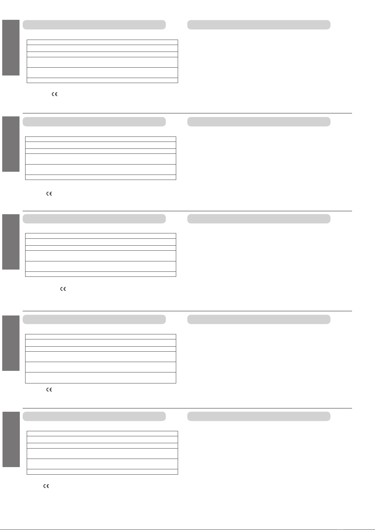
45 mm
LA RIPRODUZIONE, DIVULGAZIONE, DISTRIBUZIONE E OGNI ALTRA ATTIVITA' DEL PRESENTE DISEGNO O PARTE
DI ESSO E' VIETATA SENZA NOSTRA ESPLICITA AUTORIZZAZIONE SCRITTA ED E' TUTELATA DALLE LEGGI VIGENTI.
CLASSE "B"
CLASSE "A"
CLASSE "C"
DA > 3
A 10mm
DA > 10
A 25mm
DA > 80
A 200mm
DA 0
A 3mm
DA > 200
A 400mm
DA > 400
A 800mm
OLTRE
800mm
DA > 25
A 80mm
0,05 0,08 0,14 0,20 0,26 0,32 0,40 0,48
0,10 0,15 0,21 0,30 0,40 0,57 0,65 0,85
0,02 0,035 0,05 0,
0
7
5
0,10 0,14 0,17 0,20
Classe di tolleranza rispetto alla dimensione nominale in " + " o " - " espressa in "mm"
NOME MODELLO TIPOMODELLO STATOMATERIALE
SOSTITUITO DA SOSTITUISCEIL
NORMATIVE
NOTE GENERICHE
DISEGNATO DA
MODIFICATO DA
VERIFICATO DA
APPROVATO DA
RICHIESTO DA
NOTE DI MODIFICA
TRATTAMENTO FINITURA
MATERIALE PESO
CODICE REVISIONE CODICESTAMPO
DESCRIZIONE
A
SCALA
DATA
DATA
DATA
DATA
DATA
B
C
D
E
F
1
G
23456789
123456789
M.D. 08/05/18
P.M. 08/05/18
- 00-00-00
- 00-00-00
- 00-00-00
A0
LAMPEGGIANTE_VER24_SMONTAGGIO_100
LAMPEGGIANTE_VER24_SMONTAGGIO_1ASSEM -
VERSIONE 20 MAGGIORATO
- -
1/1
472551229.954 g
Foglio: 1 di 1
- -
-
-
B
-
-
LA RIPRODUZIONE, DIVULGAZIONE, DISTRIBUZIONE E OGNI ALTRA ATTIVITA' DEL PRESENTE DISEGNO O PARTE
DI ESSO E' VIETATA SENZA NOSTRA ESPLICITA AUTORIZZAZIONE SCRITTA ED E' TUTELATA DALLE LEGGI VIGENTI.
CLASSE "B"
CLASSE "A"
CLASSE "C"
DA > 3
A 10mm
DA > 10
A 25mm
DA > 80
A 200mm
DA 0
A 3mm
DA > 200
A 400mm
DA > 400
A 800mm
OLTRE
800mm
DA > 25
A 80mm
0,05 0,08 0,14 0,20 0,26 0,32 0,40 0,48
0,10 0,15 0,21 0,30 0,40 0,57 0,65 0,85
0,02 0,035 0,05 0,
07
5
0,10 0,14 0,17 0,20
Classe di tolleranza rispetto alla dimensione nominale in " + " o " - " espressa in "mm"
NOME MODELLO TIPO MODELLO STATO MATERIALE
SOSTITUITO DA SOSTITUISCE IL
NORMATIVE
NOTE GENERICHE
DISEGNATO DA
MODIFICATO DA
VERIFICATO DA
APPROVATO DA
RICHIESTO DA
NOTE DI MODIFICA
TRATTAMENTO FINITURA
MATERIALE PESO
CODICE REVISIONE CODICE STAMPO
DESCRIZIONE
A
SCALA
DATA
DATA
DATA
DATA
DATA
B
C
D
E
F
123457 68
A
B
C
D
E
F
123457 68
- 00-00-00
- 00-00-00
- 00-00-00
- 00-00-00
- 00-00-00
A1
MANUALE_LAMPEGGIANTE_VER2400
MANUALE_LAMPEGGIANTE_VER24 ASSEM -
-
- -
1/1
1968218748.375 g
Foglio: 1 di 1
- -
-
-
B
-
-
LA RIPRODUZIONE, DIVULGAZIONE, DISTRIBUZIONE E OGNI ALTRA ATTIVITA' DEL PRESENTE DISEGNO O PARTE
DI ESSO E' VIETATA SENZA NOSTRA ESPLICITA AUTORIZZAZIONE SCRITTA ED E' TUTELATA DALLE LEGGI VIGENTI.
CLASSE "B"
CLASSE "A"
CLASSE "C"
DA > 3
A 10mm
DA > 10
A 25mm
DA > 80
A 200mm
DA 0
A 3mm
DA > 200
A 400mm
DA > 400
A 800mm
OLTRE
800mm
DA > 25
A 80mm
0,05 0,08 0,14 0,20 0,26 0,32 0,40 0,48
0,10 0,15 0,21 0,30 0,40 0,57 0,65 0,85
0,02 0,035 0,05 0,07
5
0,10 0,14 0,17 0,20
Classe di tolleranza rispetto alla dimensione nominale in " + " o " - " espressa in "mm"
NOME MODELLO TIPO MODELLO STATO MATERIALE
SOSTITUITO DA SOSTITUISCE IL
NORMATIVE
NOTE GENERICHE
DISEGNATO DA
MODIFICATO DA
VERIFICATO DA
APPROVATO DA
RICHIESTO DA
NOTE DI MODIFICA
TRATTAMENTO FINITURA
MATERIALE PESO
CODICE REVISIONE CODICE STAMPO
DESCRIZIONE
A
B
C
D
E
F
A
B
C
D
E
F
1234
1234
SCALA
DATA
DATA
DATA
DATA
DATA
I.D. 20/02/19
P.M. 20/02/19
- 00-00-00
- 00-00-00
- 00-00-00
A4
CABLAGGIO_VLED 00
CABLAGGIO_VLED ASSEM -
CABLAGGIO V-LED
- -
-
22299.647 g
Foglio: 1 di 1
- -
-
-
B
-
-
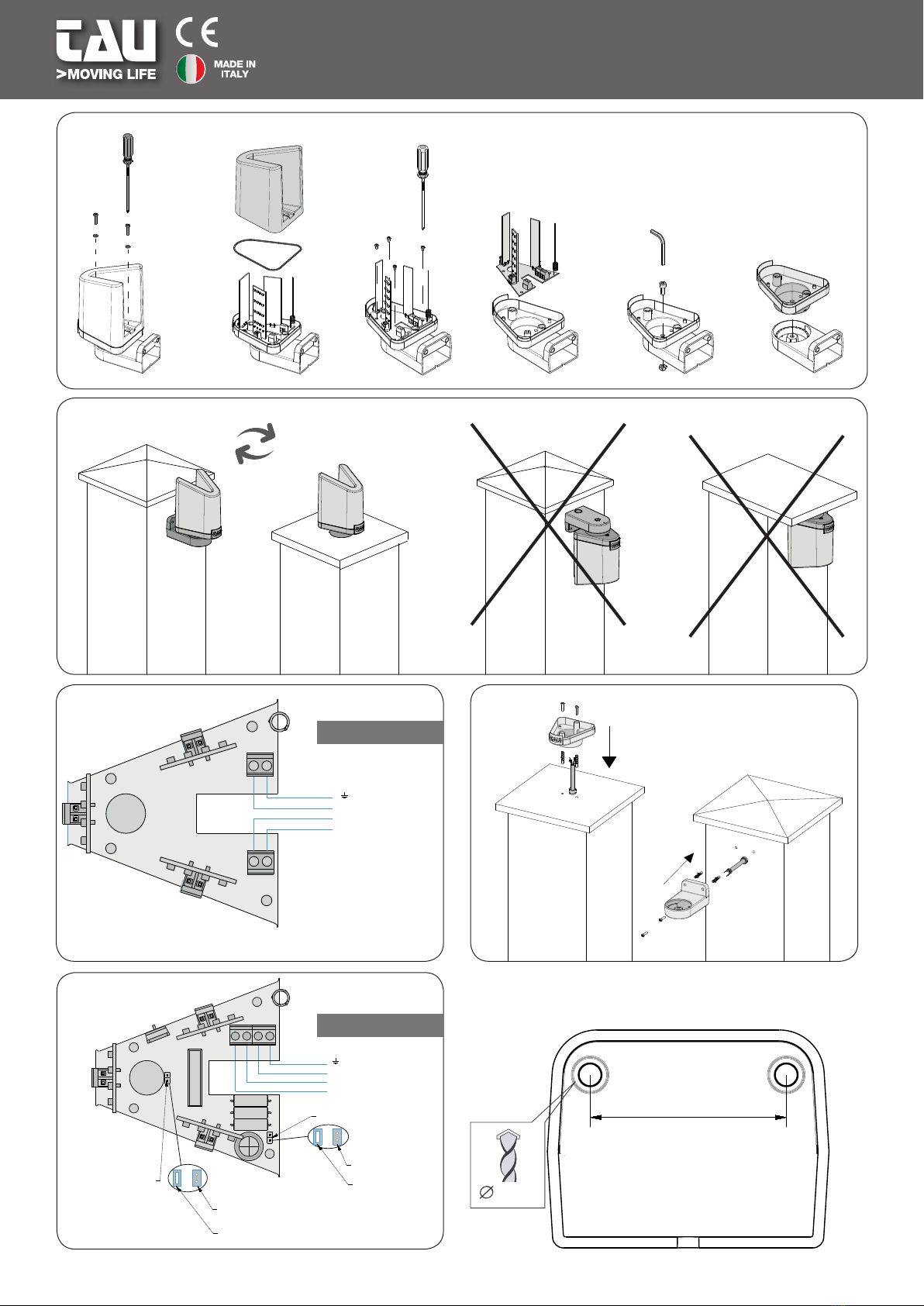
AERIAL (GROUND)
AERIAL (SIGNAL)
+ 12/24 V DC
- 12/24 V DC
LA RIPRODUZIONE, DIVULGAZIONE, DISTRIBUZIONE E OGNI ALTRA ATTIVITA' DEL PRESENTE DISEGNO O PARTE
DI ESSO E' VIETATA SENZA NOSTRA ESPLICITA AUTORIZZAZIONE SCRITTA ED E' TUTELATA DALLE LEGGI VIGENTI.
CLASSE "B"
CLASSE "A"
CLASSE "C"
DA > 3
A 10mm
DA > 10
A 25mm
DA > 80
A 200mm
DA 0
A 3mm
DA > 200
A 400mm
DA > 400
A 800mm
OLTRE
800mm
DA > 25
A 80mm
0,05 0,08 0,14 0,20 0,26 0,32 0,40 0,48
0,10 0,15 0,21 0,30 0,40 0,57 0,65 0,85
0,02 0,035 0,05 0,07
5
0,10 0,14 0,17 0,20
Classe di tolleranza rispetto alla dimensione nominale in " + " o " - " espressa in "mm"
NOME MODELLO TIPO MODELLO STATO MATERIALE
SOSTITUITO DA SOSTITUISCE IL
NORMATIVE
NOTE GENERICHE
DISEGNATO DA
MODIFICATO DA
VERIFICATO DA
APPROVATO DA
RICHIESTO DA
NOTE DI MODIFICA
TRATTAMENTO FINITURA
MATERIALE PESO
CODICE REVISIONE CODICE STAMPO
DESCRIZIONE
A
B
C
D
E
F
A
B
C
D
E
F
1234
1234
SCALA
DATA
DATA
DATA
DATA
DATA
I.D. 20/02/19
P.M. 20/02/19
- 00-00-00
- 00-00-00
- 00-00-00
A4
CABLAGGIO_VLED-AT 00
CABLAGGIO_VLED-AT ASSEM -
CABLAGGIO VLED-AT
- -
-
27025.334 g
Foglio: 1 di 1
- -
-
-
B
-
-
AERIAL (GROUND)
AERIAL (SIGNAL)
~ 115/230 V AC
~ 115/230 V AC
JUMPER J1
230 Vac
115 Vac
JUMPER J2
FLASHING
FIXED
5 mm
360°
VLED
TAU srl - Via Enrico Fermi, 43 - 36066 Sandrigo (VI) - Italy
Tel +39 0444 750190 - Fax +39 0444 750376
www.tauitalia.com
D-MNL0VLED 13-12-19 - Rev.01
VLED / VLED-O
VLED-AT/VLED-ATO
Fissaggio verticale
Vertical xing
Vertikalen Oberäche
Montage vertical
Fijación vertical
1. LAMPEGGIANTE
Caratteristiche tecniche
VLED / VLED-O VLED-AT/VLED-ATO
Alimentazione 12-24 V DC 115-230 V AC
Assorbimento 120 mA 50 mA
Potenza lampada 1,5 W (12 V DC) -
3 W (24 V DC)
12 W (230 V AC) -
6 W (115 V AC)
Flusso luminoso Led 300 lumen (white) -
170 lumen (orange)
300 lumen (white) -
170 lumen (orange)
Grado di protezione IP44
1. FLASHING LlGHT
Technical features
VLED / VLED-O VLED-AT/VLED-ATO
Power 12-24 V DC 115-230 V AC
Absorption 120 mA 50 mA
Lamp power 1,5 W (12 V DC) -
3 W (24 V DC)
12 W (230 V AC) -
6 W (115 V AC)
Led light output 300 lumen (white) -
170 lumen (orange)
300 lumen (white) -
170 lumen (orange)
Protection level IP44
1. BLlNKLAMPE
Technlsche Merkmale
VLED / VLED-O VLED-AT/VLED-ATO
Einspeisung 12-24 V DC 115-230 V AC
Entnahme 120 mA 50 mA
Versorgungder Lampe 1,5 W (12 V DC) -
3 W (24 V DC)
12 W (230 V AC) -
6 W (115 V AC)
Lichtstrom Led 300 lumen (white) -
170 lumen (orange)
300 lumen (white) -
170 lumen (orange)
Schutzart IP44
1. CLlGNOTANT
Caracteristiques techniques
VLED / VLED-O VLED-AT/VLED-ATO
Alimentation 12-24 V DC 115-230 V AC
Absorption 120 mA 50 mA
Puissance lampe 1,5 W (12 V DC) -
3 W (24 V DC)
12 W (230 V AC) -
6 W (115 V AC)
Flux lumineux Led 300 lumen (white) -
170 lumen (orange)
300 lumen (white) -
170 lumen (orange)
Degré de protection IP44
1. INDICADOR INTERMITENTE
Caracteristícas tecnícas
VLED / VLED-O VLED-AT/VLED-ATO
Alimentación 12-24 V DC 115-230 V AC
Absorción 120 mA 50 mA
Potencia lámpara 1,5 W (12 V DC) -
3 W (24 V DC)
12 W (230 V AC) -
6 W (115 V AC)
Flujo luminoso Led 300 lumen (white) -
170 lumen (orange)
300 lumen (white) -
170 lumen (orange)
Grado de protección IP44
2. INSTALLAZIONE
1. Scegliere la posizione del lampeggiante, in modo che si trovi in prossimità
del cancello, facilmente visibile. Il lampeggiante può essere ssato su una
supercie orizzontale o verticale, e può essere ruotato sull’asse orizzontale
della base a 360° per consentire la massima visibilità.
Altre modalità di ssaggio non sono consentite.
2. Predisporre i cavi necessari all’alimentazione e all’antenna.
3. Fissare il supporto a parete o in piano con viti e tasselli adeguati.
4. Collegare i cavi alla scheda secondo lo schema.
5. Reinserire la scheda nell’apposita sede, quindi richiudere il lampeggiante.
J1 Inserito: alimentazione 230 V AC
J1 Disinserito: alimentazione 115 V AC
J2 Inserito: centrale di comando con lampeggio incorporato
J2 Disinserito: centrale di comando SENZA lampeggio incorporato
2. INSTALLATION
1. Choose the position of the ashing light, so that it is near the gate and clearly
visible. The ashing light can be installed on a vertical or horizontal surface
and can be rotated by 360° on the horizontal axis of its base to ensure the
maximum visibility.
No other xing solutions are allowed.
2. Arrange the cables required for the power supply and the aerial.
3. Fix the support to the wall or on a plain surface through proper screws and plugs.
4. Connect the cables to the control board according to the scheme.
5. Place the control board in its position and close the ashing light.
J1 on: 230 V AC power supply
J1 o: 115 V AC power supply
J2 on: control board with built-in ashing
J2 o: control board WITHOUT built-in ashing
2. INSTALLATION
1. Wählen Sie die Position des Blinklichts so, dass es sich in der Nähe des Tors
bendet und gut sichtbar ist. Das Blinklicht kann auf einer horizontalen oder
vertikalen Oberäche befestigt werden und kann um 360 ° um die horizontale
Achse der Basis gedreht werden, um maximale Sichtbarkeit zu ermöglichen.
Andere Befestigungsmethoden sind nicht zulässig.
2. Bereiten Sie die erforderlichen Kabel für die Stromversorgung und die Antenne vor.
3. Befestigen Sie die Halterung mit geeigneten Schrauben und Dübeln an der
Wand oder im ache.
4. Verbinden Sie die Kabel mit der Steuereinheit gemäß Diagramm.
5. Setzen Sie die Karte wieder in das Gehäuse ein und schließen Sie das Blitzlicht.
J1 Eingefügt: 230 V AC-Stromversorgung
J1 Aus: 115 V AC Stromversorgung
J2 eingefügt: Steuereinheit mit eingebautem Blinklicht
J2 deaktiviert: Steuereinheit OHNE eingebautes Blinklicht
2. INSTALLATION
1. Choisir la place de la lampe clignotante an qu’elle soit à côté du portail et
aisément visible. La lampe clignotante peut être installée sur une surface
horizontale ou verticale et peut être tournée sur l’axe horizontal de sa base
de 360° pour en assurer la visibilité maximale.
Tout autre mode d’installation n’est pas autorisé.
2. Préparer les câbles nécessaires à l’alimentation électrique et à l’antenne.
3. Fixer le support au mur ou sur une surface plate par des vis et des chevilles adaptés.
4.Relier les câbles à la centrale de commande selon le schéma.
5. Introduire la centrale de commande dans sa place et refermer la lampe clignotante.
J1 activé: alimentation 230 V AC
J1 désactivé: alimentation 115 V AC
J2 activé: centrale de commande avec clignotement intégré
J2 désactivé: centrale de commande SANS clignotement intégré
2. INSTALACIÓN
1. Elija la posición de la luz intermitente, de modo que esté cerca de la puerta,
fácilmente visible. La luz intermitente se puede jar en una supercie
horizontal o vertical, y se puede girar en el eje horizontal de la base a 360°
para permitir la máxima visibilidad.
Otros métodos de jación no están permitidos.
2. Prepare los cables necesarios para la fuente de alimentación y la antena.
3. Fije el soporte a la pared o plano con tornillos y tapones adecuados.
4. Conecte los cables a la placa de acuerdo con el diagrama.
5. Vuelva a insertar la tarjeta en su alojamiento, luego cierre la luz intermitente.
J1 insertado: alimentación 230 V AC
J1 desconectado: alimentación 115 V AC
J2 insertado: central de mando con intermitencia incorporada
J2 desconectado: central de mando SIN intermitencia incorporada
Declaration TAU srl declares that this device complies with the essential requirements
and other relevant provisions established in Directives 2006/95/EC and 2004/108/EC.
A true copy of the declaration of conformity is available upon request.
Herstellererklärung TAU srl bestätigt, dass dieses Gerät den grundlegenden Anforde-
rungen und entsprechenden Bestimmungen der Richtlinien 2006/95/EG und 2004/108/
EG entspricht. Auf Anfrage ist eine dem Original entsprechende Kopie der Konformität-
serklärung verfügbar.A true copy of the declaration of conformity is available upon request.
Déclaration TAU srl déclare que ce dispositif est conforme aux exigences essentielles et
aux dispositions pertinentes établies par les directives 2006/95/CE et 2004/108/CE.
La copie conforme à l’original de la déclaration de conformité est disponible sur demande.
Directiva TAU srl declara que este dispositivo cumple con los requisitos esenciales
y con las demás disposiciones pertinentes establecidas por las Directivas 2006/95/CE y
2004/108/CE.
A petición está disponible la copia conforme al original de la declaración de conformidad.
Dichiarazione TAU srl dichiara che questo dispositivo è conforme ai requisiti essenziali
e alle altre disposizioni pertinenti stabilite dalle direttive 2006/95/CE e 2004/108/CE. Su
richiesta è disponibile la copia conforme all’originale della dichiarazione di conformità.
italianoenglish
deutsch
francais
español
This manual suits for next models
3
Popular Outdoor Light manuals by other brands

Feiss
Feiss OL3403 Assembly instructions

Schrack Technik
Schrack Technik ZELDA LED Round Large Series Assembly instructions

Signature Hardware
Signature Hardware DILLING installation instructions

Philips
Philips 168244716 Specifications

nordlux
nordlux NESTOR installation instructions

Kichler Lighting
Kichler Lighting Hone 59138B installation instructions

RAB
RAB WPLED13N installation instructions

LIGMAN
LIGMAN GA-31912 installation manual

Outsunny
Outsunny 867-129V00 Assembly instruction

AMP Lighting
AMP Lighting AAL-1019-4 Series Installation & maintenance guide

flower POWER
flower POWER 9004487709204 user manual

Landa
Landa IM 5000AS Series quick start guide


