Taylor SYSTEM CD200 SERIES User manual

TAYLOR
STUDWELDING
SYSTEMS LIMITED.
OPERATING MANUAL
FOR
SYSTEM CD200 SERIES
COMPACT CAPACITOR DISCHARGE
STUDWELDING EQUIPMENT

INDEX
PAGE CONTENT
1 GENERAL INFORMATION
3 INTRODUCTION
4 EQUIPMENT SCHEDULE
5 EXTERIOR FEATURES
7 SAFETY
10 SETTING UP AND WELDING
16 WELD SETTINGS
27 LOCATION METHODS
28 WELD ASSESSMENT / TESTING
29 CONTACT PISTOL EXPLOSION AND PARTS LIST
31 MARK V LIFT GAP PISTOL EXPLOSION AND PARTS LIST
34 CONTROLLER EXPLOSION AND PARTS LIST
37 CIRCUIT SCHEMATIC
38 AVAILABLE ACCESSORIES
45 EC DECLARATION OF CONFORMITY
46 EMC CERTIFICATE
CD200 OP. MAN
EDITION 1A

GENERAL INFORMATION
MANUFACTURERS DETAILS
TAYLOR STUDWELDING SYSTEMS LIMITED
COMMERCIAL ROAD
DEWSBURY
WEST YORKSHIRE
WF13 2BD
ENGLAND
TELEPHONE : +44 (0)1924 452123
FACSIMILE : +44 (0)1924 430059
e-mail : info@taylor-studwelding.com
TECHNICAL TEL : +44 (0)1924 487703
SALES TEL : +44 (0)1924 487701
PURPOSE AND CONTENT OF THIS MANUAL
This manual has been written for :
The operator of the welding machine.
The personnel of the final customer responsible for the installation
and operation of the machine.
This manual contains information on :
Installation and connection
Operation.
Technical data.
Spare parts.
Accessories.
1

GENERAL INFORMATION
FURTHER INFORMATION
Should you require additional technical information, please contact us
directly (details on page 1) or our local agent / distributor (details of agents
etc. can be obtained from us).
This manual contains important information which is a pre-requisite for
safe operation of the equipment. The operating personnel must be able to
consult this manual. In the interests of safety, make this manual available to
your personnel in good time.
If the equipment is sold / passed on, please hand over this manual to
the new owner. Please immediately inform us of the name and address of
the new owner, in case we need to contact him regarding the safety of the
device.
Please read this manual carefully before installation of the
machine.
Please especially observe the safety instructions.
2

INTRODUCTION
INTRODUCTION
The complete range of Taylor Studwelding Systems Capacitor Discharge
units are compact, portable Stud Welding equipment's. The units are specifi-
cally designed to enable a small diameter range of ferrous and non-ferrous
weld studs to be welded to light gauge, self-finish or pre-coated materials,
in most cases with little or no reverse marking.
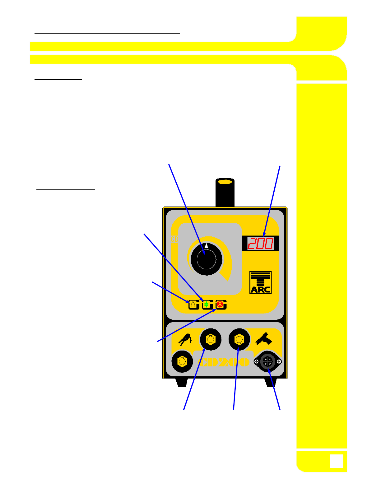
The equipment consists of a control unit, a welding pistol and the nec-
essary interconnecting cables and accessories (see page 4 for the equip-
ment schedule).
THE PROCESS
Capacitor Discharge stud welding is a form of welding in which the en-
ergy required for the welding process is derived from a bank of charged ca-
pacitors. This stored energy is discharged across the gap between the two
surfaces to be welded as they are propelled towards each other. The arc pro-
duced heats the two surfaces, melting a thin film of metal on each surface
and the propelling force closes the gap between the two faces, thus forming
a weld.
In contact welding the stud to be welded is forced by spring pressure on
to the plate. At this point the arc gap between the two components is main-
tained by a small pip on the welding face of the stud. On initiation of the
high current pulse from the capacitors, this pip vaporises and an arc is
drawn between the work piece and the stud. The heat from this arc melts the
base of the stud and the area of the work piece directly beneath the stud,
whilst the spring pressure from the pistol accelerates the towards the work
piece. Within 3 to 4 milliseconds the stud hits the work piece and the arc is
extinguished. The kinetic energy contained in the moving stud and the re-
maining spring pressure, forge the molten parts together to form a weld.
3

EQUIPMENT SCHEDULE
EQUIPMENT
No. OFF DESCRIPTION PART No.
1 SYSTEM CD200 - 66 CONTACT 99-100-110
COMPLETE
or SYSTEM CD200 - 66 LIFT GAP 99-100-114
COMPLETE
or SYSTEM CD200 - 99 CONTACT 99-100-111
COMPLETE
or SYSTEM 200CD - 99 LIFT GAP 99-100-115
COMPLETE
or SYSTEM CD200 - 132 CONTACT 99-100-119
COMPLETE
1 CD CONTACT PISTOL 99-100-020
or CD LIFT GAP PISTOL 99-100-023
2 EARTH CABLE ASSEMBLY 99-100-031
ACCESSORIES (SUPPLIED WITH EQUIPMENT)
No. OFF DESCRIPTION PART No.
1 CHUCK KEY 79-101-111
ACCESSORIES (NOT SUPPLIED WITH EQUIPMENT)
See pages 38 to 44 of this manual for a selection of accessories available
from either your local stockist or the manufacturer.
4

EXTERNAL FEATURES
FRONT PANEL
1 WELDING VOLTAGE SELECTOR KNOB
2 WELDING VOLTAGE DIGITAL DISPLAY
3 WELDING EARTH PANEL CONNECTIONS
4 WELDING PISTOL PANEL CONNECTION
5 WELDING PISTOL CONTROL SOCKET
1 2
INDICATOR LED's
1 READY (GREEN) Indicates
that the capacitor bank is
charged to the pre-selected
value and is ready to weld.
2 CHARGING (YELLOW)
Indicates that the unit is in the
process of charging the
capacitors to the pre-selected
voltage.
3 RESET (RED) Indicates
that the unit safety circuit has
tripped. To reset the unit,
switch off the mains switch,
wait between 5 and 30 seconds
then switch back on.
3 4 5
5

EXTERNAL FEATURES
REAR PANEL
SERIAL / RATING PLATE
CASING VENTILATION HOLES
VENTRAL HOLES NOT SHOWN)
BLANKING PLATE or 7 PIN OUTPUT
SOCKET. (USED IN AUTOMATIC
UNITS ONLY).
SWITCHED, FILTERED AND
FUSED IEC MAINS INPUT SOCKET.
IMPORTANT NOTES !
Due to the power requirements and Electromagnetic emissions
produced during normal use, this machine must only be operated
in an industrial environment.
This machine will operate from any AC mains supply between 100
and 250 Volts at Frequencies from 50 to 100 Hertz.
Never obstruct the ventral or rear panel ventilation holes as this
may cause the unit to overheat during operation.
Never remove any portion of the unit housing without first isolat-
ing the unit from the mains electrical supply.
6

SAFETY
PROTECT YOURSELF AND OTHERS !
Read and understand these safety notices.
1. ELECTRICAL
No portion of the outer cover of the welding controller should be re-
moved by anyone other than suitably qualified personnel and never whilst
mains power is connected. ALWAYS disconnect the mains plug from the
socket.
RISK TO LIFE !!!
BE AWARE ! This equipment contains a sealed power supply module
which operates on high frequency inverter principles.
Due to the potentially fatal voltages in this module we do
not recommend tampering with the module. It can be
safely removed and replaced via our factory exchange
system.
BE AWARE ! Capacitors store electrical energy. Check for residual
charge before carrying out any internal maintenance.
DO NOT ! use any fluids to clean electrical components as these
may penetrate into the electrical system
Installation must be according to the setting up procedure detailed on
page 10 of this manual and must be in line with national, regional and local
safety codes.
2. FIRE
During welding small particles of very hot metal are expelled. Ensure
that no combustible materials can be ignited by these.
7

SAFETY
3. PERSONNEL SAFETY
Arc rays can burn your eyes and skin and noise can damage your hear-
ing.
Operators and personnel working in close proximity must wear suitable
eye, ear and body protection.
Fumes and gases can seriously harm your health. Use the equipment
only in a suitably ventilated area. If ventilation is inadequate, then appropri-
ate fume extraction equipment must be used.
Hot metal spatter can cause fire and burns. Appropriate clothing must
be worn.
Clothing made from, or soiled with, combustible materials must NOT be
worn. Have a fire extinguisher nearby and know how to use it.
Magnetic fields from high currents can affect heart pacemakers or other
electronically controlled medical devices. It is imperative that all personnel
likely to come into the vicinity of any welding plant are warned of the possi-
ble RISK TO LIFE before entering the area.
4. MAINTENANCE
All cables must be inspected regularly to ensure that no danger exists
from worn or damaged insulation or from unsound electrical connections.
Special note should be made of the cables close to the pistol, where maxi-
mum wear occurs.
As well as producing inconsistent welds, worn cables can overheat or
spark, giving rise to the risk of fire.
5. TRAINING
Use of the equipment must limited to authorised personnel only who
must be suitably trained and must have read and understood this manual.
This manual must be made available to all operators at all times. Further
copies of this manual may be purchased from the manufacturer. Measures
must be taken to prevent the use of this equipment by unauthorised person-
nel.
8

SAFETY
6. INSTALLATION
Ensure that the site chosen for the equipment is able to support the
weight of the equipment and that it will not fall or cause a danger in the
course of its normal operation. Do not hang connecting cables over sharp
edges and do not install connecting cables near heat sources or via traffic
routes where people may trip over them or they may be damaged by the pas-
sage of vehicles (forklifts etc.).
7. INTERFERENCE
During welding operations, intense magnetic and electrical fields are
unavoidably produced and these may interfere with other sensitive electronic
equipment.
As previously mentioned, all personnel wearing heart pacemakers or
other electronically controlled medical devices must be kept well away from
any welding operations.
The welding equipment should be installed at least 5 metres away from
any computer equipment to minimise any possible interaction. Note that ca-
bles carrying signals between electronic devices are also capable of picking
up interference which may modify the way in which those devices function
and therefore should be sited outside the 5 metre zone.
Do not place objects which are sensitive to magnetism near the welding
area, wristwatches, credit cards, computer disks etc. may all be rendered
useless.
The welding equipment, like all other welding equipment, is itself
electronically sensitive and its position relative to other radiation emitting
equipment (mobile phones, remote controls, motor speed controllers etc.)
must be considered.
8. DISPOSAL
The equipment either wholly or any of its component parts may be dis-
posed of as part of general industrial waste or passed to a scrap merchant.
Non of the components used in the manufacture are toxic, carcinogenic or
harmful to health.
9

SETTING UP & WELDING
Set up the control unit at the place of work, ensuring
that the mains switch is in the OFF position. Ensure
that this is done in line with the notes and safety rec-
ommendations on pages 7 through 9 of this manual.
Plug the controller into the mains AC supply using the
appropriate IEC lead. The controller can be plugged
into any single phase AC supply ranging from 100 to
250 V AC between 50 and 100 Hertz frequency. This re-
quires no internal changes to the controller. The IEC
supply lead however, must be fitted with the appropri-
ate connector.
Connect the welding earth cables to the controller.
Note that the cable end sockets have a key slot to
match with the peg on the panel mounted weld plugs.
IMPORTANT ! Secure the connectors with a clockwise
turn until they lock. Failure to do this
will result in damage to the connectors
during welding.
Attach the welding earth clamps to the work piece at
approximately 180° to each other. This will help to
prevent "Arc blow" when welding takes place. Prior to
fitting the clamps, ensure that the contact area of the
work piece is free from rust, paint, grease etc. As this
will result in a poor welding connection and poor re-
sults.
10

SETTING UP & WELDING
Connect the welding pistol cable to the controller.
Note that the cable end plug has a peg which mates
with a key slot in the panel mounted socket.
IMPORTANT ! Secure the connector with a clockwise
turn until it locks. Failure to do this will
result in damage to the connector
during welding.
Connect the welding pistol control cable to the control-
ler. Note that the cable end plug and panel mounting
socket are keyed to prevent incorrect fitting. Push the
plug firmly home and twist the locking ring clockwise
to secure the plug in position.
Select the required weld stud on the basis of diame-
ter, length and material. See our separate catalogue
entitled "Capacitor Discharge Stock list" which is
available on request from your local sales representa-
tive.
Select the required CD chuck for the chosen weld stud
and set the stud protrusion to the dimension shown in
the accompanying diagram by adjusting the backstop
screw as shown.
Securely tighten the chuck backstop locking nut to
maintain the required protrusion.
11
1 mm

SETTING UP & WELDING
After setting the chuck, insert it into the pistol chuck
holder and push firmly home until it comes to a rest.
NOTE! When welding M10 studs or studs between
35 and 50 mm in length, the pistol will require longer
tripod legs fitting (see page 34).
Tighten the chuck locking nut with the box spanner
provided. A gentle pressure is all that is required.
Over tightening may result in damage to your pistol.
SETTING THE PISTOL
STANDARD CONTACT PISTOL
Set the pistol spring preload to the appropriate setting
for the welding task to be performed. (See the tables
on pages 16 - 26).
MkV LIFT GAP PISTOL
Set the pistol lift to the appropriate setting for the
welding to be performed (See the tables on pages 16 -
26.)
This is achieved by placing the pistol in the welding
position thereby pushing the tip of the weld stud back
level with the end of the tripod legs / nosecone.
Whilst the pistol is being held firmly in this position
twist the rear end cap of the pistol clockwise until the
motion becomes stiff.
12

SETTING UP & WELDING
SETTING THE PISTOL
MkV LIFT GAP PISTOL (CONTINUED)
It is at this point that further twisting of the end cap
begins to lift the tripod legs/nosecone away from the
plate.
The pistol is now in the zero lift position and twisting
the rear end cap anti-clockwise by one "click" at a time
will increase the lift by 0.25 mm increments (see the
tables on pages 16 - 22 for suggested settings).
Switch the controller ON.
Select the required welding voltage
by turning the selector knob. The
voltage is adjustable between 25
and 200 volts in 1 volt steps.
13

SETTING UP & WELDING
Place the pistol perpendicular to the work piece with the stud
touching down at the desired location to be welded. Press
down on the pistol until the legs come firmly into contact with
the work piece. Press the trigger.
The welding process
is as follows :-
Always lift the welding pistol vertically from the welded stud.
Failure to do this may cause the tines of the chuck to splay
outwards, which will result in the chuck and stud arcing to-
gether during subsequent welds.
Visually inspect the weld. A good weld will result in an all
round weld with a small visible witness of spatter surround-
ing the flange of the stud.
14
INITIAL PRES-
SURE
LIFT & RELEASE STRIKE ARC FUSION & IMMER-
SION
COMPLETED
WELD
LIFT GAP PROCESS, TIME
TAKEN (s) 0.000 0.0005 0.001 0.0015 0.002
CONTACT PROCESS,
TIME TAKEN (s) 0.000 0.001 0.002 0.003

SETTING UP & WELDING
A cold stud weld is noticeable by undercutting of the flange and
lack of / minimal formation of spatter. A cold weld is usually
caused by too little energy and / or too high spring pressure.
A hot stud weld is noticeable by excessive spatter formation and
partial melting of the flange. A hot weld is usually by too much en-
ergy and / or too little spring pressure.
A one sided stud weld (arc blow) is usually caused by incorrect
earthing of the work piece. This may be corrected by placing the
welding earths opposite each other across the area where the weld
is to occur.
Finished studs may be subjected to a bending test to ascertain the
strength of the weld. This may be achieved by placing a bending
bar assembly, fitted with the correct nozzle, over the stud and
bending the stud through 30° and then back to the vertical. This
test follows the specification of DVS 0905 part 2.
A simpler test may be achieved by bending the stud over 30° using
a hide mallet.
15

WELD SETTINGS
The following pages (17 to 22) detail the suggested settings for the following
CD200 models :
66, 99 & 132 both Contact & Lift Gap
The setting charts were established with the performance of repetitive
weld tests using the standard equipment's specified above, studs manufac-
tured to the BS EN ISO 13918 standard, in the following materials :
Mild Steel, Grade St37-3
Stainless Steel, Grade 1.4303
Aluminium Alloy, Grade AlMg3
and sheet materials of the following types :
1.6 mm Thick, Mild Steel, Grade CR4
1.6 mm Thick, Stainless Steel, Type S304
1 mm Thick, ZINTEC Coated Mild Steel, Grade CR4
1.6 mm Thick, Aluminium Alloy, Grade HE3, Half Hard
The settings are given only as a general guide and it is recommended
that sample welds be carried out on your own material, as quality of materi-
als and site conditions may vary from user to user.
16

WELD SETTINGS CD200-66
CD200-66 CONTACT CD200-66 GAP
17
STUD
DIAMETER
STUD
MATERIAL
SHEET
MATERIAL
VOLTAGE
SETTING
SPRING
SETTING
VOLTAGE
SETTING
LIFT
SETTING
M2.5 St37-3 CR4 60 2½ 65 2½
S304 60 2½ 65 2½
ZINTEC 80 2½ 90 2
M3 St37-3 CR4 75 2½ 80 2½
S304 75 2½ 80 2½
ZINTEC 100 2½ 110 2
1.4303 CR4 75 2½ 80 2½
S304 75 2½ 80 2½
ZINTEC 100 2½ 110 2
AlMg3 HE3 80 3½ 90 3
M4 St37-3 CR4 85 2½ 90 2½
S304 85 2½ 90 2½
ZINTEC 120 2½ 130 2
1.4303 CR4 90 2½ 95 2½
S304 90 2½ 95 2½
ZINTEC 120 2½ 130 2
AlMg3 HE3 90 3½ 100 3
M5 St37-3 CR4 105 2½ 110 2½
S304 105 2½ 110 2½
ZINTEC 135 2½ 145 2
1.4303 CR4 110 2½ 115 2½
S304 110 2½ 115 2½
ZINTEC 135 2½ 145 2
AlMg3 HE3 105 3½ 110 3

WELD SETTINGS CD200-66
CD200-66 CONTACT CD200-66 GAP
18
STUD
DIAMETER
STUD
MATERIAL
SHEET
MATERIAL
VOLTAGE
SETTING
SPRING
SETTING
VOLTAGE
SETTING
LIFT
SETTING
M6 St37-3 CR4 125 2½ 135 2½
S304 125 2½ 135 2½
ZINTEC 160 2½ 175 2
1.4303 CR4 135 2½ 145 2½
S304 135 2½ 145 2½
ZINTEC 175 2½ 180 2
AlMg3 HE3 180 4 135 4
M8 St37-3 CR4 180 2½
S304 180 2½
ZINTEC 200 2½
1.4303 CR4 190 2½
S304 190 2½
ZINTEC 200 2½
AlMg3 HE3 195 4
M10 St37-3 CR4
S304
ZINTEC
EARTH TAG St37-3 CR4 90 2½ 85 2½
S304 95 2½ 95 2½
ZINTEC
AlMg3 HE3 80 3½ 80 3
LARGE
BRACKET
St37-3 CR4 110 2½ 130 2½
S304 130 2½ 135 2½
ZINTEC
Table of contents
Other Taylor Welding System manuals
Popular Welding System manuals by other brands

Miller
Miller XMT 300 CC owner's manual

STAYER WELDING
STAYER WELDING S45.10KIT operating instructions

Weldclass
Weldclass FORCE 160MST MK2 operating instructions

Lincoln Electric
Lincoln Electric INVERTEC IM958 Operator's manual

Thermopatch
Thermopatch HS11 Operation & service manual

Lincoln Electric
Lincoln Electric POWERTEC 161C Operator's manual