Taylor CD-i User manual
V‐4J
TAYLOR
STUDWELDING
SYSTEMSLIMITED
OPERATINGGUIDE
FOR
TYPECD‐i
CAPACITORDISCHARGE
STUDWELDINGEQUIPMENT
ATAYLORMADECAPACITORDISCHARGESTUDWELDINGSYSTEM

V‐4J
INDEX
2
PAGENo. CONTENT
3 USEFULINFORMATION.
5 IMPORTANTSAFETYINFORMATION.
7 INTRODUCTIONTOSTUDWELDING.
8 GUIDETOEXTERNALFEATURES.
10 SETTINGUPANDWELDING.
12 WELDSETTINGS.
14 WELDTESTING.
15 PARTSLIST&EXPLODEDDIAGRAMS.
22 CIRCUITSCHEMATIC‐WIRING.
23 DECLARATIONOFCONFORMITY.

V‐4J
USEFULINFORMATION
3
MANUFACTURERSDETAILS
TAYLORSTUDWELDINGSYSTEMSLIMITED
COMMERCIALROAD
DEWSBURY
WESTYORKSHIRE
WF132BD
ENGLAND
TELEPHONE : +44(0)1924452123
FACSIMILE : +44(0)1924430059
email : sales@taylor‐studwelding.com
WEB : www.taylor‐studwelding.com
SALESDIRECTTEL : +44(0)1924487703
TECHNICALHELPLINE : +44(0)1924487701
Youmaywishtorecordthedetailsofyourcontrollerbelowasthisinformaonwillhelp
withanytechnicalassistanceyoumayrequire:
PURPOSEANDCONTENTOFTHISGUIDE
Thisguidehasbeenwrienfor:
Thepersonneloftheend‐userresponsiblefortheinstallaonandmaintenanceofthe
controller.
Theoperatoroftheweldingcontroller.
Thisguidecontainsinformaonrelangto:
Installaonandconnecon.
Operaon.
Technicalspecificaonsandparameters.
Spareparts.
CONTROLLERSERIALNo.
DATEPURCHASED.
V‐4J
USEFULINFORMATION
4
FURTHERINFORMATION
Shouldyourequireaddionaltechnicalinformaon,pleasecontactusdirectly(details
onpreviouspage)orourlocalagent/distributor(detailsofagentsetc.canbeobtained
fromus).
Thisguidecontainsimportantinformaonwhichisapre‐requisiteforsafeOperaon
oftheequipment.Theoperangpersonnelmustbeabletoconsultthisguidewhen
necessary.Intheinterestsofsafety,makethisguideavailabletoyourpersonnelingood
me.
Iftheequipmentissold/passedon,pleasehandoverthismanualtothenewowner
andifpossiblepleaseinformusofthenameandaddressofthenewowner,incasewe
needtocontacthimregardingthesafetyofthemachine.
PLEASEREADTHISGUIDECAREFULLYBEFOREINSTALLINGOROPERATINGTHE
CONTROLLER.
PLEASEOBSERVECAREFULLYALLSAFETYPROCEDURES/INSTRUCTIONS.
THISEQUIPMENTHASBEENEMCTESTEDANDAPPROVEDINACCORDANCE
WITHBSEN60974‐10(CATEGORY2).
THISMACHINEOPERATESFROMAMAINSSUPPLYOF100‐250VAC@50Hz
NEVERREMOVEANYPORTIONOFTHEUNITHOUSINGWITHOUTFIRST
ISOLATINGTHECONTROLLERFROMTHEMAINSELECTRICALSUPPLY.
NEVEROBSTRUCTTHEUNDERSIDE,FRONTORREARPANELSASTHISMAY
CAUSETHEUNITTOOVERHEATDURINGOPERATION.
DONOTUSETHISWELDINGPOWERSOURCEFORPIPETHAWING.
TaylorStudweldingSystemsLimitedreservestherighttoamendthecontentsofthisguidewithoutnoficaon.

V‐4J
IMPORTANTSAFETYINFORMATION!
5
PROTECTYOURSELFANDOTHERS!
Readandunderstandthesesafetynotes.
1.ELECTRICAL
Noporonoftheoutercoveroftheweldingcontrollershouldberemovedbyanyoneother
thansuitablyqualifiedpersonnelandneverwhilstmainspowerisconnected.ALWAYS
disconnectthemainsplugfromthesocket.
BEAWARE! Capacitorsstoreelectricalenergy.Checkforresidual
chargebeforecarryingoutanyinternalmaintenance.
DONOT! useanyfluidstocleanelectricalcomponentsasthese
may penetrateintotheelectricalsystem
Installaonmustbeaccordingtothesengupproceduredetailedonpage10ofthis
manualandmustbeinlinewithnaonal,regionalandlocalsafetycodes.
2.FIRE
Duringweldingsmallparclesofveryhotmetalareexpelled.Ensurethatnocombusble
materialscanbeignitedbythese.
3.PERSONNELSAFETY
Arcrayscanburn your eyesandskinandnoisecan damageyourhearing.Operatorsand
personnelworkingincloseproximitymustwearsuitableeye,earandbodyprotecon.
Fumes and gases can seriously harm your health. Use the equipment only in a suitably
venlatedarea. If venlaon isinadequate, then appropriate fume extracon equipment
mustbeused.
Hot metal spaer can cause fire and burns. Appropriate clothing must be worn. Clothing
madefrom,orsoiledwith,combusblematerialsmustNOTbeworn.
Haveafireexnguishernearbyandknowhowtouseit.
Magnec fields from high currents can affect heart pacemakers or other electronically
controlledmedicaldevices.Itisimperavethatallpersonnellikelytocomeintothevicinity
ofanyweldingplantarewarnedofthepossiblerisksbeforeenteringthearea.
Tominimisetherisksofexposuretoelectromagnecradiaon,operatorsshouldnotdrape
theweldingcablesovertheirshouldersorwrapthemaroundthemselvesinanywaywhilst
usingtheequipment.Itisalsorecommendedthatoperatorsroutetheweldingearthreturn
cablesawayfromthemselvesanddonotstandbetweenthetwoearthreturncablesduring
welding.

V‐4J
IMPORTANTSAFETYINFORMATION!
6
4.MAINTENANCE
All cables must be inspected regularly to ensure that no danger exists from worn or
damagedinsulaonor fromunsoundelectricalconnecons.Specialnoteshouldbemade
ofthecablesclosetothepistol,wheremaximumwearoccurs.As well as producing
inconsistentwelds,worncablescanoverheatorspark,givingrisetotheriskoffire.
5.LIMITATIONSOFUSE
Themassoftheweldingcontrollerisbetween11and13.3kgdependantonthemodel
purchasedandassuchissuitabletobemanhandled.Thecontrollerisnotsuitableforusein
rainorsnoworinanenvironmentwithincreasedriskofelectricshock.
6.TRAINING
Useoftheequipmentmustbelimitedtoauthorisedpersonnelonlywhomustbesuitably
trainedandmusthavereadandunderstoodthismanual.Thismanualmustbemade
availabletoalloperatorsatallmes.Furthercopiesofthismanualmaybepurchasedfrom
themanufacturer.Measuresmustbetakentopreventtheuseofthisequipmentby
unauthorisedpersonnel.
7.INSTALLATION
Ensurethatthesitechosenfortheequipmentisabletosupporttheweightofthe
equipmentandthatitwillnotfallorcauseadangerinthecourseofitsnormaloperaon.
Donothangconnecngcablesoversharpedgesanddonotinstallconnecngcablesnear
heatsourcesorviatrafficrouteswherepeoplemaytripoverthemortheymaybe
damagedbythepassageofvehicles(forklisetc.)
8.INTERFERENCE
Duringweldingoperaons,intensemagnecandelectricalfieldsareunavoidablyproduced
andthesemayinterferewithothersensiveElectronicequipment.
AllTaylorStudweldingequipmentisdesigned,manufacturedandtestedtoconformthe
currentappropriateEuropeanstandardsanddirecvesregardingelectromagnec
emissionsandimmunityandassuchissafetouseinanynormalenvironment.
9.DISPOSAL
Theequipmenteitherwhollyoranyofitscomponentpartsmaybedisposedofaspartof
generalindustrialwasteorpassedtoascrapmerchant.Noneofthecomponentsusedin
themanufacturearetoxic,carcinogenicorharmfultohealthintheir“assupplied”
condion.

V‐4J
INTRODUCTIONTOSTUDWELDING
7
INTRODUCTION
ThecompleterangeofTaylorStudweldingSystemsCapacitorDischargeunitsare
compact,portableStudWeldingequipment's.Theunitsarespecificallydesignedtoenable
asmalldiameterrangeofferrousandnon‐ferrousweldstudstobeweldedtolightgauge,
self‐finishorpre‐coatedmaterials,inmostcaseswithlileornoreversemarking.
Theequipmentconsistsofacontrolunit,aweldingpistolandthenecessary
interconnecngcablesandaccessories.
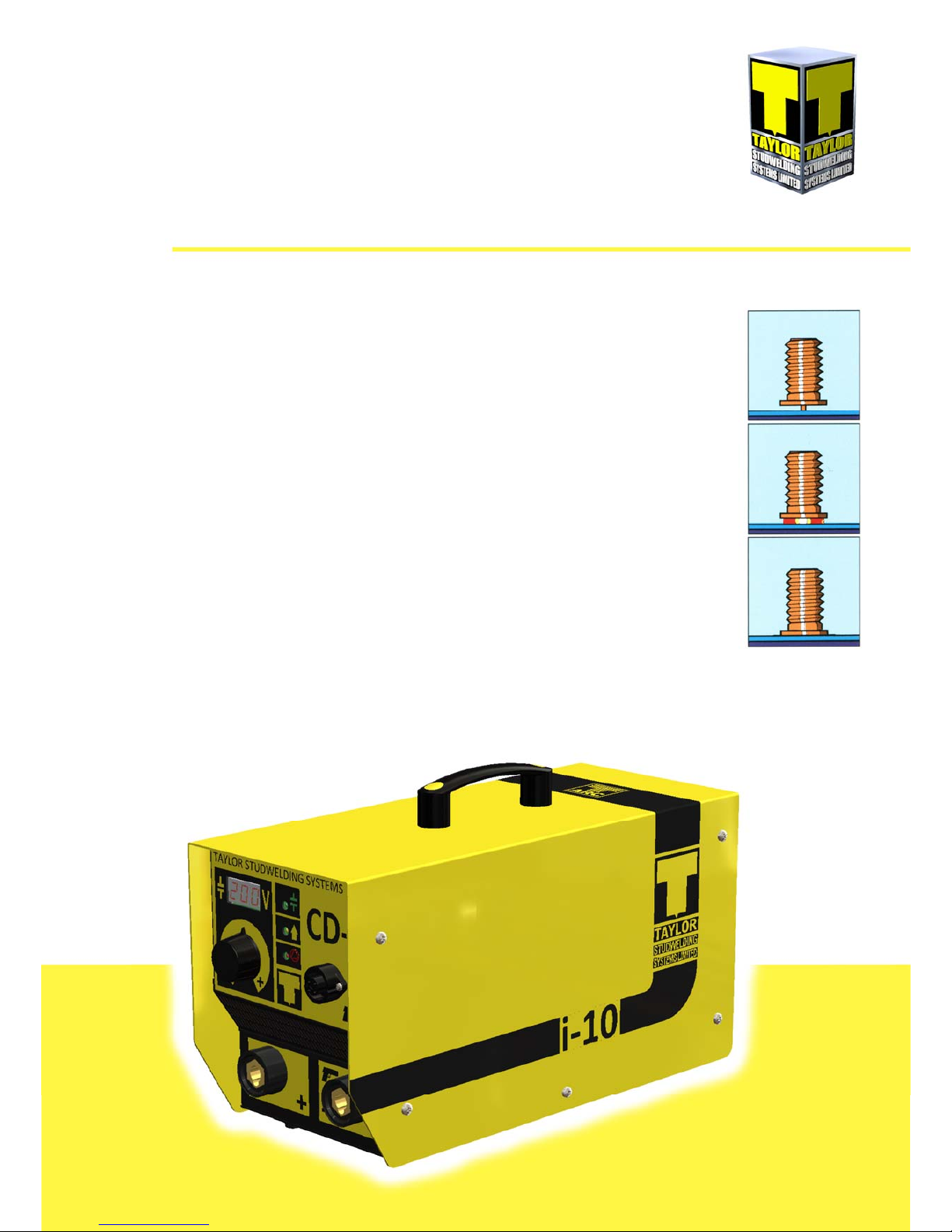
THEPROCESS
CapacitorDischargestudweldingisaformofweldinginwhichtheenergyrequired
fortheweldingprocessisderivedfromabankofchargedcapacitors.Thisstoredenergyis
dischargedacrossthegapbetweenthetwosurfacestobeweldedastheyarepropelled
towardseachother.Thearcproducedheatsthetwosurfaces,melngathinfilmofmetal
oneachsurfaceandthepropellingforceclosesthegapbetweenthetwofaces,thus
formingaweld.
Incontactweldingthestudtobeweldedisforcedbyspringpressureontotheplate.
Atthispointthearcgapbetweenthetwocomponentsismaintainedbyasmallpiponthe
weldingfaceofthestud.Oniniaonofthehighcurrentpulsefromthecapacitors,thispip
vaporisesandanarcisdrawnbetweentheworkpieceandthestud.Theheatfromthisarc
meltsthebaseofthestudandtheareaoftheworkpiecedirectlybeneaththestud,whilst
thespringpressurefromthepistolacceleratesthestudtowardstheworkpiece.Within3
to4millisecondsthestudhitstheworkpieceandthearcisexnguished.Thekinec
energycontainedinthemovingstudandtheremainingspringpressure,forgethemolten
partstogethertoformaweld.

V‐4J
GUIDETOEXTERNALFEATURES
8
FRONTPANEL
1. CARRYINGHANDLE
2. WELDINGVOLTAGEDISPLAY
3. WELDINGVOLTAGECONTROLKNOB
4. VENTILLATIONHOLES !DONOTOBSTRUCT!
5. WELDINGEARTHPANELCONNECTOR
6. GREENLED‐INDICATESREADYTOWELD
7. AMBERLED‐INDICATESUNITISCHARGING
8. REDLED‐INDICATESUNITISINRESETMODE.WAIT10SECONDSANDRE‐STARTTHE
CONTROLLERWITHTHEON/OFFSWITCH.IFTHERESETCONDITIONPERSISTSAFAULT
HASOCCURED
9. WELDINGPISTOLCONTROLCONNECTOR
10. WELDINGPISTOLPANELCONNECTOR
1
2
3
4
5
6
7
8
9
10

V‐4J
GUIDETOEXTERNALFEATURES
9
BACKPANEL
1.RATING/SERIALPLATE 4.MAINFUSE
2.ON/OFFSWITCH 5.MAINSINLET‐IECSOCKETOR
3.VENTILLATIONFAN/GRILLE‐!DONOTOBSTRUCT! FIXEDCABLE(SEEINSET)
OPTIONSAVAILABLE
IMPORTANTNOTES!
DuetothepowerrequirementsandElectromagnecemissionsproducedduringnormaluse,this
machinemustonlybeoperatedinanindustrialenvironment.
TheunithasinvertertechnologyandisdesignedtooperatefromanysinglephaseACvoltagebetween
100and250VACat50Hz.
Neverobstructthefrontandrearpanelvenlaonholesortheundersideoftheunitasthismaycause
theunittooverheatduringoperaon.
Neverremoveanyporonoftheunithousingwithoutfirstisolangtheunitfromthemainselectrical
supply.
1
2
3
4
5
V‐4J
SETTINGUPANDWELDING
10
Setupthecontrolunitattheplaceofwork,
ensuringthatthemainsswitchisintheOFF
posion.Ensurethatthisisdoneinlinewiththe
notesandsafetyrecommendaonsonpages5and
6ofthismanual.
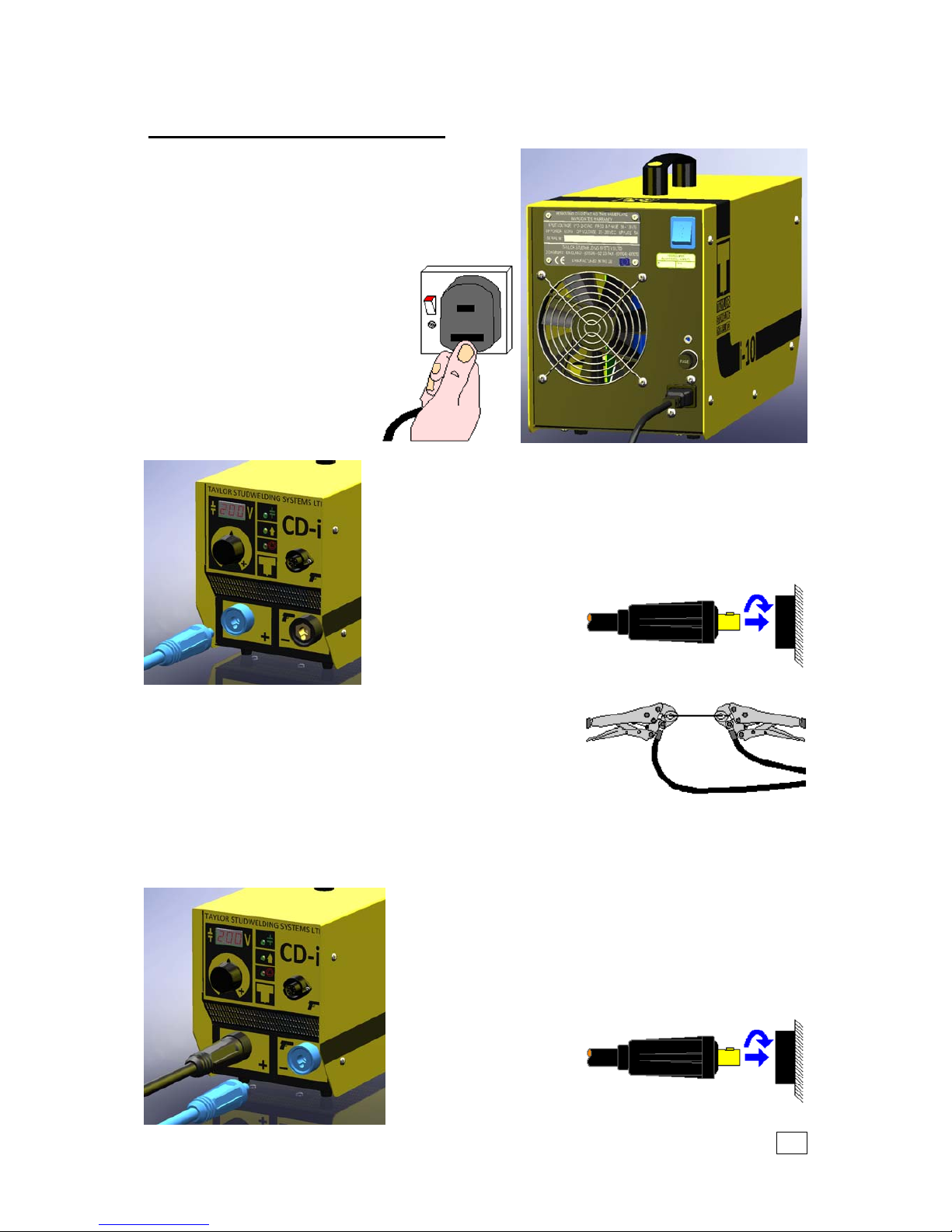
Plugthecontrollerintothe
correctmainsACsupply.The
controllerisratedforanysingle
phaseACvoltagebetween100
and250VACat50Hz.Ensure
thecorrectplugisfiedfor
yoursupplyinlinewithlocal/
naonalcodes.
Connecttheweldingearthcabletothecontrollerpanel
mountedplug.
Notethatthecableendplughasapegwhichmateswitha
keyslotinthepanelmountedsocket.
IMPORTANT!
Securetheconnectorwitha
clockwiseturnunlitlocks.
Failuretodothiswillresultin
damagetotheconnector
duringwelding.
Aachtheweldingearthclampstotheworkpieceat
approximately180°toeachother.Thiswillhelptoprevent
"Arcblow"whenweldingtakesplace.Priortofingthe
clamps,ensurethatthecontactareaoftheworkpieceis
freefromrust,paint,greaseetc.Asthiswillresultinapoor
weldingconneconandpoorresults.Wherepossible,route
theearthcablesawayfromtheoperatortopreventtheoperatorbeingposionedbetween
therunofthecableswhilstoperangtheequipment.
Connecttheweldingpistolcabletothecontrollerpanel
mountedsocket.
Notethatthecableendplughasapegwhichmateswith
akeyslotinthepanelmountedsocket.
IMPORTANT!
Securetheconnectorwith
aclockwiseturnunlit
locks.Failuretodothis
willresultindamageto
theconnectorduring
Other manuals for CD-i
1
Table of contents
Other Taylor Welding System manuals


Popular Welding System manuals by other brands


TAFA
TAFA 30*8B35 owner's manual

Lincoln Electric
Lincoln Electric INVERTEC V350-PRO CE Technical specifications

ESAB
ESAB Buddy Arc 145 instruction manual

CIGWELD
CIGWELD 636804 use instructions

Red-D-Arc
Red-D-Arc DC-400 Operator's manual

Hobart Welding Products
Hobart Welding Products Spool Gun DP 3035-10 owner's manual


