TB-Electronics Frequency Synthesizer F-SCAN2 User manual
Seite 1 von 45
The Frequency Synthesizer F-SCAN2
SW Version FS2 V1.10
INSTRUCTION MANUAL
This symbol identifies the equipment as type B
ATTENTION: Consult accompanying documents
WARNING: User’s with PACE MAKERS or PACE MAKER ELECTRODES should consult a
cardiologist prior to use of this device. The device could perhaps interfere
with – or even damage – the PACE MAKER.
NOTE: The device, all accessories, connectors and cables must be visually inspected for damage
frequently. A complete functional test must be performed and documented by a
professional once a year.
NOTE: The universal power supply shipped with the device is the only safe one to be used. Any
other power source could damage the F-SCAN2or become a hazard for the user.
NOTE: The device generates frequencies. The use of cables, adapters or accessories other than
the ones supplied or recommended by the manufacturer could cause malfunctions in
other appliances.
NOTE: The device’s integrated functions allow biological tests and applications described by the
author Dr. H.R.CLARK. They are also suitable for applications commonly named after
R.R.RIFE. The device is used under the sole responsibility of it’s operator
WITHOUT LIABILITY TO THE MANUFACTURER.

Seite 2 von 45
Preface
One of our prime objectives as a Swiss company is the development and manufacturing of
precise and reliable products for physical therapy based on years of experience. Some of
our products are well known and utilized internationally. As a small company we can afford
to keep in touch with our customers who often contribute to new developments.
May your work with the F-SCAN2be beneficial for you and for your clients.
Introduction
The FREQUENCY SYNTHESIZER F-SCAN2has been optimized for stationary as well as
‘out of office’ use by medical professionals and healing practitioners. The device advances
and expands the range of applications originally defined by its predecessor, the F-SCAN.
The units touch screen display can be tilted within 90 degrees. Itresponds quickly to
commands and is easy to operate.
The device generates precise SINE wave signals (DC-OFFSET) and SQUARE wave
signals (FULL WAVE or DC-OFFSET) and feeds them to a single OUTPUT connector.
A separate POWER PORT provides amplified signals synchronized with the signals
available on the OUTPUT port for use with light or magnetic coil adapters, etc.
The AMPLITUDE of the sine wave signals is preset. The amplitude of the square wave
signals can be individually adjusted in a broad range.
A TIMER can be assigned individually to each frequency or as a global function.
The special application modes “WOBBLE” and “PULSE” are global functions. If enabled,
they affect all frequencies used in an application.
A “Sweep To Next” mode allows a sweep between two adjacent values in a sequence of
frequencies.
The unique DIRP (Dual Integration Resonance Procedure) can be used to SCAN FOR
RESONANT FREQUENCIES in the unit’s frequency band between 1Hz and
15,000,000Hz. The sensitivity of the analysis function can be adjusted from the default
value of “L”=Low to “M”=Medium or “H”=High.
A WIDE BAND SWEEP can be performed.
A ZAPPER session is preprogrammed and can be started with a touch on the ZAPPER
icon.
All functions are controlled by a microprocessor. The built-in permanent (non volatile)
memory contains a list of the 235 pathogens identified by Dr. Hulda R. CLARK (called
CLARK table in this document) with their typical frequencies as well as a list of 348 low
frequency applications (called RIFE table in this document).
Seite 3 von 45
Table of contents
●WARNING and NOTES Page1
Introduction 2
Table of contents 3
Product highlights 4
●Elements for operation 5
Signals generated 6
Memory capabilities 7
●WHICH FUNCTION TO USE ? 7
General comments 8
●How to start the F-SCAN2? 8
●The Touch Screen
window 1 and 2 9
window 15
window 17
●Adjustment of amplitude 18
●INPUT AND USE OF FREQUENCIES 19
●USE OF THE INTERNAL FREQUENCY TABLES 21
●WIDE BAND SWEEP 23
●ZAPPPER 24
●DIRP 25
●Special features explained 28
●OPTIONS 29
Shippinglist 30
●Technical data 31
●Periodical maintenance 33
Accessories and spare parts 35
RIFE table, sequences of frequencies
CLARK table, list of pathogens and their frequencies

Seite 4 von 45
Product highlights
•The F-SCAN2is operated by a backlit monochrome LCD touch screen display of 320 x 240
pixels. Its viewing angle can be adjusted to the users comfort within 90 degrees. Touch
commands are executed instantaneously which reduces setup times.
•A single OUTPUT port on the right side of the device can be programmed and provides sine-,
square- and square 5Volt- signals.
•Square wave signals can be delivered FULL WAVE or DC-OFFSET – selectable with a switch.
Their amplitude can be adjusted with a potentiometer between 0Vpp and 27Vpp or 13.5Vpp.
•A POWER PORT on the rear side of the device provides amplified square wave signals
synchronized with those available on the OUTPUT port for use with light or magnetic coil
adapters, etc. The output range is from 0.1Hz to 1MHz with a preset amplitude of 14Vpp.
•Two frequency tables are permanently stored and items can be selected with a touch on an
alpha sorted name table and transferred to the operating memory.
•Frequency values between 0.1Hz and 3,000,000Hz can be set for square wave signals and
between 0.1Hz and 15,000,000Hz for sine wave signals.
•Integrated adjustable common and multiple individual TIMER.
•‘SWEEP’ – mode, for wide band application of frequencies.
•‘Sweep To Next’ – mode,allows to sweep between any two values of a frequency sequence.
•User accessible memory provides a capacity to store 50 data blocks permanently (until an
overwrite). Each data block can be comprised of up to 50 frequencies (with one decimal, if
required), their assigned signal form and the ‘Sweep To Next’ – choices (if applicable) and a
complete data set of a DIRP run (max. 1,000 analysis steps).
•Some user settings remain after power off until the user changes them again.
•DIRP (a special SCAN – procedure) to detect resonances within the frequency range of the
device.
•The results of a DIRP – analysis are displayed as a graph on the touch screen display (up to
1,000 increments).
•‘WOBBLE’- mode. If enabled, the signal will swing around the target frequency in a band
selectable in 27 steps between ±10Hz and ±9,000Hz . This is a global feature.
•‘PULSE’- mode. 4 pulse rates are selectable. This is a global feature.
•The content of the operating memory can be transferred via the RS232 communication interface
to an F-SCAN or to an F-SCAN2SATELLITE.
•‘F-SCAN’ software is available as an option. It allows to remote control the F-SCAN2from a PC
or Notebook via the RS232 communication interface. A serial printer can be attached instead of
a PC. The content of the operating memory, the DIRP data set, the DIRP graph, or the content
of ‘SETUP window 1’, can be printed to keep as a record.

Seite 5 von 45
Elements for operation
POWER PORT output of amplified signal to
drive accessories like magnetic coil
adapter, UV-light adapter, etc.
Socket for
POWER cable
connection.
RS232 connector for data
cable to a serial printer, a PC
or an F-SCAN2 SATELLITE
Multi signal OUTPUT. Signals
with all wave forms generated
by the device are delivered to
this port.
Switch to toggle from FULL WAVE
to DC-OFFSET for square signals –
except 5Vpp signal which is
permanent DC-OFFSET.
Potentiometer to adjust amplitudes of
FULL WAVE square signals between 0Vpp
and 27Vpp and the DC-OFFSET ones
between 0Vpp and 13.5Vpp.
Connector for
finger electrode.
(DIRP)
ON – OFF
switch
Backlit monochrome touch
screen LCD – operated by a
display pen.
The LCD assembly can be
tilted into a position of the
users choice within 90
degrees.
Display pen
Right side view
(display omitted)
LED confirms
signal output when
lit.
Rear view
(display omitted)

Seite 6 von 45
Signals available on OUTPUT connector
Signal available on POWER PORT
Vpp
SINE wave signal
10 V
Amplitude adjusted with
potentiometer
SQUARE FULL WAVE signal
Switch in to
p
p
osition
Amplitude adjusted with
potentiometer
SQUARE DC-OFFSET signal
S
wit
c
h in
bo
tt
o
m
pos
iti
o
n
Amplitude of square wave signals in relation to position of potentiometer is linear!
CAUTION: When using square wave signals, the output voltage (amplitude) must
be carefully adjusted to the user’s sensitivity. See chapter
Adjustment of amplitude
SQUARE DC-OFFSET signal
Amplitude preset to 5Vpp
SQUARE DC-OFFSET signal
Amplitude preset to 14Vpp
CAUTION: Polarity of POWER PORT is
opposite of “OUTPUT” !!!
Any connection between the two output ports
causes a short which damages the device
and/or the power supply !!!!

Seite 7 von 45
Memory capabilities built into the F-SCAN2
The library functions containing the CLARK table of frequencies of pathogens and the
RIFE table of sequences of frequencies - addressing disease symptoms – are fixed in
permanent memory and cannot be altered by the user.
User controlled settings of the TIMERs, the upper (“F MAX”) and lower (“F MIN”)
frequency limit’s and of the “Delta F” remain - even when the unit is turned OFF - until the
user changes them to other values.
The operating memory, which is used by all functions, remains active as long as the
device is powered up. This is called a volatile, or non-permanent, memory. It’s content is
lost when the power is switched OFF.
It’s content can be erased too from the SETUP window 1 with “STORE” followed by ‘E’.
The operating memory is organized as follows:
It has fifty positions labeled ‘01’ to ‘50’. Any value is entered into position ‘01’ unless the
icon “MEMO” is touched after the confirming ‘E’. The memory position counter changes to
‘02’ and is ready for the next entry.
It is important to observe the content of the operating memory if different functions are
performed in succession without separating them by ‘power OFF’. Values stored in the
operating memory with the INPUT OF A FREQUENCY, TRANSFER, RECALL or after
selecting a CLARK application, are automatically appended.
Playback from the operating memory always starts from memory position ‘01’.
Which function to use ? Let us assume that................
….a well founded diagnostic method names one or several pathogens as the cause for a
disease. A check of the attached list of pathogens identified by Dr. CLARK reveals that all
are covered in the list.
See chapter USE OF THE INTERNAL FREQUENCY TABLES to proceed.
….there is reason to believe that resonances not yet identified by other diagnostic
methods take part in causing disease symptoms. An attempt should be made to find them
with a DIRP analysis and to treat. See chapter DIRP to proceed.
….there are symptoms of a health disorder which can be precisely named. A check of the
attached list of RIFE disease symptoms reveals that the disorder is named.
See chapter USE OF THE INTERNAL FREQUENCY TABLES to proceed.
….the name of the health disorder is NOT in the attached list of RIFE disease
symptoms. Other sources however offer a SEQUENCE OF FREQUENCIES to treat the
disorder which shall be used.
See chapter INPUT AND USE OF FREQUENCIES to proceed.
….an attempt to do a DIRP analysis did not yield trustworthy results. It is conceivable that
a ‘wide band SWEEP’ prior to another DIRP may improve the situation.
See chapter WIDE BAND SWEEP to proceed.
….the ZAPPER function shall be used. See chapter ZAPPER to proceed.

Seite 8 von 45
General comments
The unit confirms activities acoustically. This fact will not be mentioned in the detailed
description of the functions. Sound and display light can be switched ON and OFF.
The power supply warms up slightly during operation.
Connect the gold plated handheld electrodes – or other application parts - with the BNC-
connectors of the application cable. Place the electrode on the red lead (anode) in the
user’s left hand and the one on the blue lead (cathode) in his right hand, or apply other
electrodes where you see fit (NEVER on an open wound!).
NOTE: The term SQUARE WAVE is used in this document instead of
RECTANGULAR WAVE which is more commonly used in Europe.
How to start the F-SCAN2
The unit is ready for use as soon as the power supply is connected to an outlet, the
plug attached to the socket POWER and the ON OFF switch on the rear panel set
to ON.
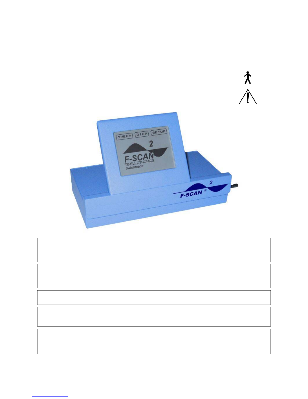
This ‘Start-up’ window is displayed
after power ON. It shows the unit’s
name, the company and country of
origin and the release level of the
internal software.
The window offers the 3 tabs
THERA, DIRP and SETUP to touch
in order to prepare the device for an
application.

Seite 9 von 45
The TOUCH SCREEN, SETUP window 1
The touch screen display is used to enter settings and commands for all functions of the F-
SCAN2. Its sensitive surface reacts to a soft touch with the plastic pen delivered with the
device or to a touch with the tip of a finger. The latter is less accurate, can cause wrong
entries and may leave undesired fingerprints. The touch screen can be cleaned with a soft
cloth – perhaps moistened with a mild glass cleaner.
IMPORTANT: NEVER TOUCH THE SCREEN SURFACE WITH A POINTED
INSTRUMENT OF ANY MATERIAL.
NEVER USE A SOLVENT TO CLEAN THE DISPLAY.
SETUP window 1 was designed to enter standard values and settings which will be
explained in the chapters named in the boxes pointing to them.
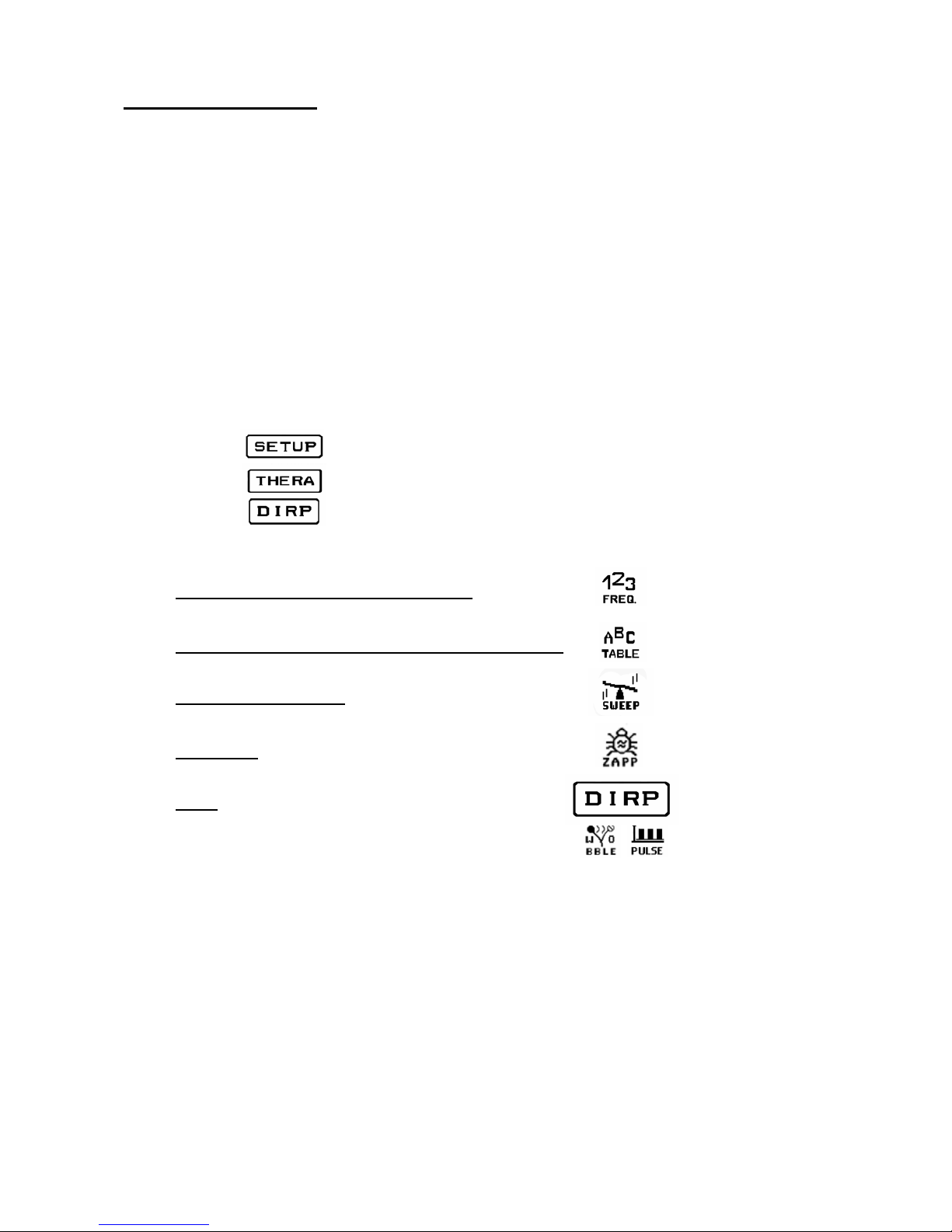
Touch to display the
numerical block to enter a
number between ‘01’ –
‘50’ to recall a data block
(Frequencies and/or a
DIRP data set
previously stored).
Touch to display the numerical block to
enter a value for the common”TIMER”
for frequencies. The same window
allows you to assign individual time
elements to each frequency of a set.
This will be explained on the next page.
Touch to display the numerical
block to enter a number between
‘01’ – ‘50’ to store a data block.
(Frequencies and/or a DIRP data
set). Touch ‘E’ on the numerical
block in position ‘00’ to erase all
values from the operating memory.
Touch to toggle the
beep which confirms
each input or
completed operation
ON or OFF.
Touch to select one
of 27 WOBBLE
ranges between
±10Hz and
±9,000Hz
Touch to display
window 2 of the
tab SETUP.
Touch to display the
numerical block to
enter a value for the
separate timer for
the broad band
“SWEEP”.
Touch to display the
numerical block to
enter a value for
“F MAX”, which is
the upper frequency
limit for a DIRP or a
broad band
SWEEP.
Touch to display the
numerical block to enter a
value for”F MIN” which is
the lower frequency limit
for a DIRP or a broad
band SWEEP.
Touch to display the
numerical block to enter a
value for “DELTA F”
which is the size of each
step taken during a DIRP
or a broad band SWEEP.
Touch to toggle the
touch screen
panel’s backlight
ON or OFF.
Touch to select one
of 4 PULSE rates;
5, 10, 15 or 20
pulses per second.

Seite 10 von 45
The button in window 1 of the tab has been touched to display
window 2.
The icon in window 1 of the tab has been touched.
Touch to print either
the content of the
operating memory,
or all data of a DIRP
run, or the DIRP
graph on a serial
printer attached to
the RS232 socket of
the device.
Touch to print
settings of SETUP
window 1 on a serial
printer attached to
the RS232 socket of
the device.
Touch to switch
language of name
tables from German
to English and vice
versa.
Touch to transfer the
content of the ope-
rating memory to an
F-SCAN via the RS232
interface.
Touch to transfer the
content of the ope-
rating memory to an
F-SCAN2SATELLITE
via the RS232 interface.
This time field
shows the present
setting and changes
to the new minute
and/or second value
entered after confir-
mation with ‘E’.
Touch the left or right arrow to move between memory
positions ‘01’ to ‘50’. A time element entered in position ‘01’
is valid for all frequencies of a set. If individual time
elements are needed, they can be assigned to the memory
positions corresponding to the frequencies held. The “50
TIMER”-feature must be ON to activate individual TIMERs for
an application.
The icon’s black
background signals
that it has been
selected. The time
field to it’s right
shows the present
setting and changes
to the new one after
the seconds are
confirmed with ‘E’.
Touch to toggle the
“50 TIMER “-feature
ON and OFF.

Seite 11 von 45
The icon – TIMER has been touched.
The icon has been touched.
This field shows the
present time for a
SWEEP in minutes
and seconds. It’s
background changes
from active to inactive
as soon as new
numbers have been
entered and
confirmed with ‘E’.
This field shows the
present time for a
SWEEP in minutes
and seconds. It
changes to new
values as soon as a
new entry for
seconds has been
confirmed with ‘E’.
The numerical block
disappears and the
icon’s background
changes from active
to inactive.
Enter a new value for minutes first and touch ‘E’ to jump to
seconds, change and confirm with ‘E’. Touch ‘E’ without an
input if you want to keep the present setting of either the
minutes or the seconds.
This field shows the
present setting in Hz
for the upper
frequency limit
“F MAX” for a broad
band SWEEP or for a
DIRP. It changes as
soon as a new value
has been entered
with the numerical
keys and is confirmed
with ‘E’. The
numerical block
disappears and the
background of field
and icon changes
from active to
inactive.
Enter a new frequency value and confirm with ‘E’. In case of
an input error touch zero until all 8 digit’s on the left are filled
with zero. Then input the correct value. The value must be
higher than “F MIN”.
Seite 12 von 45
The icon has been touched.
The icon has been touched.
This field shows the
present setting in Hz
for the lower
frequency limit
“F MIN” for a broad
band SWEEP or for a
DIRP. It changes as
soon as a new value
has been entered
with the numerical
keys and is confirmed
with ‘E’. (NEVER set
to ZERO!)The
numerical block
disappears and the
background of field
and icon changes
from active to
inactive
Enter a new frequency value and confirm with ‘E’. In case of
an input error touch zero until all 8 digit’s on the left are filled
with zero. Then input the correct value. The value must be
lower than “F MAX”.
This field shows the
present setting in Hz
for the “DELTA F” for
a broad band
SWEEP or for a
DIRP. It changes as
soon as a new value
has been entered
with the numerical
keys and is confirmed
with ‘E’. The
numerical block
disappears and the
background of field
and icon changes
from active to
inactive.
Enter a new frequency value and confirm with ‘E’. In case of
an input error touch zero until all 8 digit’s on the left are filled
with zero. Then input the correct value. The value must be
within the range between “F MAX” and “F MIN”.
Seite 13 von 45
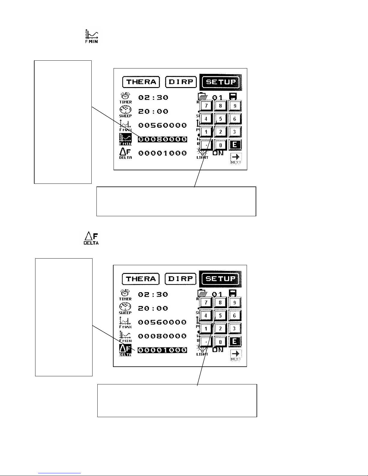
The icon has been touched.
The icon has been touched.
This field shows the
present position ‘00’
of the permanent
memory.
If a number between ‘01’ and ‘50’ is entered and confirmed with ‘E’, a set of
frequencies - or a DIRP data set with the frequencies selected for therapy -
previously stored, will be recalled to the operating memory.
Note that a DIRP overwrites the values for “F MIN”, “F MAX” and “DELTA F”
temporarily.
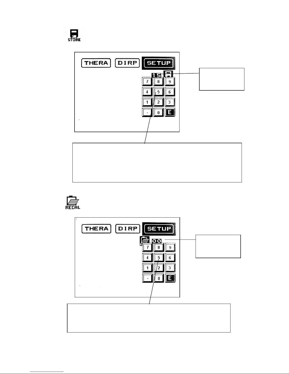
This field shows the
present position ‘00’
of the permanent
memory.
If a number between ‘01’ and ‘50’ is entered and confirmed with ‘E’, a set of
frequencies, or a DIRP data set with the frequencies selected for therapy, will
be transferred from the operating memory to permanent memory.
Touch ‘E’ in position ‘00’ to erase all values from the operating memory.
Touch ‘E’ in position ‘99’ to restore all default settings into the device.
Touch ‘E’ in position ‘98’ to erase all entries from the 50 positions of the permanent
memory (this may take up to 10 minutes!).
Seite 14 von 45
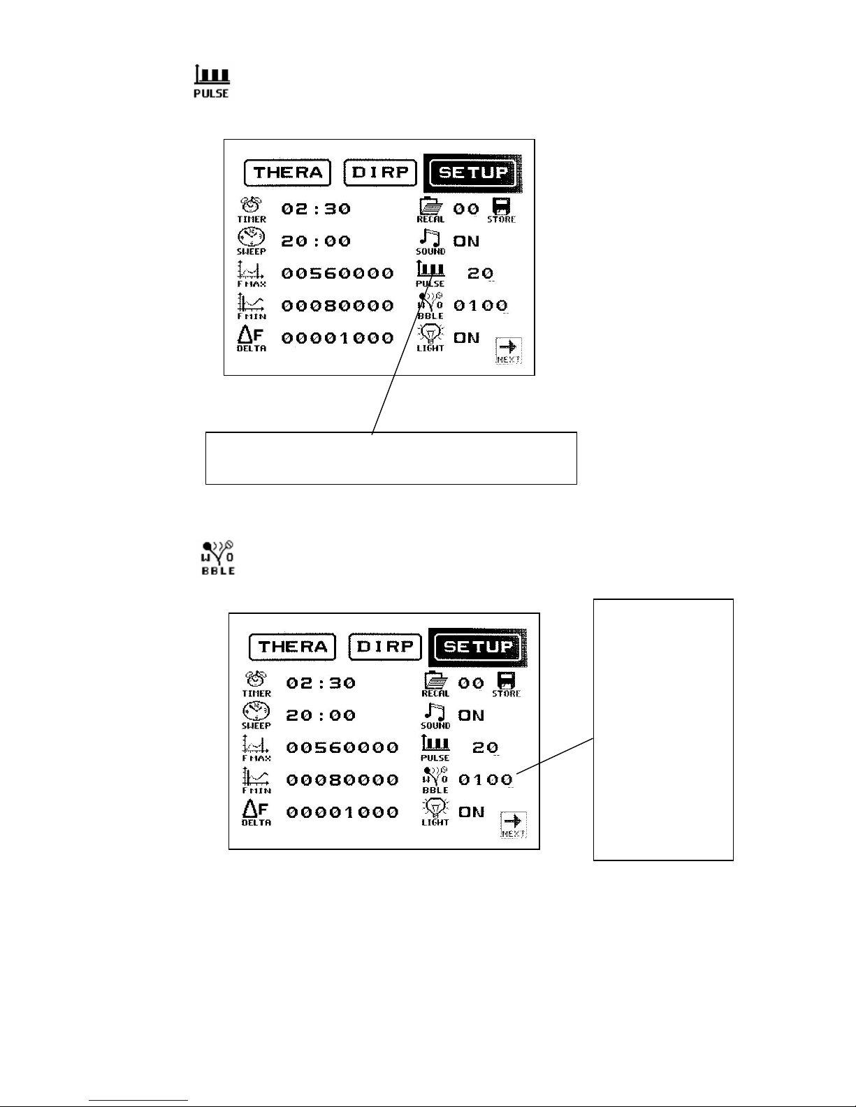
The icon has been touched.
The icon has been touched.
The icon „PULSE“ offers 5 positions, the pulse rates 5, 10, 15
or 20 (per second) and OFF. Pulsing resets to OFF whenever
the device shuts down.
The icon „WOBBLE“
offers 27ranges and
the OFF position.
( ± 10 to 90Hz, 100 to
900Hz, 1,000 to
9,000Hz.) The
selected range
remains active until the
feature is set to OFF
with a continuous
touch on the icon. The
same procedure must
be followed to change
from a higher to a
lower range or to
change a wrong entry.

Seite 15 von 45
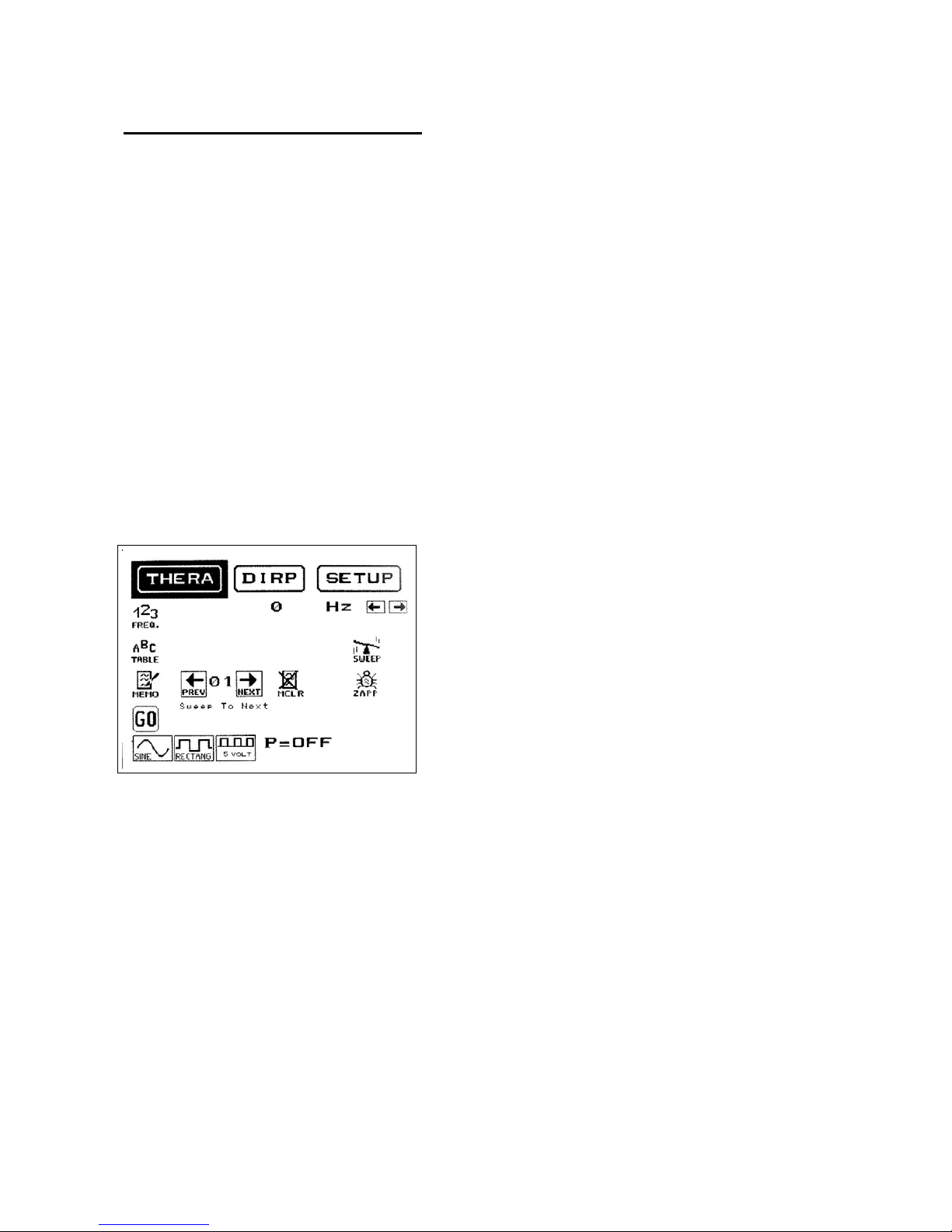
The tab (for THERAPY) has been touched to display it’s window.
The Frequency value
entered last, or active in
any function, is
displayed in this field.
Touch to display the
numerical block to enter
a Frequency value in the
operating range of the
device between 0.1Hz
and 15,000,000.9Hz.
Touch to decrease
the actual frequency
value in increments
of “DELTA F” set in
the window SETUP.
Touch to start the
broad band SWEEP.
A separate window is
displayed which will
be shown later.
For information only.
The “PULSE” feature
is OFF. If it had been
set in the window
SETUP the pulse rate
would be shown here.
Touch to display a
separate window
with alpha sorted
name lists to
select from the
internal tables.
Touch to enter the
active frequency
into a free position
of the operating
memor
y
.
Touch to start a
ZAPPER session. A
separate window is
displayed which will
be shown later.
Touch to increase
the actual frequency
value in increments
of “DELTA F” set in
the window SETUP.
Touch to send the
active frequency
to the output ports
(the PowerPort has
a limited range).
The background of
the icon changes to
black and it’s label
from GO to STOP.
Touch to clear the
memory position
shown between the
arrow icon’s.
Touch to switch to a
higher memory
position which will
be shown between
the arrow icon’s.
Touch to switch
to a lower
memory position
which will be
shown between
the arrow icon’s.
Touch to activate the special
feature “Sweep To Next”. It can
be used between any two
adjacent frequencies stored in
the operating memory. It has to
be activated in the position of the
lower of the two frequencies. The
time assigned to this frequency
determines the duration of the
Sweep.

Seite 16 von 45
Wave form selection
The icon’s for wave form selection have a toggle function. Press once to activate, press
again to deactivate, and so on. Selection of a wave form is mandatory after entering a
random frequency or when using the memory function.
Example: The frequency 1,000Hz shall be sent to the output as a square signal:
1& 0& 0& 0& E
To deactivate the output press again.
The user can switch between wave forms any time.
Touch to select a square wave output signal, completely DC-OFFSET, with a fixed
amplitude of 5Vpp.
The internal software activates this signal form at the start of a ZAPPER session.
Touch to select a ‘FULL WAVE’ square output signal. The amplitude can be adjusted with
the potentiometer between 0 and 27 Vpp. If the switch next to the potentiometer is set to it’s
bottom position, the output signal changes to DC-OFFSET. The amplitude can then be adjusted
with the potentiometer between 0 and 13.5 Vpp.
ALWAYS TEST A USER’S SENSITIVITY PRIOR TO AN APPLICATION OF SQUARE WAVE
SIGNALS (not required for a ZAPPER session).
See chapter Adjustment of amplitude
Touch to select a sine wave output signal, completely DC-OFFSET, with a fixed amplitude
of 10Vpp.
The internal software activates this signal form at the start of an application if no other signal
form has been selected by the user.
Seite 17 von 45
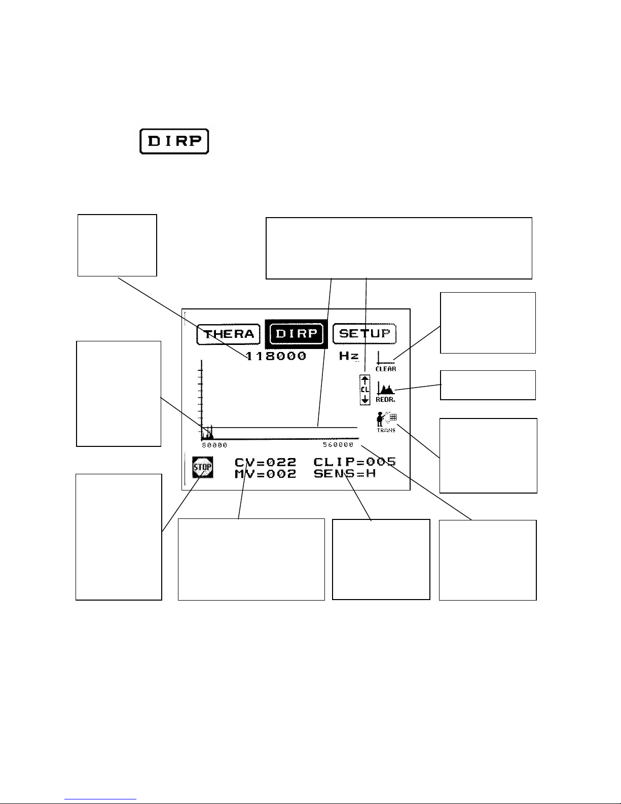
The tab has been touched to display it’s window.
The frequency
value sent from
the device during
a DIRP is
displayed here.
The horizontal line can be moved vertically within the graph
field with the up and down arrows CL (Clipping Level). All
values of the graph touching or passing this line can be
transferred for further use to the operating memory with a
touch on the icon “TRANS”.
Touch GO to start
the D I R P.
The background of
the icon changes
to black and it’s
label from GO to
STOP.
(This picture shows
a DIRP in
progress.)
Touch to CLEAR
the graph field
without deleting the
data from the
operating memory
The resonance
feedback (MV) to
the frequency
value issued by
the device is
stored in the
operating memory
and displayed on
the graph.
The Conductivity Value (CV) in %
is displayed here. The distance of
the horizontal line from the x-axis
(CLIP=005) is shown on the right
and the Measured Value (MV)
underneath the CV.
“F MIN” and “F MAX”
set in window 1 of the
tab SETUP are
shown under the
horizontal axis of the
graph.
Touch to
TRANSFER resonant
values selected with
the horizontal line
(CL) to the operating
memory.
Touch to REDRAW
the graph.
The sensitivity of the
analysis function can
be adjusted from the
default value of
“L”=Low to
“M”=Medium or
“H”=Hi
g
h
Seite 18 von 45
ADJUSTMENT OF AMPLITUDE
Low frequencies with high amplitudes can cause discomfort, skin irritations or even burns,
especially if inadequate electrodes or worn self adhesive pads are used.
F-SCAN2can generate square wave signals with amplitudes of up to 27Vpp with the
potentiometer fully open.
WE STRONGLY RECOMMEND THAT THE AMPLITUDE BE SET CAREFULLY PRIOR
TO A THERAPY WITH LOW FREQUENCIES.
This can be done as follows:
Turn the knob of the potentiometer counter clockwise to ‘0’.
Attach an application cable to the ‘OUTPUT” connector and to the electrodes to be used.
Connect the power supply to an outlet, attach the plug to the socket POWER and set the
switch in the back panel to ON.
The ‘Start-up’ window is displayed. Touch the tab THERA.
REMOVE THE ELECTRODES UNTIL READY FOR TREATMENT. MAKE SURE NOT TO
CHANGE THE SETTING OF THE POTENTIOMETER FOR THIS USER.
Touch “1 2 3“ to display the numerical block.
Input 100(Hz) and confirm with ‘E’.
Select the square wave signal.
HAND THE ELECTRODES TO THE USER.
TURN THE DIAL OF THE POTENTIOMETER SLOWLY
CLOCKWISE (UP) UNTIL THE USER REPORTS
‘FEELING THE CURRENT FLOW’ - OR ‘A SLIGHT
VIBRATION IN HIS HANDS’ - WHICH HE CAN EASILY
TOLERATE.

Seite 19 von 45
INPUT AND USE OF FREQUENCIES and selection of variables.
The icon “1 2 3” has been touched.
The arrows above the numerical block can be used to raise or lower the frequency value
displayed in increments of “DELTA F” set in window 1 of the tab SETUP.
If you want to use one frequency only, first touch the desired signal form (example
SQUARE WAVE) and then the icon “GO”.
The signal is delivered on both output ports for the time (example 02 : 30) set in window 1
of the tab SETUP. The display shows:
Continued on next page!
The frequency field shows ‘0’,
the numerical block awaits an
input of a frequency value within
the operational range of the
device between 0.1Hz and
15,000,000Hz.
Each digit entered appears in the
frequency field for review. In
case of an error enter zero in all
8 digit’s and start anew. Confirm
the correct value (for example
7,500Hz) with ‘E’.
7,500Hz in the frequency field.
Position ‘01’ of the operating memory.
A “STOP”-icon. A touch stops delivery.
A “SKIP”-icon. A touch stops delivery and
skips to.the next frequency stored (not shown
here).
The TIMER counting down from the original
02 : 30, now at 02 : 24. The total time for an
application of 3 frequency values (TT).
The signal form selected (black background)
and the PULSE – feature = OFF.
If the icon “PAUSE” is touched, it flashes,
delivery stops and the icon’s “SKIP” and
“STOP” disappear. The TIMER, now at 02 :
20, stops too.
Delivery continues if “PAUSE” is touched
again. The icon’s “STOP” and “SKIP”
reappear.
When the TIMER ends the display changes
back to the window of the tab “THERA”. The
icon “1 2 3” is touched again.
Seite 20 von 45
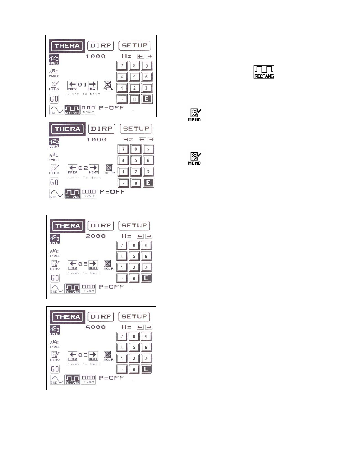
If a sequence of frequencies with square wave form
should be entered (for example 1,000, 2,000 and
5,000Hz), the MEMO function can be used to input
the whole sequence.
-select the wave form by touching
-select “123” for numerical input
-input <1>, <0>, <0>, <0>, <E>
-press to store 1,000Hz. This frequency now
occupies memory position ‘01’. The memory counter
opens position ‘02’.
-input <2>, <0>, <0>, <0>, <E>
-press to store 2,000Hz. This frequency now
occupies memory position ‘02’. The memory counter
opens position ‘03’.
-input <5>, <0>, <0>, <0>, <E>. This frequency is
stored in memory position ‘03’ without touching
MEMO, since it is the last value and no further
memory position needs to be prepared.
It is possible to check the input of the frequencies
with the icon’s “PREV” and “NEXT”.
If you want to sweep in the range between value 2
and 3 (in our example 2000 to 5000) go to memory
position ‘02’ and touch the line “Sweep To Next”. The
device calculates the steps for the sweep and
performs it for the time assigned to memory position
‘02’.
If you want to sweep longer than the time assigned
to an individual frequency:
Touch the tab SETUP.
Touch the icon “TIMER”.
Touch ‘50’ to switch the “50 TIMER”-function ON.
Touch the icon “PREV” until the memory position
counter shows ‘02’.
Enter the new time and confirm with ‘E’.
Touch the tab THERA.
Touch the icon “GO” to play back the content of all
memory positions with a frequency value greater
than 0.
Table of contents


