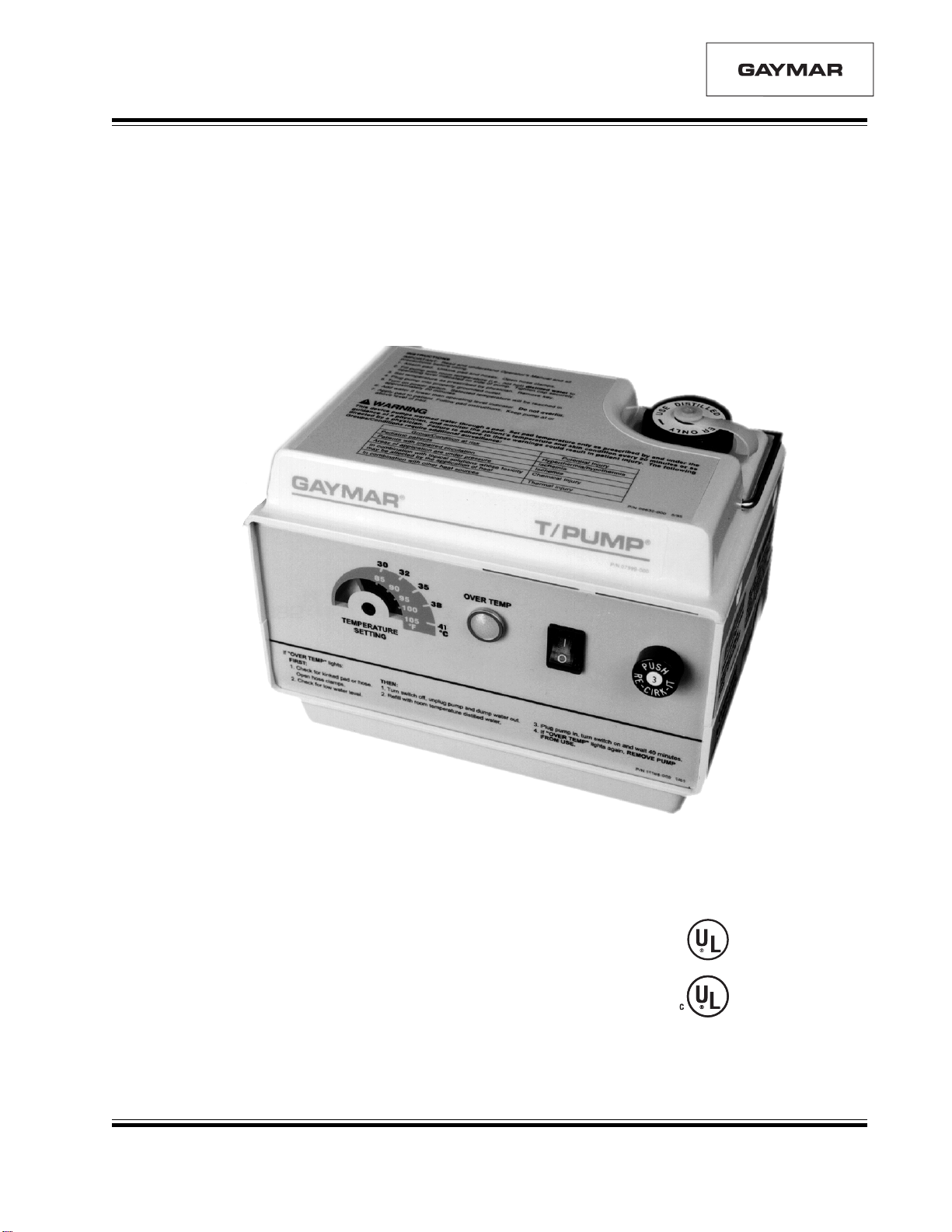
Gaymar T/PUMP TP400 Series User manual

®
P/N 11203-000 5/01
T/PUMP®
TP400 Series
Heat Therapy System
SERVICE MANUAL
LISTED 304L
STANDARD (NORME)
C22.2 NO. 125 RISK
CLASS (CATEGORIE
DE RISQUES) NO. 2G

REFERENCE PRINT
SERVICE MANUAL
T/PUMP (TP400 Series)
BEFORE YOU BEGIN . . .
T/PUMP, T/PAD, Mul••T••Pad, Clik-Tite, and Gaymar are registered trademarks of Gaymar Industries, Inc.
U. S. PATENT 4,068,870 © 2001. Gaymar Industries, Inc. All rights reserved. www.gaymar.com
READ AND UNDERSTAND THIS T/PUMP SERVICE
MANUAL AND ALL PRECAUTIONS (SEE PAGE 2) PRIOR
TO SERVICING THE T/PUMP.
The purpose of this manual is to provide operation, service, and repair
information for GAYMAR heat therapy pumps.
Check the shipping carton for damage immediately upon receipt. If package
damage is discovered, the device should be unpacked with the carrier's
agent present. Any claims for shortage or damage must be filed with the
delivering carrier by the purchaser. Do not return pumps damaged in
shipment to GAYMAR without contacting our Technical Service
Department for advice (see phone numbers below). If damaged goods are
returned to GAYMAR without notifying the carrier, GAYMAR will assume
the repairs will be made at the customer's expense.
RECEIVING INSPECTION
Merchandise returned to GAYMAR must be accompanied by a Return
Goods Number (RG#), issued by GAYMAR, authorizing goods to be
returned. Call Customer Service or Technical Service at
(716) 662-2551
1 800 828-7341
Advise model, serial number, and nature of problem. You will be given a
Return Goods Number (RG#).
The serial number can be found on the back of the T/Pump (see figure 2,
page 4).
TO RETURN PUMPS
TO FACTORY FOR
REPAIR OR EXCHANGE

REFERENCE PRINT
SERVICE MANUAL
T/PUMP (TP400 Series)
1
CONTENTS
ILLUSTRATIONS
SAFETY PRECAUTIONS .......................................................... 2
INTRODUCTION....................................................................... 3
FEATURES .................................................................................. 4
SPECIFICATIONS ...................................................................... 5
OPERATING INSTRUCTIONS ................................................ 6
STORAGE AND CLEANING .................................................... 7
THEORY OF OPERATION ....................................................... 8
FUNCTIONAL CHECK AND SAFETY INSPECTION ....... 10
INSPECTION FORM ................................................................ 15
DISASSEMBLY / REASSEMBLY ............................................. 16
CALIBRATION ......................................................................... 19
TROUBLESHOOTING ............................................................ 21
REPLACEMENT PARTS LISTS .............................................. 28
WARRANTIES .......................................................................... 31
1 T/PUMP®HEAT THERAPY SYSTEM ...................................... 3
2 T/PUMP FEATURES/SPECIFICATIONS ................................ 4
3 CLIK-TITE®CONNECTORS..................................................... 6
4 T/PUMP COMPONENTS .......................................................... 9
5 MOTOR...................................................................................... 11
6 TPC1 TEST COVERS ............................................................... 22
7 FUNCTIONAL CHECK TEST DIAGRAM ............................ 23
8 CIRCUIT DIAGRAM FOR T/PUMP ....................................... 24
9 CIRCUIT DIAGRAM FOR TPC1 TEST COVERS ................ 25
10 EXPLODED VIEW OF T/PUMP ............................................. 26
11 PC BOARD ASSEMBLY........................................................... 27
CONTENTS

REFERENCE PRINT
SERVICE MANUAL
T/PUMP (TP400 Series)
• Risk of explosion. Do not use in the presence of flammable
anesthetics.
• Risk of electric shock. Disconnect power before servicing
the T/Pump.
DANGER
SAFETY PRECAUTIONS
2
•Do not perform any powered tests with the reservoir empty.
Damage to the T/Pump may result.
CAUTION
•This device pumps warmed water through a pad. Set pad
temperature only as prescribed by and under the guidance of a
physician, and monitor the patient's temperature and skin
condition every 20 minutes or as directed by a physician. Fail-
ure to adhere to these warnings could result in patient
injury.
The following Groups/Conditions require additional surveillance:
WARNING
•Only qualified medical service personnel should repair the
T/Pump. Improper repair may result in death or serious
injury, equipment damage, or malfunction.
•Always perform the FUNCTIONAL CHECK AND SAFETY
INSPECTION (pp. 10-14) after making repairs and before returning
the T/Pump to patient use. Document your findings on the
INSPECTION FORM (p. 15). Improper repair may result in
death or serious injury, equipment damage, or
malfunction.
Group/Condition at risk Potential injury
Pediatric patients Hyperthermia/
hypothermia
Patients with impaired circulation Ischemia
Areas of application are under pressure Ischemia
In combination with topical solutions whose toxicity
may be affected by the application of heat Chemical
injury
In combination with other heat sources Thermal injury

REFERENCE PRINT
SERVICE MANUAL
T/PUMP (TP400 Series) INTRODUCTION
3
Figure 1 - T/Pump Heat Therapy System
Heat therapy is effective in the dilation of blood vessels, thereby increas-
ing the blood flow to the heated area. Heat therapy has a variety of uses,
the most common being treatment of aches and pains in joints and
muscles.
The GAYMAR T/Pump®Heat Therapy System provides a means of
applying heat therapy by supplying temperature controlled water through
a connector hose to a Gaymar T/Pad®. The hose is terminated in
easy-to-use Clik-Tite®connectors.
The T/Pad provides the interface for delivering the heat therapy. The
unique button design allows water to flow and provides trouble-free
operation when the pad is folded. This reduces the number of pads your
facility must keep in inventory. The pads are applied to the part
of the body requiring heat therapy, and the circulating water maintains
the pad at the set point temperature. The temperature setpoint is
key-operated to prevent tampering.
The T/Pads can be interconnected to provide therapy to more than one
body site at a time.
Single Pad Multiple Pads

REFERENCE PRINT
SERVICE MANUAL
T/PUMP (TP400 Series)
Attached Hose 10 ft (305 cm) dual channel. Connectors have male/female
with Clik-Tite fittings (see fig. 3, p. 6) allowing pads to be interconnected,
Connectors providing therapy to more than one body site at a time
(fig. 1, p. 3).
Tip-over Turns heater off if pump is tipped.
Switch NOTE: This does not activate the OVER TEMP light.
Hospital ID A label is provided on the back of the T/Pump for your
Label convenience. Use a felt tip or ball point pen to add any
required hospital identification.
OVER TEMP Indicates the pump and heater have been turned off.
Light This light is activated by the two OVER TEMP safety
thermostats. Refer to the TROUBLESHOOTING section.
Circuit Breaker When the circuit breaker trips, the small button in
the center will extend 1/4", exposing a white band.
Refer to the TROUBLESHOOTING section.
OVER TEMP Either of two limit thermostats will shut off pump and heater
Safety if the high temperature limit is exceeded. The OVER TEMP
Thermostats light will glow. Refer to the TROUBLESHOOTING section.
FEATURES
FEATURES
Figure 2 - T/Pump Features/Specifications
4

REFERENCE PRINT
SERVICE MANUAL
T/PUMP (TP400 Series) SPECIFICATIONS
Size (approx.) 8-1/8" x 5-5/8" x 6-1/4" (20.6 cm x 14.3 cm x 15.9 cm)
Weight (empty) 5 lbs, 2 oz (2.3 kg)
Reservoir capacity 51 oz (1500 ml) maximum
Flow rate 9 gph (34 lph) minimum with pad attached
Ambient operating 60°F to 90°F (15.6°C to 32.2°C)
temperatures
Storage temperatures –30°F to 160°F (–34.4°C to 71.1°C)
(empty)
Temperature setpoint 85°F to 105°F (29.4°C to 40.6°C)
range
Average operating ±2°F at 105°F setting
temperature accuracy
Power cord 18 AWG, 3 conductor, 9 ft (274 cm), Type SJT
with molded, hospital grade plug
Circuit breaker 3 amperes
1st backup limit Bimetallic (trip point fixed)
thermostat 108°F to 115°F (42.2°C to 46.1°C)
(manifold mounted)
2nd backup limit Bimetallic (trip point fixed)
thermostat 108°F to 122°F (42.2°C to 50°C)
(well mounted)
Current leakage 100 microamperes* maximum
* applies to all models except TP420,
which is 200 microamperes maximum
Ground resistance 0.5 ohm maximum
Electrical requirements TP400* TP401 TP420
Voltage (VAC) 120 100 220
Frequency (Hz) 60 50/60 50/60
Current (amps) 1.8 2.0 1.0
Power req'd (watts) 200 200 200
* Tested to UL 544 and
CSA C22.2, No. 125
SPECIFICATIONS
5

REFERENCE PRINT
SERVICE MANUAL
T/PUMP (TP400 Series)
6
OPERATING INSTRUCTIONS
START-UP PROCEDURE
CLIK-TITE®CONNECTORS:
To attach Clik-Tite connectors from hose to
pad:
1. Insert male fittings into female fittings
with a twisting motion (figs. 3A and 3B).
2. When fittings are fully inserted, snap
locking ring into place (figs. 3C and 3D).
3. To disconnect, simply reverse the
procedure.
4. To open or close the hose pinch clamps:
•Open the clamp by pushing the
serrated end (fig. 3E).
•Close the clamp by pressing the clamp
together (fig. 3F).
NOTE: Refer to figure 1 (p. 3) and
item 9 (p. 7) when connecting
multiple pads.
1. Before filling, always attach a T/Pad to the T/Pump connector hose.
Unkink pad and hose. Open hose clamps.
2. Open the fill cap on top of the pump. Fill the pump with room
temperature (i.e., not hot) distilled water to the operating level
indicated on the side of the pump. NOTE: Using tap water will
decrease the life of the pump.
3. Insert temperature setting key. Set temperature as prescribed by the
physician. Remove key to prevent tampering.
4. Plug T/Pump into a properly grounded outlet.
5. Turn on the power switch. The selected water temperature will be
reached in approximately 20 minutes.
6. If the water level drops below the operating level, add water.
Do not overfill. Overfilling can result in reduced pump motor
life.
7. Apply T/Pad to the patient. Follow T/Pad instructions.
8. For specified performance, keep the pump at or above the level of the
pad.
9. If the pump is placed below the pad(s), water will drain into the pump
when it is shut off. If the pump has been overfilled or if multiple pads
are connected, excess water can leak out onto the floor or cause
reduced motor life.
Figure 3E–3F—Hose Pinch Clamps
3E 3F
Figure 3A–3D—Clik-Tite®Connectors

REFERENCE PRINT
SERVICE MANUAL
T/PUMP (TP400 Series)
7
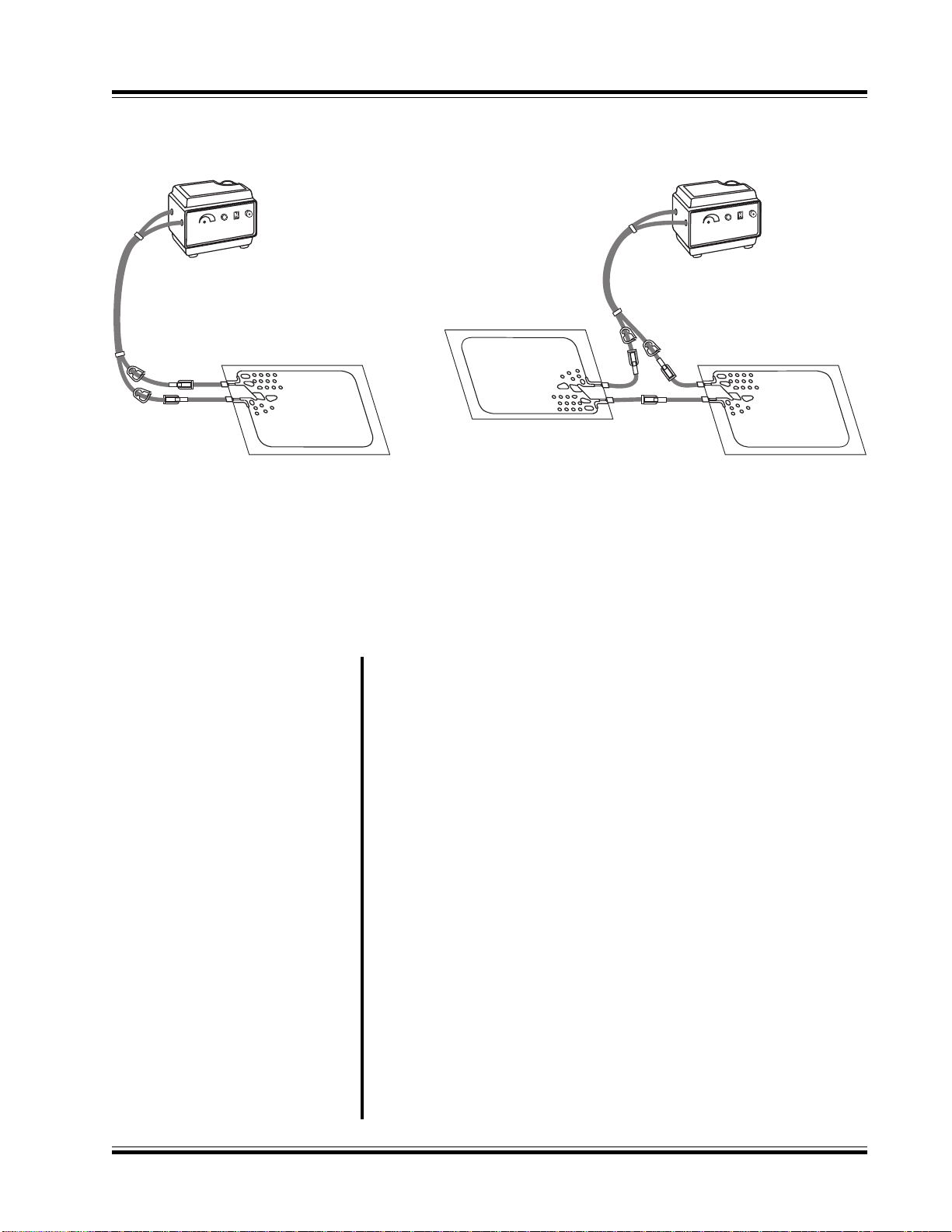
Disconnect pad. Connect ends of the connector hoses together. Open
hose clamps. Leave water in the reservoir. To prevent hose kinks, coil the
hose rather than folding it. Fasten the hose and cord with strap.
Disconnect pad. Connect ends of the connector hose together. Open hose
clamps. Add 1/4 ounce AirKem A-33, GAYMAR MTA33 germicidal or
equivalent to water already in reservoir. Run for two (2) minutes. Drain
pump. To prevent hose kinks, coil the hose rather than folding it. Fasten
the hose and cord with strap and store pump.
Unplug the power cord. Disconnect the pad or hoses from one another,
keeping hoses at or above the level of the T/Pump. Remove the fill cap and
invert the T/Pump over a sink. When all fluid has drained from the hoses
and reservoir, replace the fill cap and connect the hoses together.
Unplug the power cord.
To clean the external surfaces, use a non-abrasive cleaning solution (such
as warm, soapy water) and a damp cloth.
To clean the fluid system, drain the pump. Fill the reservoir to the operat-
ing level indicated on the side of the pump. Add 1/4 ounce GAYMAR
catalog MTA33 germicidal or equivalent. Set the temperature indicator to
its lowest setting (fully counterclockwise). Start the
T/Pump and circulate the solution for one hour. Drain the solution and
refill the pump with distilled water. Using distilled water retards algae
growth and mineral buildup.
Change the distilled water monthly or more often depending upon use.
For best results use only GAYMAR T/Pads®or Mul••T••Pads®. The unique
button design allows water to flow and provides trouble free operation
when the pad is folded. This reduces the number of different sizes of pads
your facility must keep in inventory. The T/Pads can be interconnected to
provide therapy to more than one body site at a time (see fig. 1, p. 3). For
a brochure listing the various T/Pads, contact the GAYMAR Customer
Service Department (see inside cover for telephone numbers).
An optional bed bracket (model TP20A) is available to mount the T/Pump
on the footboard of a bed.
Storage (Short term)
Storage (Long term)
Draining
Cleaning
Pads / Accessories
STORAGE/CLEANING
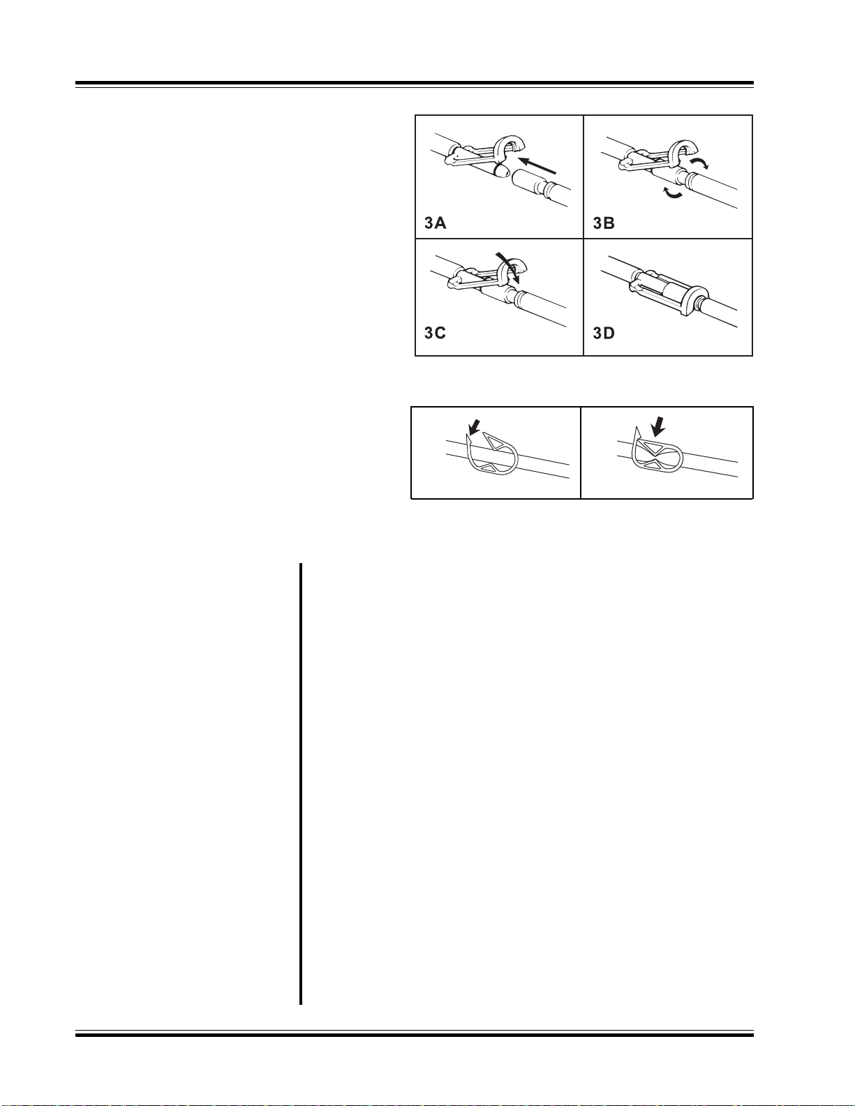
SHUTDOWN PROCEDURE 1. Turn off pump before disconnecting pad. Close hose clamps. To
prevent water spillage, always disconnect pad from pump with
connectors raised above the level of the pad and pump.
2. Connect the T/Pad Clik-Tite connectors together.
3. Connect the ends of the T/Pump connector hose together.
STORAGE AND CLEANING

REFERENCE PRINT
SERVICE MANUAL
T/PUMP (TP400 Series)
8
There are four devices that control the operation of the heater in the
GAYMAR T/Pump:
•The temperature controller is thermistor actuated (fig. 4, item 1, p. 9).
This controller is adjustable over a temperature range of 85°F to 105°F
(29.4°C to 40.6°C). The desired water temperature is set with a special
removable key (fig. 4, item 7). To prevent unauthorized temperature
setting changes, remove the key after the temperature has been set.
•The manifold backup limit thermostat (fig. 4, item 9) is mounted on the
brass manifold block (fig. 4, item 8). This thermostat senses water
temperature flowing to the pad and will shut off the pump and heater
and activate the OVER TEMP light if the water temperature exceeds
specific limits. The purpose of the manifold backup limit thermostat is to
prevent the pump from providing water at too high a temperature to
the pad.
•The well backup limit thermostat (fig. 4, item 5) is mounted on the brass
plate (fig. 4, item 11) that extends along and under the heater (fig. 4,
item 4) near the bottom of the reservoir. This thermostat senses water
temperature in the reservoir and will shut off the pump and heater and
activate the OVER TEMP light if the reservoir temperature exceeds
specific limits. The purpose of the well backup limit thermostat is to
both prevent the pump from providing water at too high a temperature
to the pad and to protect the pump from high temperature damage due
to a low water level.
•The tip-over switch (fig. 4, item 2; see also fig. 11, item 64, p. 27) is
mounted on the PC board. This mercury-type switch will shut off the
heater if the pump is tipped more than 45° from the vertical position.
NOTE: The tip-over switch does not shut off the pump
motor or activate the OVER TEMP light.
The pump (fig. 4, item 12) is a sump configuration driven by an impedance
protected, shaded pole AC motor (fig. 4, item 6).
The return hose fitting (fig. 4, item 10) is machined internally to act as an
orifice. This maintains a back pressure in the pad to make it resistant to
flow restrictions.
WATER TEMPERATURE
CONTROL
THEORY OF OPERATION
FLUID SYSTEM

REFERENCE PRINT
SERVICE MANUAL
T/PUMP (TP400 Series)
9
T/PUMP COMPONENTS
FIGURE 4 - T/PUMP COMPONENTS
BOTTOM
TOP
(wire harness removed for clarity)

REFERENCE PRINT
SERVICE MANUAL
T/PUMP (TP400 Series)
FUNCTIONAL CHECK &
SAFETY INSPECTION
10
FUNCTIONAL CHECK
This section is designed to provide a complete check of all pump param-
eters. The order of tests should be followed so that the functional testing
can be completed in the least possible time.
Follow the FUNCTIONAL CHECK AND SAFETY INSPECTION procedures
carefully, paying particular attention to test setups. Any deviation from the
setups, procedures, or test equipment may result in incorrect or mislead-
ing results.
Before making any repairs, be sure to recheck your test setup, procedure,
and test equipment.
Risk of electric shock. Disconnect power before servicing the
T/Pump.
•Only qualified medical service personnel should repair the
T/Pump. Improper repair may result in death or serious
injury, equipment damage, or malfunction.
•Always perform the FUNCTIONAL CHECK AND SAFETY INSPECTION
after making repairs and before returning the
T/Pump to patient use. Document your findings on the INSPECTION
FORM (p. 15). Improper repair may result in
death or serious injury, equipment damage, or malfunction.
Do not perform any powered tests with the reservoir empty.
Damage to the T/Pump may result.
To assure the optimum performance, dependability and safety, the
following should be performed once per year (or as specified in the
facility's preventive maintenance program) and after making repairs.
TPT9 ------------------------- GAYMAR Flow and Temperature Tester
TFC1 ------------------------- Thermometer, 30°F to 125°F (-2°C to 52°C),
1°C accuracy, 12" long, 3" immersion (e.g.,
Brooklyn Thermometer #73544 or equivalent,
Brooklyn Thermometer Co., Farmingdale, NY
11735)
T/Pad ------------------------- Any GAYMAR “12” or “22” series T/Pad
TPC1 ------------------------- GAYMAR T/Pump Test Cover
Ground Resistance Tester
Current Leakage Meter
Distilled Water------------- 2 liters (approximate)
Synthetic Oil ---------------- Anderol #465 (GAYMAR P/N 77137-000)
INSPECTION FORM -------- (p. 15)
DANGER
WARNING
CAUTION
INTERVAL
REQUIRED TOOLS

REFERENCE PRINT
SERVICE MANUAL
T/PUMP (TP400 Series)
11
FUNCTIONAL CHECK
1. Examine the line cord along its entire length for physical damage, such
as cuts or cracked insulation. A damaged line cord should be replaced
rather than repaired. Check the quality of the strain reliefs at both ends
of the line cord.
2. Examine the plug on the line cord to be sure it is in good condition. If
unit has non-molded type plug, open plug and check for wire breakage
and loose terminal screw(s). If defective, replace with a hospital grade
plug. Torque terminal screw(s) and outside housing screws to 12 in.-lbs.
3. Operate switches and control settings at all positions. Replace if
defective.
4. Visually inspect pump. Check for cracked or damaged plastic parts.
Be sure unit is unplugged. Remove retainer cap. Remove four (4)
screws holding cover and remove cover. (Be sure not to lose fill neck
gasket.) Perform visual inspection of all internal parts. Remove any
accumulated dirt with a vacuum cleaner or compressed air hose. Leave
cover off for balance of inspection.
5. Check Clik-Tite connectors for cracks or missing O rings. Replace
connectors if necessary.
1. Locate the motor manufacturer's ID on the top bearing housing.
If the pump motor is by Jakel, no oiling is required. If the pump motor is
by Uppco, proceed with the following oiling instructions.
2. Oil the pump motor every 6 months with Anderol #465 (GAYMAR
P/N 77137-000) or equivalent to extend the life of the T/Pump motor.
Anderol #465 is a synthetic oil. Do not use a petroleum-based oil since
it will leave a residue as it breaks down, causing the motor to seize.
Add four (4) drops of oil to the vent hole in the bearing housing of the
motor located below the fan. Using a micro oiler, apply a similar
amount to the lower bearing at the location indicated in figure 5.
PHYSICAL CONDITION
CHECK
MOTOR LUBRICATION
Figure 5 - PUMP MOTOR
NOTE: Early versions of
the pump motor have an
oiler tube which does
not effectively distribute
oil to the lower bearing.
Do not use the oiler
tube to apply oil to the
lower bearing. Use a
micro oiler to apply oil
directly to the locations
shown in figure 5.

REFERENCE PRINT
SERVICE MANUAL
T/PUMP (TP400 Series)
FUNCTIONAL CHECK
12
1. When connecting the test cover, do not remove any wiring
connections in the T/Pump. Simply clip the test cover alligator clips
onto terminals with the same color wire.
2. Connect TPC1 test cover (see fig. 6A/6B, p. 22 and 9A/9B, p. 25).
Always match the color of TPC1 wiring connections to the color of
T/Pump wiring. Be sure to keep wires away from fan. Install test cover.
Be sure to push cover on tightly. It is not necessary to install screws.
3. Connect pump with test cover, pad and TPT9 flow/temp tester (see
fig. 7, p. 23). Be sure the TPT9 is connected to the supply side of the
T/Pump, before the pad.
4. Fill unit with room temperature distilled water and replace fill cap.
Connect any “12" or “22" series T/Pad. Place pad on an insulating
material (e.g., cloth or towel).
5. Set both test cover switches to the OPEN position.
Risk of electric shock. Be sure unit is unplugged when performing
ground resistance test.
1. Use a ground resistance meter to measure the resistance between the
ground pin on the plug and the brass manifold block (fig. 10, item 47).
Contact is available through the hole where the hoses connect to the
pump. This value should not be more than 0.5 ohm.
It will be convenient to check current leakage at this point since the unit is
full and connected to a pad.
1. Measure the maximum current leakage in all combinations of heater
“ON” or “OFF” and power switch “ON” or “OFF.” Access to chassis
ground for current leakage testing is available through the hole where
the hose connects to the pump. The highest reading is typically less
than 30 microamperes (60 µA for the TP420). The maximum allowable
reading is 100 microamperes (200 µA for TP420). Record the highest
reading.
2. Disconnect leakage meter setup.
1. Check the tip-over switch at this point, since the test cover is on
and the unit is full. Set temperature to maximum (105°F) on dial.
The heater indicator (fig. 6, p. 22) will be on. Tip the unit approxi-
mately 45°. If the heater indicator goes out, the tip-over switch is
operating. If not, repair or replace the PC board (p. 17). Record
results.
DANGER
GROUND RESISTANCE
CHECK
CURRENT LEAKAGE
CHECK
TIP-OVER SWITCH CHECK
TPC1 TEST COVER
INSTALLATION

REFERENCE PRINT
SERVICE MANUAL
T/PUMP (TP400 Series) FUNCTIONAL CHECK
13
1. Be sure the pad is flat and warm (approximately 105°F) and at the same
level as the pump. Top of TPT9 float (see fig. 7, p. 23) should read at
least 9 gph. Record reading.
NOTE: If flow is below 9 gph, refer to TROUBLESHOOTING section
(p. 21).
1. Make sure temperature is set to maximum (105°F) on dial. Allow unit
to come to a steady temperature, approximately thirty (30) minutes.
2. To ensure accurate temperature readings, add a small amount of water
to TPT9 well. Insert thermometer in TPT9 well.
3. Take readings every thirty (30) seconds for five (5) minutes for a total
of ten (10) readings. The average of these readings should be 105°F
±2°F. Record the average value. If the unit is out of calibration, refer to
CALIBRATION section (p. 19).
4. Do not let the pump cool down. Proceed directly to Backup Limit
Thermostat Test.
1. With the pump operating properly at 105°F ±2°F, move the primary
shorting switch to the SHORT position (see fig. 6A/6B, p. 22). This will
short out the temperature controller and allow the pump to continue
heating to the trip point of the backup limit thermostat(s).
2. Carefully observe the rising temperature and record the highest
reading. When a thermostat opens, the pump will turn off, the OVER
TEMP light will be lit, and the HEATER INDICATOR light on the test
cover will turn off. (If the OVER TEMP light does not light and a
thermostat has tripped, replace the light.) Either the MANIFOLD or
WELL light on the test cover will be lit or both lights will be off,
depending on which thermostats have tripped.
•If the manifold thermostat light is on, then the manifold thermostat
has opened. The temperature recorded must be between 108°F to
115°F (42.2°C to 46.1°C). If the thermostat operates outside
its intended range, it must be replaced (see page 18).
Proceed to step 3.
•If the well thermostat light is on, then the well thermostat has
opened. The temperature recorded must be between 108°F to 122°F
(42.2°C to 50°C). If the thermostat operates outside its
intended range, it must be replaced (see page 18). Proceed to
step 3.
•If neither light is on, then both thermostats have opened at the same
temperature. To confirm this, toggle the thermostat shorting switch
to the MANIFOLD position. (The MANIFOLD light should be on.)
Next, toggle switch to the WELL position. (The WELL light should be
on.) If either thermostat opens outside its intended range as
defined above, it must be replaced
(see page 18). Proceed to step 4.
OPERATING
TEMPERATURE TEST
FLOW RATE TEST
BACKUP LIMIT
THERMOSTAT TEST

REFERENCE PRINT
SERVICE MANUAL
T/PUMP (TP400 Series)
14
FUNCTIONAL CHECK
LEAK TEST
COVER AND FILL NECK
GASKET REINSTALLATION
3. To test the remaining thermostat, toggle the limit thermostat shorting
switch to the position corresponding to the non-tripped thermostat.
(This will short out the previously opened thermostat and allow the
unit to continue heating.) Both thermostat indicator lights should be
off and the HEATER INDICATOR light should be on. Carefully observe
the rising temperature and record the highest reading. When the
water temperature rises to the trip point of the remaining
thermostat, the OVER TEMP light will be on, the pump will turn off,
the heater indicator light will turn off, and the appropriate thermostat
light will be on.
•If the manifold thermostat light is on, then the manifold thermostat
has opened. The temperature recorded must be between 108°F to
115°F (42.2°C to 46.1°C). If the thermostat operates outside
its intended range, it must be replaced (see page 18).
•If the well thermostat light is on, then the well thermostat has
opened. The temperature recorded must be between 108°F to
122°F (42.2°C to 50°C). If the thermostat operates outside
its intended range, it must be replaced (see page 18).
4. Unplug the unit, remove the test cover and proceed to LEAK TEST.
1. Immediately upon completion of Backup Limit Thermostat Test,
reinstall fill cap tightly. Put your finger over the hole in the cap and tilt
unit toward you so the front is down. Hold for three (3) minutes.
2. Return the unit to upright position and carefully check inside of tray
and reservoir tray joint for leaks. Repeat process turning pump on back
face. If leakage is found, refer to the DISASSEMBLY/REASSEMBLY section
(pp. 16-18), and correct problem.
When reinstalling cover, be sure the fill neck gasket (fig. 10, item 6, p. 26)
is in place. Push cover down as tightly as possible. Hold in place when
tightening cover screws.
This completes the FUNCTIONAL CHECK procedure. Return pump to
service if it is operating properly, or proceed to the DISASSEMBLY/
REASSEMBLY section pertaining to the problem(s).

REFERENCE PRINT
SERVICE MANUAL
T/PUMP (TP400 Series) INSPECTION FORM
15
qLmìãé=cìåÅíáçå~ä=`ÜÉÅâ=~åÇ=p~ÑÉíó=fåëéÉÅíáçå=cçêã
a~íÉ=||||||||||||||
jçÇÉä=kìãÄÉê=||||||||||||||||||||| pÉêá~ä=kìãÄÉê=||||||||||||||
fíÉã ~äìÉ
lh\ ^Åíáçå
kÉÉÇÉÇ\ ^Åíáçå=q~âÉå
EÅÜÉÅâ=çåÉF
NK
fåëéÉÅí=éÜóëáÅ~ä=ÅçåÇáíáçå=EäáåÉ=ÅçêÇI=éäìÖI=ÜçìëáåÖF
fåëéÉÅí=ÉäÉÅíêáÅ~ä=Åçãé~êíãÉåí
EëïáíÅÜÉëI=ÑìëÉLÅáêÅìáí=ÄêÉ~âÉêF
fåëéÉÅí=ÜçëÉ=ÅçååÉÅíáçåëI=`äáâJqáíÉ=ÅçååÉÅíçêë
OK iìÄêáÅ~íÉ=ãçíçê
PK `çååÉÅí=qm`N=íÉëí=ÅçîÉêX
ã~íÅÜ=ïáêÉ=Åçäçêë=çÑ=ÅçååÉÅíáçåë
QK jÉ~ëìêÉ=ÖêçìåÇ=êÉëáëí~åÅÉX=YMKR=çÜã=K=K=K
áåÇáÅ~íÉ=î~äìÉ
RK jÉ~ëìêÉ=ÅìêêÉåí=äÉ~â~ÖÉX=YNMM=”^G=K=K=K
áåÇáÅ~íÉ=î~äìÉ==EG==Ñçê=ãçÇÉä=qmQOMI=YOMM=”^F
SK `ÜÉÅâ=íáéJçîÉê=ëïáíÅÜ
TK jÉ~ëìêÉ=ÑäçïX=[=V=ÖéÜ=EPQ=äéÜF=K=K=K=áåÇáÅ~íÉ=î~äìÉ
UK jÉ~ëìêÉ=çéÉê~íáåÖ=íÉãéÉê~íìêÉ=]=NMRøc=œ=Oøc=K=K=K
áåÇáÅ~íÉ=~îÉê~ÖÉ
VK
oÉÅçêÇ=ã~åáÑçäÇ=Ä~Åâìé=äáãáí=íÜÉêãçëí~í=íêáé=éçáåíX
NMUøc=íç=NNRøc=EQOKOø`=íç=QSKNø`F=K=K=K=áåÇáÅ~íÉ=î~äìÉ
oÉÅçêÇ=ïÉää=Ä~Åâìé=äáãáí=íÜÉêãçëí~í=íêáé=éçáåíX
NMUøc=íç=NOOøc=EQOKOø`=íç=RMø`F=K=K=K=áåÇáÅ~íÉ=î~äìÉ
l bo=qbjm=äáÖÜí=çéÉê~íÉë
NMK `ÜÉÅâ=Ñçê=äÉ~â~ÖÉ
NNK oÉáåëí~ää=ÅçîÉê=~åÇ=íÜÉ=Ñáää=åÉÅâ=Ö~ëâÉí
páÖå~íìêÉ===|||||||||||||||||||||||||||||||||||||||||||||||||||||||||||||||||||
Inspection forms vary from hospital to hospital. The
following sample form is intended as a guide so that the
important parameters are recorded.

REFERENCE PRINT
SERVICE MANUAL
T/PUMP (TP400 Series)
16
DISASSEMBLY/REASSEMBLY
COVER 1. Unscrew fill cap/valve assembly (fig. 10, item 1, p. 26) and remove.
Unscrew plastic retainer.
2. Remove the four screws which retain the cover, two on each end of
the pump.
NOTE: When reinstalling the cover, do not forget to replace the fill
neck gasket (fig. 10, item 6).
1. Place a screwdriver under fan hub (fig. 10, item 7, p. 26) and twist to
remove fan.
NOTE: When replacing the fan, make sure the hub is flush with top of
motor shaft.
2. Remove green ground wire and orange and blue power wires.
NOTE: To prevent breaking the motor lugs, support them when
removing the slip-on lugs.
3. Remove the four retaining screws and washers on the top face of the
motor.
MOTOR
Risk of electric shock. Disconnect power before servicing the
T/Pump.
•Only qualified medical service personnel should repair the T/Pump.
Improper repair may result in death or serious injury,
equipment damage, or malfunction.
•Always perform the FUNCTIONAL CHECK AND SAFETY
INSPECTION (pp. 10-14) after making repairs and before returning
the T/Pump to patient use. Document your findings on the
INSPECTION FORM (p. 15). Improper repair may result in
death or serious injury, equipment damage, or
malfunction.
Do not perform any powered tests with the reservoir empty.
Damage to the T/Pump may result.
DANGER
NOTE:
All wires are terminated with slip-on connectors. When text says
“remove wire,” the slip-on connector is to be removed from the
mating lug on the specific item.
CAUTION
WARNING

REFERENCE PRINT
SERVICE MANUAL
T/PUMP (TP400 Series)
17
DISASSEMBLY/REASSEMBLY
4. It is necessary to remove the reservoir to remove the motor. Remove
the eight (8) screws located around the inside wall of the tray.
NOTE: It is not necessary to remove the front label (fig. 10, item 37).
The front label is attached only to the tray and will slip off the
reservoir.
5. Gently separate the reservoir from the tray. Do not damage the large
O ring that seals the tray and reservoir.
6. Turn the tray on its backside (front label up). Place a screwdriver
against the white impeller in the bottom of the pump housing to
prevent the impeller from turning and remove the screw retaining the
impeller. It is not necessary to remove the bottom housing (fig. 10, item
24) of the pump.
7. The impeller may now be slipped off the shaft. Return the tray assembly
to an upright position. The motor may be removed by lifting straight
up.
8. Center the new motor seal gasket over opening and insert new motor
through seal. Replace impeller onto shaft and secure motor.
9. Do not overtorque the four (4) motor mounting screws. Torque value
is 6 to 8 in.-lbs.
10.If tray inserts are loose or motor mounts are worn, a new tray with
sensor bracket should be installed.
1. Remove the ground wire (green) and the two (2) heater wires (red and
blue). NOTE: On reassembly, the red wire goes on to the front post
of the heater.
2. Remove the three (3) nuts retaining the heater. The screws are
retained in the tray. The heater can then be removed by raising and
tilting the top of the heater toward the left side of the T/Pump.
3. Reassembly is the reverse of the above.
4. Do not forget to install heater gasket (fig. 10, item 11, p. 26).
1. Using the plastic key (fig. 4, item 7, p. 9), turn the temperature indicator
to the eleven o'clock position. The slotted coupling should then be
positioned with the slot opening up.
2. Cut the plastic tie holding the wire bundle to the PC board. Remove
the red, orange, and blue wires from the PC board.
3. Remove the two screws (fig. 10, items 56 & 57, p. 26) retaining the PC
board. The board can then be raised from the tray, exposing the
thermistor probe assembly in the brass manifold block (fig. 10, item 47).
Use caution to be sure no strain is put on thermistor leads (fine white
wires).
4. Carefully remove the thermistor capsule from the manifold. To avoid
damaging the thermistor, do not pull on the wires. A dental pick or
scribe can be used to pry the capsule out of the hole.
HEATER
PC BOARD

REFERENCE PRINT
SERVICE MANUAL
T/PUMP (TP400 Series)
DISASSEMBLY/REASSEMBLY
5. On reassembly, put a small quantity of silicone heat sink compound
(Dow Corning #340 or equivalent) around the thermistor capsule.
Carefully insert the thermistor capsule into the hole on the brass
manifold block. To avoid damaging the thermistor, do not push on the
wires. The capsule may be seated by placing needle nose pliers or
tweezers on the edge of the capsule.
6. The remainder of the reassembly is the reverse of the above. Upon
inserting the P. C. Board, the potentiometer shaft (fig. 10, item 52,
p. 26) must be in the vertical position to mate with the slot in the
temperature indicator (fig. 10, item 40). Refer to CALIBRATION proce-
dures (pp. 19-20).
1. Remove the two (2) wire lugs. Note the position of the color coded
wires. Facing the front of the T/Pump, the purple wire goes on the left
hand lug, and the orange wire goes on the right hand lug.
2. Remove the two (2) screws retaining the thermostat to the brass
manifold block.
3. Reassembly is the reverse of the above.
4. Always be sure to check the backup limit thermostats according to the
FUNCTIONAL CHECK (pp. 13-14).
NOTE:
Do not attempt to replace the well thermostat. To insure
proper operation of this thermostat, it is riveted and sealed to the
tray assembly. Experience has proven that it cannot be successfully
replaced. If this item is defective, replace the entire tray
assembly (fig. 10, item 17, p. 26).
1. Remove the eight (8) screws (fig. 10, item 15, p. 26) around the inside
wall of the tray. Gently pry the reservoir from the tray.
2. Remove all components including seal, bushing, and clips from the old
tray and reinstall into the new tray assembly.
3. Attach the reservoir to the tray. Check that the reservoir ring seal (fig.
10, item 19) is properly located in the groove in the tray. Install the
eight (8) screws torqued to approximately 6 in.-lbs.
4. Always be sure to check the backup limit thermostats according to the
FUNCTIONAL CHECK (pp. 13-14).
18
MANIFOLD BACKUP
LIMIT THERMOSTAT
WELL BACKUP
LIMIT THERMOSTAT
TRAY
This manual suits for next models
2
Table of contents
Other Gaymar Medical Equipment manuals

Gaymar
Gaymar TP702 User manual

Gaymar
Gaymar T/PUMP TP472 User manual

Gaymar
Gaymar Thermacare TC3146 User manual

Gaymar
Gaymar Thermacare TC3249 User manual

Gaymar
Gaymar Sof Matt User manual

Gaymar
Gaymar MTA7900 User manual

Gaymar
Gaymar MEDI-THERM III User manual

Gaymar
Gaymar ATW8000 User manual

Gaymar
Gaymar MEDI-THERM II User manual

Gaymar
Gaymar medi-therm III MTA6900 series User manual