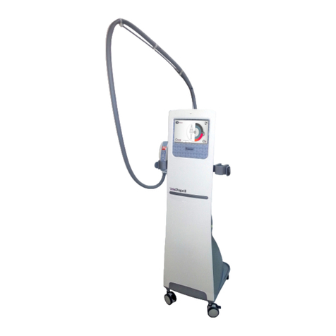
Atmos Variotherm plus User manual

Variotherm plus
GA1GB.140302.0 2022-02 Index 31
0124
Operating Instructions
Valid for devices delivered after July 2002.
English

2
Contents
1.0 Introduction.........................................................3
1.1 Notes on operating instructions ............................3
1.2 Intended use .........................................................4
1.3 Function ................................................................4
1.4 Explanation of symbols.........................................4
2.0 For your safety....................................................5
2.1 Important instructions for the maintenance of the
hygiene status of warm water irrigation units........6
3.0 Setting up and starting up .................................7
3.1 Scope of supply ....................................................7
3.2 Illustrations............................................................8
3.3 Connections........................................................11
3.3.1 Electrical connection...........................................11
3.3.2 Connecting a nystagmograph.............................11
3.3.3 Equipotential bonding conductor connection ......11
3.3.4 Water connection ................................................12
3.3.5 Connection of the irrigation handle .....................12
3.4 Starting up...........................................................12
4.0 Operation...........................................................13
4.1 Adjusting temperatures.......................................13
4.2 Selecting temperature levels...............................13
4.3 Adjusting stimulation time ...................................13
4.4 Adjustingowquantity ........................................13
4.5 Description of operating modes ..........................14
4.5.1 Thermal process for reducing bacterial count.....14
4.5.2 Irrigation mode....................................................14
4.5.3 Stimulation mode ................................................14
4.5.4 Energy saving mode ...........................................14
5.0 Cleaning and care.............................................15
5.1 General information on cleaning and disinfection15
5.2 Recommended disinfectants...............................15
5.3 Cleaning method for handle with jet connection
for water irrigation tip ..........................................16
6.0 Maintenance and service .................................17
6.1 Decalcication.....................................................17
6.2 Replacementoflter...........................................17
6.3 Sending in the device..........................................17
7.0 Troubleshooting................................................18
8.0 Accessories and spare parts...........................19
8.1 Accessories.........................................................19
8.2 Spare parts .........................................................19
9.0 Technical data ...................................................20
10.0 Disposal.............................................................22
11.0 Notes on EMC....................................................23
12.0 Notes..................................................................26

3
1.0 Introduction
1.1 Notes on operating instructions
These operating instructions contain important notes on how
tooperatetheVariothermplussafely,correctly,andeec-
tively. Therefore, they are intended not only for new oper-
ating personnel to be instructed in its use, but also for use
as a reference manual. They help to avoid risks and also to
reduce repair costs and down-times. Furthermore, reliabil-
ity and service life of the equipment will be increased. For
these reasons, these operating instructions must always
be kept available near the device.
Priortorstuse,pleaseperusethechapter“Foryoursafety”
in order to be prepared for any possible dangerous situa-
tions. To do this during work would be too late.
The basic principles are:
Judicious and careful work provides best protection
against accidents!
Operational safety and readiness for use of the device de-
pend not only on your capabilities, but also on the care and
maintenance given to the Variotherm plus. For this reason,
regular cleaning and service work are a must. Major main-
tenance and repair work may be carried out only by expert
personnel authorized by ATMOS. In case of repairs, you
should insist that only original spare parts are used. You will
then have the warranty that operational safety, readiness for
work, and the value of your device will be preserved.
• The product Variotherm plus bears CE marking CE 0124
according to EU Council Directive 93/42/EEC concerning
medical devices and meets the basic requirements of
Annex I to this directive.
• The product Variotherm plus complies with all applicable
requirements of Directive 2011/65/EU restricting the use
of certain hazardous substances in electrical and elec-
tronicequipment(“RoHS”).
• The declarations of conformity and our general standard
terms and conditions can be obtained on our website at
www.atmosmed.com.
• The quality management system applied at ATMOS has
beencertiedaccordingtointernationalstandard
EN 13485.
• Reprints—also in extracts—only with permission in writ-
ten form by ATMOS.
Abbreviations/symbols contained in these operating
instructions:
• Indicates a list
- Subdivision of a list/activity
The recommended sequence must be followed in each
case!
)Indicates particularly important advice!
ªDescribestheeectofanactivity
ATMOS
MedizinTechnikGmbH&Co.KG
Ludwig-Kegel-Str.16
79853 Lenzkirch
Germany
Telephone: + 49 7653 689-0
Fax:
+ 49 7653 689-190
+497653689-393(ServiceCenter)
E-mail: [email protected]
Internet: www.atmosmed.com

4
1.0 Introduction
1.2 Intended use
Product name: Variotherm plus
Main functions: Stimulation of the vestibular organ
Irrigation of the external auditory
canal
Intended purpose: Stimulation of the vestibular organ
Irrigation of the external auditory
canal
Intended users /
User prole:
Doctors and medical specialists
Intended patient
target group:
Patients of all ages without
restrictions
Medical conditions
to be diagnosed,
treated or moni-
tored:
Vertigo due to a disorder of the
vestibular organ
Hearinglossduetocerumeninthe
ear canal
Application organ: External auditory canal to eardrum
Application peri-
od:
Transient(<60min)
Application envi-
ronment:
Outpatient medical facilities, e.g.,
ENT practices, hospital outpatient
departments, medical care centers
Patient selection
criteria:
Patients with intact, physiological
eardrum and external auditory
canal
Indications: Dierentialdiagnosticsforvertigo
Hearinglossthroughimpacted
cerumen
Medical contra-
indications:
Pathological eardrum
Other contra-
indications:
Pathological external auditory canal
Warnings: N/A
The product is: active
Sterility/specic
microbial
status:
Non-sterile
Single use product
/ reprocessing:
Not a single-use product. Repro-
cessing according to instructions
for use.
1.3 Function
• Operating the main switch on the treatment unit automat-
ically activates the thermal process for reducing bacterial
count(seesection4.5.1).Then,automaticchangeto
energy saving mode.
• When removing the irrigation handle from its holder, au-
tomaticchangetotheirrigationmode.Here,theauditory
canal can be rinsed with water warmed up to 37 °C and a
owofatleast400ml/min.
• Possibility to switch to the stimulation mode for stimulat-
ingthevestibularorganwithareducedowofwater.
The Variotherm plus is equipped with a timer for
preselecting the stimulation duration.
1.4 Explanation of symbols
Follow operating instructions
According to ISO 7000/0434
DIN 30600/1008, IEC 348
Type B applied part
Fuse according to IEC 417/5016,
DIN 30600/0186
°C Temperature in degree centigrade
sTimer adjustment in seconds
Start
Stop
Timer
Cold stimulation level
Warm stimulation level
37 °C Irrigation level (water at a temperature value
of37°C)
•HeatingON
•HeatingOFF(energysavingmode)
Control output for connecting a nystagmo-
graph (graphical recorder as per DIN 30600,
IEC4175192)
Equipotential connection
DIN 30600 495, ISO 417 5021
Connection for waste water
Connection for water
Low Reducedow(forstimulationofthe
vestibularorgan)
High Highow(forrinsingtheauditorycanal)

5
2.0 For your safety
• The Variotherm plus is produced according to IEC 601 /
EN 60601 and listed in the following classes:
- VDE Class of protection 1
- ClassIIa(93/42/EEC).
• WARNING: In order to avoid the danger of an elec-
tric shock, this device should only be connected to an
earthed power supply.
• The device must be installed by a specialist authorized by
ATMOS(seesection3.3).
• The Variotherm plus may only be used under the supervi-
sionofskilledstawhohavebeenauthorizedbyATMOS
andtrainedinitsoperation(IEC601-1/EN60601-1).
• The mains voltage indicated on the type plate must corre-
spond to the values of the supply network.
• Make sure prior to every application of the equipment that
it is technically safe and in proper condition. Damaged
cables must be replaced immediately!
• Correctcongurationinassemblyofcountry-specic
connections:
- green/yellow:protectiveconductor(PE)
- blue:neutralconductor(N)
- blackorbrown:phase(L)
• Itisessentialthatthecountry-specicrequirementsfor
connection of medical equipment to the public drinking
water supply are considered. When in doubt, please
contact your local ATMOS partner.
• The control panel must be clearly visible and accessible
fortheuser.Ensuresucientstabilityoftheinstallation
surface.
• In order to safely disconnect the device from the mains
power supply, the power cable must be removed from the
IEC power connector of the Variotherm plus!
)In the thermal process for reducing bacterial count, hot
water is conducted through the irrigation handle. Please
do not take the handle from its holder or spray water!
)Metal parts can be hot!
)Prior to spraying, the water temperature must be checked
bytheuser(display)!
• Switchothemainswitchafternishingworkintheprac-
tice and close the water valve of the water supply.
• The Variotherm plus may be operated only in rooms used
for medical purposes, but not in areas subject to explo-
sion hazards and not in oxygen-rich environments.
• All additional equipment that is connected to the analog
and digital interfaces of the device must meet the require-
mentsofrelevantENspecications(e.g.,EN60950for
data processing equipment and EN 60601 for electrical
medicalequipment).Inaddition,congurationsmust
satisfysystemspecicationEN60601-1-1.Whenaddi-
tional equipment is connected to the signal input or signal
output section on the device, the person carrying out the
connectionisdeemed“asystemcongurationoperator”
and as such is responsible for meeting the requirements
ofsystemspecicationEN60601-1-1.Ifyouhaveany
questions, please contact your local specialist supplier or
ATMOS Technical Service.
• The irrigation jet must not get into contact with contami-
nated material.
• Only use the warm water jet when a hose tip is installed!
• Take caution to avoid injury to the eardrum when insert-
ing the water jet!
• For hygienic reasons, hose tips must be changed after
each patient. This also prevents retrograde contamination
of the warm water system.
• Use only for irrigation of the auditory canal!
• ATMOS is not liable for personal injury and damage to
property if
- no original ATMOS parts are being used,
- the advice for use in these operating instructions is
not being observed,
- assembly, new settings, alterations, extensions, and
repairs have been carried out by personnel not au-
thorized by ATMOS.
• Please note:
A medical isolation transformer with earth leakage
monitor or any similar safety system acc. to EN 60601-
1 is required if several devices are connected over one
common power supply. The transformer must correspond
to the power consumption of all the devices to be con-
nected.
• After switching on the device or at least once a week,
theowratemustbecheckedusingavolumemeasuring
funnel. The quantity of 500 ml/min may not be exceeded.
The water jet has to be straight.

6
2.0 For your safety
2.1 Important instructions for the maintenance of the hygiene status of warm water
irrigation units
Forlooseningcerumenintheauditorymeatusandforstimulatingthevestibularorgan,ATMOSoersthewarmwaterunits
Hygrothermplus(37°C)andVariothermplus(20°C‒47°C).
These units heat the drinking water that comes from the household connection to the preselected temperature. The operating in-
structionsmustbefollowed,orotherwisetheincreasednumberofpathogensintherinsewatercanaectthehealthofsensitive
patients.
Requirement for taking into use
ThewaterprovidedbythehouseholdconnectionmustatleastmeettheWHOguidelinesorthecountry-specicguidelines
for drinking water.
Connection
Freshwatermustowthroughthewallconnectionforaperiodofapprox.1minutepriortotheunitbeingconnected.*
Ensure that the installation is hygienically carried out! Disinfect the threaded connections with 70% alcohol before screwing
themintoplace.*
Weardisposablegloveswhencarryingoutmaintenanceworkonpartsthatcomeintocontactwiththewater.*
Carryoutthermalcleaningatleast3timesbeforeinitialoperation.*
*ThisworkiscarriedoutbytheATMOSservicetechnician.
Running operation
Before beginning everyday practice operations, switch on the unit and await the thermal cleaning process.
Afterthedevicehasbeenidleforalongperiodoftime(weekend,duringholidays,etc.),thethermalcleaningprocessmust
be initiated and repeated.
Werecommendthatthedevicebeswitchedoandonevery2hours,butnolaterthan4hours,tostartthethermalcleaning
mode.
Contactparts,e.g.,hosetips,mustbereplacedaftereverypatient(preventionofretrogradecontamination).
Before every use, spray water and check the temperature.
Service
Observehygienewhenchangingthesuspendedparticlelter(seecommissioning)(disposeoflterandcarefullycleanthe
lterglass).Ensurethatnocontactismadewithcontaminatedparts.
Carry out thermal cleaning after each service.
We recommend having regular germ count measurements of the water taken at the inlet and outlet of the unit. In the case of
acomplaint,datameasurementsmustprovewhetherthecontaminantsare“waterbacteria”or“skinbacteria.”

7
3.0 Setting up and starting up
3.1 Scope of supply
Quantity
1 Variotherm plus basic unit
1 Irrigation handle
1 Double-barrelled hose
3Jetconnectionshort,straight(80mm)
1 Splash guard
1 Rubber bushing for splash guard
2 Three-hole gasket
1Hosetipsforjetconnection(30pcs)
1 G3/4i-G1/4a-screwing (water tap G3/4 on
lterG1/4)
1 Cap nut G3/4
1Waterltercomplete
2Gasket(f.G1/4a)13x18x1
1G1/4a-G3/4a-reducer(lterG1/4on
waterhoseG3/4)
1 Water supply hose G3/4i, L = 3 m
1 Waste water hose G1/4i, L = 3 m
2Gasket(f.G1/4i)10x15x1
1 Cardboard box 455 x 340 x 250 mm
1 Padding for cardboard box
1 Operating Instructions

8
3.0 Setting up and starting up
3.2 Illustrations
Variotherm plus
3 0 3 7
—
11
3
[[
030 4
4
[
Fig. 1. Front view
1Main switch
2KeyswitchforheatingON/OFF(energysaving
mode)
3Coding switch for warm stimulation level
4Coding switch for cold stimulation level
5Coding switch for stimulation time
6Keyswitchforselectingtheirrigationlevel(37°C)
7Keyswitchforselectingthewarmstimulationlevel
(e.g.,44°C)
8Keyswitchforselectingthecoldstimulationlevel
(e.g.,30°C)
9Keyswitchforstart/stopofthestimulation
10Temperaturedisplay(two-gurenumber,increment
of1°C),actualvalueindication
11Displayofstimulationtime(two-gurenumber,incre-
mentof1s)

9
Fig. 3. Side view
1Holderforhandle
2Connection for double-barrelled hose
3Connectionforwastewaterhose*
4Connection for water supply hose
3.0 Setting up and starting up
F 14 AH
Fig. 2. Rear view
1Type plate
2Control output for controlling a nystagmograph
3Device socket with fuse compartment
4Equipotential bonding connection
p = +2000...+6000 hPa
t = +7...+19.5 °C
Press down ring
*

10
3.0 Setting up and starting up
Fig. 4. Irrigation handle
1Handle
2Connection for double-barrelled hose
3Three-hole gasket
4Adjusting screw
5Set screw
6Valve plunger
7Jet connection
8Splash guard
9Cap
10 Double-barrelled hose
The sprayer nozzle must be changed after each
patient.
!

11
3.0 Setting up and starting up
Fig. 5.
3.3 Connections
3.3.1 Electrical connection
• According to the directions of VDE 0107 and VDE 0100,
medically used rooms have to be equipped with a leak-
agecurrentprotectivecircuit(FIprotectivecircuit)with
a nominal leakage current of < 0.03 A. Installation must
correspond with VDE 0107.
• Connect the power cable to the socket on the unit (,
Fig.2).
• Insert the power plug in a correctly installed socket with
earthing contact.
3.3.2 Connecting a nystagmograph
• WhencontrollinganENG(electro-nystagmograph)ora
CNG(computer-nystagmograph)atoutput(,Fig.2),
please connect only recording equipment approved by
ATMOS. Connecting cable available from ATMOS (see
chapter8.0).
• At the end of the stimulation time, a trigger signal for a
nystagmograph is available at the rear 3-pole DIN socket.
This outlet is an electrically isolated photo transistor.
The emitter connection that has to be connected to the
ground line of the trigger inlet on the nystagmograph is
attached to pin 3. The open-collector connection is locat-
ed on pin 1 and is to be connected to the positive supply
voltage(+5Vor+12V)bymeansofapull-upresistance.
The maximum collector voltage of the transistor may not
exceed 80 MA.
3.3.3 Equipotential bonding conductor connec-
tion
• Connection for potential equalization (,Fig.2).Con-
nectingcableavailablefromATMOS(seechapter8.0).

12
3.3.4 Water connection
• Local requirements:
- Water tap with G3/4" external thread.
- Drinking water!
- Input water pressure: +2000...+6000 hPa.
- Feedtemperature:+7...+19.5°C(recommended),
but at least 0.5 °C below the required lowest cold
stimulation value.
- Drainagettings(REF502.0880.0)
• Connection to water supply and waste water:
- Therearecountry-specicregulationsfortheinstal-
lation to be considered when the unit is connected
to the public water supply. To comply with the rules
according to EN 1717, an unpressurized water sepa-
rationwithoverowisrequired.
Therefore, ATMOS recommends installing the water
separationunitATMOSAquaClean(REF502.1200.0)
between the water supply and the device in order to
meet the connection requirements according to EN
1717.
- Prior to connecting the unit to the water supply, the
feedlinemustbeushedcleanbyopeningthewater
tapforaminuteandallowingfreeowofthetap
water.
- Connectthelterunittothewatertapbymeansof
adaptor and gasket.
- Insert the gaskets in the cap nuts of the water supply
hose.
- Jointhenutswiththelterconnectionandtheunit
connection (,Fig.3).
- Insert the gaskets in the cap nuts of the waste water
hose.
- Join the nuts with the unit connection (,Fig.3)and
thedrainagettings.
- Thereisnospecialcalcicationsafetydeviceinte-
grated in the water system. Such a system is to be
connected when the respective drinking water is of
hardness grade 3 (14‒21°dHor2.5‒3.8 mmol/l =
hardwater)andofhardnessgrade4(from21°dHor
from3.8mmol/l=veryhardwater).
Please contact your local water supplier and/or
plumber.
Water
hardness
Millimole per
liter
°dH
1(soft) ≤1.3 ≤7.3 Calcication
protection system
is not required
2 (medi-
um)
1.3 to 2.5 7.3 to 14
3(hard) 2.5 to 3.8 14 to 21.3 Calcication
protection system
is required
4 (very
hard)
> 3.8 > 21.3
Close the water tap when the unit is not in use!
!
3.0 Setting up and starting up
3.3.5 Connection of the irrigation handle
• Insert a three-hole gasket (,Fig.4)inthedouble
barrelled hose (,Fig.4)andscrewitontheunitcon-
nection (,Fig.3).
)Use only three-hole gaskets or otherwise the unit will not
function correctly!
• Insert a three-hole gasket in the irrigation handle and
screw it on the free end of the double-barrelled hose.
• Open the water tap. Check whether all connections are
tight.
3.4 Starting up
• Insert the handle in its holder; the jet must point to re-
verse side of the unit.
• Switch on the unit (,Fig.1).
• Automaticdisplaytestwithdigitalnumbers“88”and
acoustic warning signal.
• Automatic activation of the thermal process will begin for
reducing bacterial count. Duration: 5 min.
• Automaticchangetotheirrigationmode(37°C).
• When the irrigation mode is not being used (handle is
notremovedfromitsholder),theunitchangestoenergy
saving mode after 5 min.

13
4.0 Operation
Before switching on the unit, make sure that the handle is in
itsholder(jetmustpointtoreversesideoftheunit).
4.1 Adjusting temperatures
• Number of temperature levels: 3
- Onelevelxedto37°Cirrigationtemperature
- Two variable temperature levels
20 °C ‒47 °C
48 °C and 49 °C only for testing purposes
• Temperature setting by coding switch (, ,Fig.1)
- Leftswitch:foradjustingthe“ten”partition
- Rightswitch:foradjustingthe“one”partition
ªLowerkeys(+):temperatureincrease
ªUpperkeys(-):temperaturedecrease
• Standard settings:
- Levelforirrigationmode:37°Cxed
- Level for cold stimulation: 30 °C
- Level for warm stimulation: 44 °C
4.2 Selecting temperature levels
• After operating the main power switch, the automatic
activation of the thermal process begins for reducing
bacterial count, followed by the automatic activation of
thetemperaturelevel“irrigationmode”(37°C).
• For selecting the desired temperature level, use the
respective key (, , ,Fig.1).
ªDisplay of the active level by LEDs.
ªDisplayofthewatertemperature(currentvalue)in°C.
4.3 Adjusting stimulation time
• By means of coding switch (,Fig.1).
4.4 Adjusting ow quantity
• Prior to stimulation, turn the set screw (,Fig.6)tothe
postition "Low".
• 2 adjusting possibilities:
- High:owquantityforearirrigation
- Low:owquantityforstimulationofthevestibular
organ
Prior to ear irrigation, turn the set screw to the postition
"High",pushitintothehandle,andthenadjustitbyscrew-
ing it in further.
Forneadjustmentoftheow,turntheadjustingscrew(,
Fig.6)inorout.
)Periodicallycheckthewaterowforthestimulationofthe
vestibular organ and readjust if necessary.
Fig. 6. Irrigation handle
1Set screw
2Adjusting screw

14
4.0 Operation
4.5 Description of operating modes
4.5.1 Thermal process for reducing bacterial
count
Purpose:
Reduction of bacteria count in the warm water circuit to
prevent or clear a contaminated system.
Activation:
Occurs each time the unit is switched on.
• Condition for starting the correct thermal process for
reducing bacterial count:
- The irrigation handle must be inserted in the holder
ontheside(jetpointingtoreversesideoftheunit).
ªIf not, a warning signal is given (warning also sounds
when the handle is removed during the thermal clean-
ingprocedure).
ªAdditionally,theerrorcode“F0”isshown(disappears
whenhandleisreturned).
)In the thermal process for reducing bacterial count, hot
water is conducted through the irrigation handle. Please
do not take the handle from its holder or spray water!
)Metal parts of the irrigation handle and of the double-
barrelled hose will be hot! Please do not touch metal
parts during the thermal cleaning procedure!
• During the thermal process for reducing bacterial count,
thetemperaturedisplayshowsa“d”ontherstseg-
mentandtheremainingtime(inminutes)onthesecond
segment.
• After cooling down to 37 °C, the unit will automatically
switch to irrigation mode.
4.5.2 Irrigation mode
Purpose:
Rinsing of the auditory canal.
Properties:
• Temperature: 37 °C, permanently set.
• Positionofthesetscrew:High(seeFig.6,page13).
Activation:
• Automatically after completion of thermal cleaning proce-
dure and taking out the handle or by key (,Fig.1).
• When the irrigation mode is not being used (handle re-
mainsinholder),theVariothermpluschangestoenergy
saving mode after 5 min.
• Reactivation of the irrigation mode by taking the handle
out of the holder or activating a key on the temperature
control unit.
• If the 37 °C push button is pressed repeatedly, the heat-
ingisswitchedo.
ªWater with feed temperature is available.
4.5.3 Stimulation mode
Purpose:
Stimulation of the vestibular organ.
Properties:
• Temperature: corresponds to the preselected cold or
warm stimulation level.
• Positionofthesetscrew:Low(seeFig.6,page13).
• Duration: as preset by the timer.
Activation:
• Initially select the type of stimulation by activating either
the warm stimulation or cold stimulation key (, , Fig.
1)(seesection4.1forpresettingoftemperature).
ªWaterwiththepresettemperaturevalueowstothe
handle.
• Wait for 20 seconds.
• Operatethe“timerstartˮkey.
• Preparation for stimulation:
- Operate unit 15 seconds in holding position so that
the jet can be positioned correctly in the auditory
canal.
)During this period, the water is directed via the handle
into the drain in order to guarantee optimum temperature
stability;opticalindicationbytheashinggureinthe
temperature display.
Do not start stimulation by operating the release lever on
the handle until you hear the audible signal!
• Carrying out the thermostimulation via the set screw on
the handle (,Fig.4).
• At the end of the stimulation period, a control signal for a
recording unit is issued at the nystagmograph output.
• After stimulation is completed, the unit remains in a hold-
ing position for 15 seconds so that the handle may be
removed from the auditory canal.
ªDuringthistime,waterowsintothedrain;again,an
opticalindicationismadebyashingtemperature
value.
• Repeatedactivationofthe“timerstartˮkeystopstimer
operation.
• Second activation of the currently active key deactivates
the corresponding level.
ªHeatingisswitchedocompletely.
ªStimulationwithcoldwater(feedtemperature).
4.5.4 Energy saving mode
Purpose:
Reduction of energy consumption.
Activation:
• Activationofkey“heatingon/o”(,Fig.1).
ªHeatingisswitchedo.
• Afterveminutesofnon-useoftheunit.

15
5.0 Cleaning and care
5.1 General information on cleaning and
disinfection
The jet connection, which comes into direct contact
with the patient, must be disinfected after each use.
The hose tips must be changed after each use.
The surfaces of the Variotherm plus resist most common
surface disinfectants.
However, do not use
• disinfectants that contain concentrated organic or inor-
ganic acids as they could cause corrosion damage.
• disinfectants containing chloramides, phenol derivatives,
or anionic surfactants, as these may cause stress cracks
in the material used for the housing of the unit.
You may also use disinfectant sprays or disinfectant wipes
for cleaning and disinfection.
)Set main switch of the device to OFF prior to cleaning
and disinfection!
Wipe the unit surface with a cloth moistened with a cleaning
or disinfecting solution. Take care that no liquid penetrates
the device. The cleaning agents and disinfectants listed in
section 5.2 are all suitable.
)Spilled liquid must immediately be wiped dry.
)Always observe the instructions for use by the manu-
facturer of the disinfectants, including all concentration
specications.
)The described actions relating to cleaning and disinfec-
tion or sterilization do not substitute the relevant instruc-
tions which must be adhered to prior to operation.
5.2 Recommended disinfectants
Manual disinfection of instruments
Disinfectant Ingredients in 100 g Manufacturer
Korsolexbasic
(Applicationconcentrate)
glutaral 15.2 g BodeChemie,Hamburg
(ethylenedioxy)dimethanol 19.7 g
surfactants, salts, corrosion inhibitors
Sekusept aktiv
(Applicationconcentrate)
sodiumpercarbonate, phosphonates Ecolab, Düsseldorf
nonionic surfactants
Gigasept FF new
(Applicationconcentrate)
succindialdehyde 11.0 g Schülke&Mayr,
Norderstedt
dimethoxytetrahydrofurane 3.0 g
corrosion inhibitors
nonionic surfactants and perfumes
Automatic disinfection of instruments
Disinfectant Ingredients in 100 g Manufacturer
Neodisher MediClean
forte
(Applicationconcentrate)
NTA 5–15 g Dr.Weigert,Hamburg
nonionic surfactants < 5 g
enzymes
preserving agents
Surfaces
Disinfectant Ingredients in 100 g Manufacturer
Dismozon pur
(Granulate)
End of product 12/2014
magnesium monoperoxyphthalate hexahydrate 80 g BodeChemie,Hamburg
Dismozon plus
(Granulate)
magnesium monoperoxyphthalate hexahydrate 95.8 g BodeChemie,Hamburg
Green&CleanSK
(Applicationconcentrate)
Alkyl dimethyl benzyl ammonium chloride < 1 g Metasys,Rum(Austria)
Dialkyldimethylammoniumchloride
Alkyl dimethyl ethyl benzyl ammonium chloride
Perform Pentapotassiumbis(peroxymonosulphate)-bis(sulphate) 45.0 g Schülke&Mayr,
Norderstedt
When using disinfectants containing aldehyde and amine on the same object, color changes may occur.

16
5.0 Cleaning and care
5.3 Cleaning method for handle with jet connection for water irrigation tip
TheATMOSdevicesVariothermplusandHygrothermplusareproperlyusedwithdisposablehosetips.Thesehosetipsmust
be disposed of after each application to the patient.
When using the hose tips, ATMOS recommends reprocessing according to the cleaning and disinfection plan below.
What How
Details
When Who
C D S
After each
application
Daily
Weekly
Monthly
Qualiedandtrained
stawhoarefamiliar
with reprocessing
(pleasellinthe
responsible person
-> use a water-based
overheadmarker)
Parts to be reprocessed Cleaning Disinfection Sterilization
Ear irrigation / Thermal nystagmus stimulation
Handle X X3Wipe cleaning and disinfection X
Jet connection X X2,4,5.6 Cleaning and disinfection (manual or
automatic) X
Splash guard X X2,4,5 Cleaning and disinfection (manual or
automatic) X
Hosetip(dis-
posable) Change after each application X
Rinsing attach-
ment X X2,4,5 Cleaning and disinfection (manual or
automatic) X
Hygienelter See operating instructions for hygiene
lter X
Recommended disinfectants
3)Surface disinfection for coat-
ed surfaces:
Other surfaces: 4)Manual disinfection of instru-
ments:
5)Automatic disinfection of instruments:
• Green&CleanSK(ATMOS)
• Dismozon®plus(BodeChemie)
• Kohrsolin®FF(BodeChemie)
• Perform®(Schülke&Mayr)
• Terralin®Protect(Schülke&Mayr)
• Dismozon®plus(BodeChemie)
• Kohrsolin®FF(BodeChemie)
• Bacillocid®rasant(BodeChemie)
• Mikrobac®forte(BodeChemie)
• Perform®(Schülke&Mayr)
• Terralin®Protect(Schülke&Mayr)
• Surface disinfectant FD 312 (Dürr
Dental)
• QuickdisinfectionB30(Orochemie)
• Korsolex®AF(BodeChemie)
• Korsolex®basic(BodeChemie)
• Korsolex®plus(BodeChemie)
• Korsolex®extra(BodeChemie)
• neodisher®SeptoMED(Dr.Weigert)
• neodisher®Septo3000(Dr.Weigert)
• Sekusept®PLUS(Ecolab)
• Sekusept®aktiv(Ecolab)
• Gigasept®InstruAF(Schülke&Mayr)
• Gigazyme®(Schülke&Mayr)
• GigaseptFFneu(Schülke&Mayr)
• Dismoclean®21clean(BodeChemie)
• Dismoclean®24Vario(BodeChemie)
• Dismoclean®28alkaone(BodeChemie)
• Dismoclean®twinbasic/twinzyme(BodeChemie)
• neodisher®FA(Dr.Weigert)
• neodisher®FAforte(Dr.Weigert)
• neodisher®MediCleanforte(Dr.Weigert)
• Thermosept®alkacleanforte(Schülke&Mayr)
• Thermosept®RKN-zym(Schülke&Mayr)
For concentrations, contact time, temperature and material compatibility, please see the relevant information from the manufacturer.
Important information
Wipecleaninganddisinfection:Allsurfacesmustbewipedwithaclean(disposable)wipewhichisdampenedwithdisinfectantsolution;the
entire surface must be wiped thoroughly and may not be dried afterwards.
1) Please observe the manufacturer’s instructions for use.
2) Preferred: machine cleaning and disinfection in a washer disinfector
6)Material dimensionally stable at 134 °C

17
6.0 Maintenance and service
• Decalcicationandchangingoflter(seesections6.1,6.2)shouldbecarriedoutimmediatelybytheuserwhenrequired.
Maintenance, repairs, and periodic tests may only be carried out by persons who have the appropriate technical knowledge and
are familiar with the product. To carry out these measures, the person must have the necessary test devices and original spare
parts.
ATMOS recommends: Work should be carried out by an authorized ATMOS service partner. This ensures that repairs and test-
ingarecarriedoutprofessionally,originalsparepartsareused,andwarrantyclaimsremainunaected.
• Carryoutaninspectionaccordingtothemanufacturer’sspecicationsevery12months.
• Please observe the corresponding service instructions.
6.1 Decalcication
Ifthetapwaterintheareawheretheunitisusedisknownformineralprecipitation,preventivedecalcicationshouldbecarried
out:
• Close water tap.
• Ifapplicable,dismantlelterwhenmountedverticallyonwatertap.
• Unscrewscrewedglassoflter.
• Fillglasswithapprox.100mlofdecalcieronacetic,citric,orlacticacidbasis(e.g.,CitrosterilbyFresenius).
• Screw glass on again.
• Installlterverticallyagain,ifapplicable.
• Open water tap again.
• Switch on the device.
ªDecalcicationtakesplaceautomaticallyinthethermalprocessforreducingbacterialcount.Aftertheunithasbeeninthis
modefor5minutes,thewaterpassageshavebeendecalciedandcleanedandalsosucientlyushed.TheVariotherm
plusisagainfullyreadyforoperation.Whenwaterpassagesareheavilycalcied,amodiedproceduremaybecome
necessaryhavingaprolongedreactionperiodforthedecalcier.
Recommendation:Calcicationsafetydevice(REF502.0995.0).
6.2 Replacement of lter
• Whentheltercartridgeisverydirty(darkcolor),thelter
cartridge is to be changed as follows:
- Close water supply tap.
- Switchonunittoreducepressureinthelterbody.
- Switchounitafter“F1”appears.
- Unscrew plexiglass cup (,Fig.7)fromlterbody
(,Fig.7)byturningcounterclockwise.
- Removeltercartridge(,Fig.7)andreplacewitha
new one.
• Thelterelementmustnotcomeintocontactwith
contaminated objects in order to prevent the ingress of
germs into the water system.
Filter body
Filter cartridge
Sealing ring
Plexiglass cup
Fig. 7. Water lter
6.3 Sending in the device
• Remove and properly dispose of consumables.
• Clean and disinfect the product and accessories according to the operating instructions.
• Place any used accessories with the product.
• FillintheformQD434“Deliverycomplaint/returnshipment”andtherespectiveDecontamination certicate.
)This form is enclosed with each delivery and can be found at www.atmosmed.com.
• The device must be well padded and packed in suitable packaging.
• PlaceformQD434“Deliverycomplaint/returnshipment”andtherespectiveDecontamination certicate in an envelope.
• Axtheenvelopetotheoutsideofthepackage.
• Send the product to ATMOS or to your dealer.

18
7.0 Troubleshooting
Error in temperature display
“F0” Handleisnotinitsholder • Insert handle in its holder to allow thermal process for reducing
bacterial count to start (jet connection must point to the back of
theunit).
• Replacehandle(REF502.0963.0).
“F1” Nowater(waterpressure<0.5bar) • Check whether the water supply delivers a pressure of at least
2bar(didyouopenthewatertap?).
• Filter clogged?
“F2” -5 V is missing (supply voltage on the control-
lerboard)
• Informtheservicesta.
“F3” Break of the safety NTC • Informtheservicesta.
“F4” Safety switching does not react (49 °C com-
parator)
• Havethesafetyswitching(temperaturecontroller)checkedbythe
servicesta.
“F5” Break of the regulating NTC • Informtheservicesta.
“F6” Dierentswitchsettingsinthehandleholder • Handlemustbecorrectlyinsertedinitsholder.
• Otherwise,informtheservicesta.
“F7” Temperaturetoohigh(>48°C);displayonlyin
the stimulation and irrigation mode but not in
the thermal cleaning procedure
• Check whether temperature setting is too high. If necessary,
adjust desired temperature to a value of < 48 °C by means of the
coding switches.
• Informtheservicesta.
“F8” Short-circuit of the regulating NTC • HavetemperaturefeeleroftheregulatingNTCcheckedbythe
servicesta.
“F9” No heating performance (excess temperature
switch,def.semi-conductorrelayorregulator)
• Informtheservicesta(internalexcesstemperatureswitchmight
havereleased).
)Iferrorscannotbecorrectedwiththeassistanceofthetroubleshootinglist,pleaseinformtheservicestaorsendinthe
device for repair. Do not start any attempts to repair the unit yourself!

19
8.0 Accessories and spare parts
8.1 Accessories
Description .....................................................................................................................................................REF
Calcicationsafetydevice................................................................................................................................502.0995.0
Jetconnectionextralong,straight(110mm) ...................................................................................................508.0429.0
Rinsingconnection(Teon)forstimulatingthevestibularorgan......................................................................501.0355.0
Extension of supply hose G3/4a-G3/4i, L =1,5 m.............................................................................................501.0315.6
Wastewaterhose,speciallength,G1/4a-G1/4a(pleaseindicatedesiredlength)...........................................502.0881.1
DrainagettingsastoDIN1988 ......................................................................................................................502.0880.0
Connecting cable for a nystagmograph ...........................................................................................................502.0850.0
Connecting cable for the equipotential compensation, L = 5m ........................................................................008.0596.0
8.2 Spare parts
Description .....................................................................................................................................................REF
Variothermplus,basicunit,220-240VAC,50/60Hz ......................................................................................502.0900.0
Variothermplus,basicunit,110-127VAC,50/60Hz.......................................................................................502.0900.1
Irrigation handle 4+ ..........................................................................................................................................502.0963.0
Double-barrelled hose......................................................................................................................................510.0412.0
Jetconnectionshort,straight(80mm)..............................................................................................................508.0427.0
Splash guard ....................................................................................................................................................501.0331.0
Rubber bush for splash guard..........................................................................................................................501.0331.1
Throttlingnozzle0.5mm(150ml/min).............................................................................................................502.0946.0
Throttlingnozzle0.7mm(250ml/min).............................................................................................................502.0946.1
Three-hole gasket ............................................................................................................................................501.0320.0
Hosetipsforjetconnection(30pcs)................................................................................................................502.0844.0
G3/4a-G3/4i, L =3 m.........................................................................................................................................502.0768.1
CapnutG3/4(tobeincludedinorder).............................................................................................................052.0035.1
Waterltercomplete ........................................................................................................................................502.0890.0
Filterelementforwaterlter.............................................................................................................................502.0891.0
Gasket(forG1/4a)13x18x1.............................................................................................................................055.0018.0
G1/4a-G3/4a-reducer(lterG1/4onwaterhoseG3/4)....................................................................................502.0724.1
Supply hose with connection G3/4i, L = 3 m ....................................................................................................501.0315.7
Waste water hose with connection G1/4, L = 3 m ............................................................................................502.0882.0
Gasket(forG1/4i)10x15x1..............................................................................................................................055.0003.0
Powercablewithprotectivecontactsocket(Germany),L=3m ......................................................................507.0859.0
PowercablewithBritishplugBS1363A(UK),L=2.5m...................................................................................008.0762.0
FuseF8A(quick-acting)250VbreakingcapacityH(1500A)........................................................................008.0767.0
Fuseforspecialvoltage(110-127VAC):F15A(quick-acting)breakingcapacity10kA008.0766.0
Front foil Variotherm plus ................................................................................................................................060.0357.0

20
9.0 Technical data
Voltage 220-240V~±10%;50/60Hz
Special voltage 100-127V~±10%;50/60Hz
Current consumption max.6.8A(220-240V~);14.8A(100-127V~)
Power consumption max. 1500 W
Connections Power connection via IEC socket; control output for a nystagmograph; equi-
potential equalization; water supply G 3/4" external thread; water drainage
G 1/4" external thread; connection for double-barrelled hose
Fuses F8A(f.220-240V~);F15A(f.110-127V~)
Stimulation time Adjustable by timer from 1 up to 99 sec.
Timer indication Indication accuracy ± 0.5 s ± ½ digit
Water temperature 20°C - 47°C
Temperature indication Indication accuracy ± 0.6°C ± ½ digit (can only be guarantee with un-
changedambientconditions)
Feed temperature of the water +7...+19.5 °C
Water quality Drinking water
Waterowintheirrigationmode
(highow)
450 ml/min: Standard unit and variant 250/450 ml/min
400 ml/min: Variant 400/400 ml/min
500 ml/min: Variant 500/500 ml/min
Waterowinthestimulationmode
(lowow)
150ml/min:Standardunit150/450ml/min(adjustable)
250ml/min:Variant250/400ml/min(adjustable)
400ml/min:Variant400/400ml/min(adjustable)
500ml/min:Variant500/500ml/min(adjustable)
Operating time Continuous operation
Operating pressure Atleast:+2000hPa(2bar);max.:+6000hPa(6bar)
Protective earth conductor resistance
Earth leakage current
Enclosure leakage current
Patient leakage current
max.0,1Ω
max. 0.5 mA
max. 0.1 mA
max. 0.1 mA
Ambient conditions
Transport / storage
-20...+50°C
5...90 % air humidity without condensation
air pressure of 700...1060 hPa
Ambient conditions
Operation
+10...+35°C
20...80 % air humidity without condensation
air pressure of 700...1060 hPa
Maximum operational altitude ≤3000m(NN)
Contamination level Class 2
Overvoltage category II
DimensionsHxWxD 14.5 x 37 x 31.5 cm
Weight Approx. 5,5 kg
Period tests Inspectionaccordingtothemanufacturersspecicationsevery12months.
Safetyclass(EN60601-1) I
Degree of protection Type B
Protection class IPX0
Furtherclassicationsaccordingtootherregu-
lations
VDEprotectionclass1(IEC601/EN60601)
ClassicationaccordingtoAppendixIXEC
Directive 93/42/EEC
Class IIa
CE marking CE 0124
Other manuals for Variotherm plus
2
Table of contents
Other Atmos Medical Equipment manuals
Atmos
Atmos Record 55 User manual
Atmos
Atmos i View 21 COLPO User manual
Atmos
Atmos S 351 User manual

Atmos
Atmos A 161 User manual
Atmos
Atmos LC 16 User manual

Atmos
Atmos LS 21 LED User manual
Atmos
Atmos S 41 Gyne User manual
Atmos
Atmos AtmoSafe User manual
Atmos
Atmos S 351 NATAL User manual
Atmos
Atmos C 11 User manual
Atmos
Atmos Scope User manual
Atmos
Atmos S 042 NPWT User manual

Atmos
Atmos Record 55 User manual
Atmos
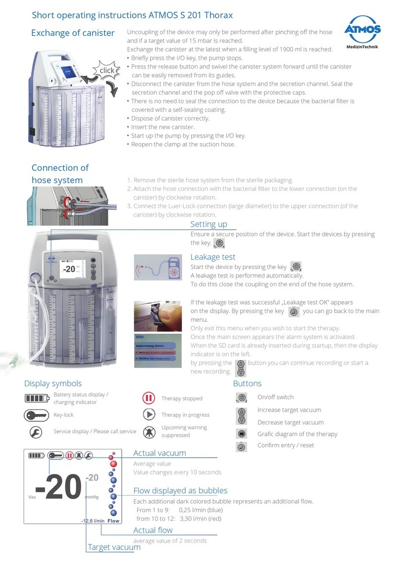
Atmos S 201 Thorax User manual

Atmos
Atmos Chair 41 Gyne User manual

Atmos
Atmos S 201 Thorax User manual
Atmos
Atmos C 31 User manual
Atmos
Atmos Record 55 DDS User manual

Atmos
Atmos S 351 User manual
Atmos
Atmos S 201 Thorax User manual

