TBB idSWITCH LMP1218-PWM User manual
LMP1218-PWM Master Power Unit User Manual
IDM Technologie
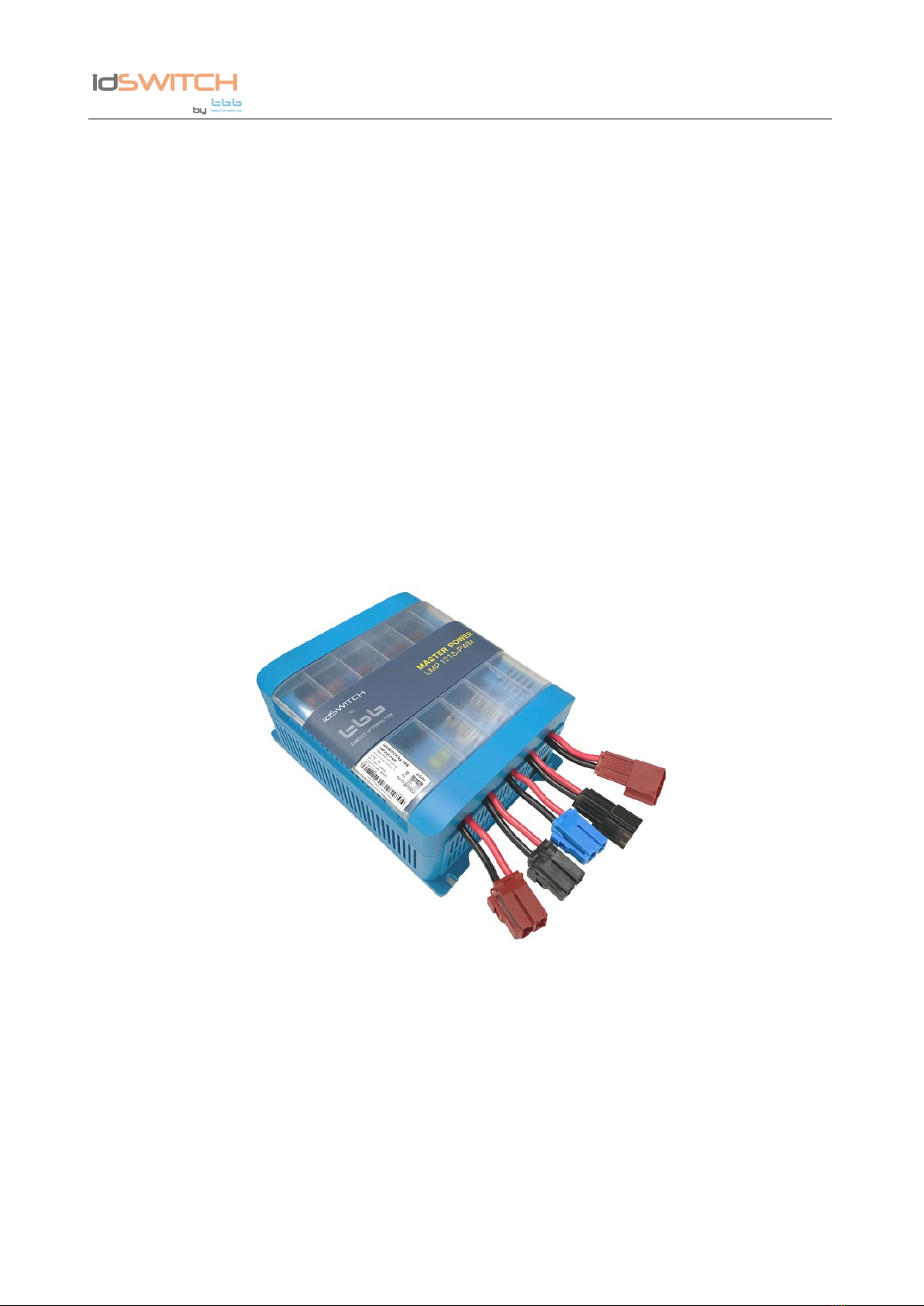
LMP1218-PWM
Master Power Unit
Version
:
A1.0
Date: Apr. 2020
LMP1218-PWM Master Power Unit User Manual
IDM Technologie
WARNING : FIRE HAZARD
SUITABLE FOR MOUNTING ON CONCRETE OR OTHER
NON- COMBUS TABLE SURFACE ONLY
CAUTION : THE DC AND AC BREAKER MUST HAVE BEEN
TURNED OFF BEFORE SERVICING
MADE IN CHINA

LMP1218-PWM Master Power Unit User Manual
IDM Technologie
D
Di
is
sc
cl
la
ai
im
me
er
r
Unless specially agreed in writing, IDM Technologie.
Ø Take no warranty as to the accuracy, sufficiency of suitability of any technical or other
information provided in this manual or other documentation.
Ø Assumes no responsibility or liability for loss or damage, whether direct, indirect,
consequential or incidental, which might arise out of the use of such information
Ø IDM Technologie offer standard warranty with its products, taking no responsibility for direct
or indirect loss due to equipment failure.
A
Ab
bo
ou
ut
t
t
th
hi
is
s
M
Ma
an
nu
ua
al
l
This manual describes our product features and provides procedure of installations. This manual
is for anyone intending to install our equipment.
G
Ge
en
ne
er
ra
al
l
I
In
ns
st
tr
ru
uc
ct
ti
io
on
n
Thanks for choosing our products and this manual were suitable for LMP1218-PWM Master Power
Unit.
This chapter contains important safety and operation instructions. Read and keep this User Guide
well for later reference.
The LMP1218-PWM Master Power Unit needs to be installed by professionals and please pay
attention to the following points prior to installation:
1> Please check the input voltage or voltage of battery is same to the nominal input voltage of this
unit.
2> Please connect positive terminal “+” of battery to “+” input of this unit.
3> Please connect negative terminal “-” of battery to “-” input of this unit.
4> Please use the shortest cable to connect and ensure the secure connection.
5> While connecting, please secure the connection and avoid short cut between positive terminal
and negative terminal of battery, which will cause damage of battery.
6> This unit will have high voltage inside. Only authorized electrician can open the case.
7> This unit WAS NOT designed to use in any life retaining equipment.

LMP1218-PWM Master Power Unit User Manual
IDM Technologie
I
In
nd
de
ex
x
1. General Safety Instruction..................................................................................................................................1
1.1 Safety Instruction .........................................................................................................................................1
1.2 General Precaution.......................................................................................................................................1
1.3 Precaution regarding battery operation ........................................................................................................1
2. LMP1218-PWM INTRODUCTION..................................................................................................................2
2.1 Features........................................................................................................................................................2
2.2 LED Display................................................................................................................................................3
3. KEY FEATURES AND FUNCTIONS ..............................................................................................................4
3.1 Multiple inputs.............................................................................................................................................4
3.2 Battery Charger of Auxiliary Battery...........................................................................................................4
3.3 Power Supply Mode ....................................................................................................................................5
3.4 PWM Solar charger controller.....................................................................................................................5
3.5 Voltage Charging Relay (VCR ) ..................................................................................................................5
3.6 Battery Low Voltage Protection (BLVP) .....................................................................................................5
3.7 Manual Battery Switch ................................................................................................................................ 5
3.8 DC Distribution ...........................................................................................................................................6
4. STRUCTURE AND INSTALLATION..............................................................................................................7
4.1 LMP1218-PWM Master Power Unit...........................................................................................................7
4.2 Installation ...................................................................................................................................................9
4.3 Fuse specification ......................................................................................................................................10
5. OPERATION ...................................................................................................................................................12
5.1 Configuration on LMP1218-PWM............................................................................................................12
5.1.1 Dip switch setting...................................................................................................................................12
5.1.2 External Battery Switch(RSW) ..............................................................................................................13
5.2 Daily Maintenance.....................................................................................................................................14
6. Trouble shooting ..............................................................................................................................................15
6.1 LED display on LMP Unit.........................................................................................................................15
7. Specification.....................................................................................................................................................16

LMP1218-PWM Master Power Unit User Manual
IDM Technologie
1
1. General Safety Instruction
1.1 Safety Instruction
As dangerous voltages and high temperature exist within the LMP1218-PWM Master Power Unit,
only qualified and authorized maintenance personnel are permitted to open and repair it. Please
make sure the unit is turned off before open and repair it.
This manual contains information concerning the installation and operation of LMP1218-PWM
Master Power Unit. All relevant parts of the manual should be read prior to commencing the
installation. Please follow the local stipulation meantime.
Any operation against safety requirement or against design, manufacture, safety standard, and are
out of the manufacturer warranty.
1.2 General Precaution
1.2.1 Do not expose to dust, rain, snow or liquids of any type,it is designed for indoor use. DO
NOT block off ventilation, otherwise the LMP1218-PWM Master Power Unit would be
overheating.
1.2.2 To avoid fire and electric shock,make sure all cables selected with right gauge and being
connected well. Smaller diameter and broken cable are not allowed to use.
1.2.3 Please do not put any inflammable goods near to this unit.
1.2.4 Never place this unit directly above batteries, gases from a battery will corrode and damage
LMP1218-PWM Master Power Unit.
1.2.5 Do not place battery over LMP1218-PWM Master Power Unit.
1.3 Precaution regarding battery operation
1.3.1. Use plenty of fresh water to clean in case battery acid contacts skin, clothing, or eyes and
consult with doctor as soon as possible.
1.3.2. The battery may generate flammable gas during charging. NEVER smoke or allow a spark
or flame in vicinity of a battery.
1.3.3. Do not put the metal tool on the battery, spark and short circuit might lead to explosion.
1.3.4. REMOVE all personal metal items such as rings, bracelets, necklaces, and watches while
working with batteries. Batteries can cause short-circuit current high enough to make metal melt,
and could cause severe burns.

LMP1218-PWM Master Power Unit User Manual
IDM Technologie
2
2. LMP1218-PWM INTRODUCTION
2.1 Features
Ø Smart battery charger 12V18A
² Active PFC charging
² Temperature compensated Charging
² Voltage compensated Charging
Ø 16 Fused DC outputs, including water pump and lighting central control.
Ø Battery charging relay 12V 30A
Ø Battery Low Voltage Protection
Ø Built in Battery Switch to isolate the battery when in storage
Ø Support external remote battery switch
Ø Control one water pump with two tank probes
Ø Solar charger controller(PMW), 15A
LMP1218-PWM Master Power Unit User Manual
IDM Technologie
3
2.2 LED Display
Ta ble 1 LED indication
NO.
LED
Color
Status
Description
1
CHG
Green
ON
Battery charged
Flashing
(flash once every second)
Battery charging
OFF
Battery discharge
2
Dischg
Orange
ON
Battery discharging
OFF
Battery charging
3
CHG/ Dischg
Green/Orange
Both ON
Power supply
LMP1218-PWM Master Power Unit User Manual
IDM Technologie
4
3. KEY FEATURES AND FUNCTIONS
3.1 Multiple inputs
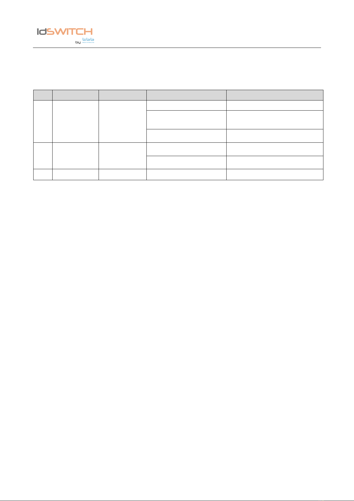
LMP master power unit may have multiple sources at one time. These sources include the Shore
power, Solar panel and Alternator (Motor battery). There is priority among these sources, but LMP
allows several sources to charge auxiliary battery at the same time. The priorities are listed below.
Ta ble 2 Energy sources priority
AC Mains
✓
✓
✓
Solar panel
✓
✓
✓
✓
Alternator (Motor
battery)
✓
✓
✓
Dominating Source
AC mains +
Solar panel
AC mains +
Solar panel
AC mains
Alternator +
Solar panel
Solar panel
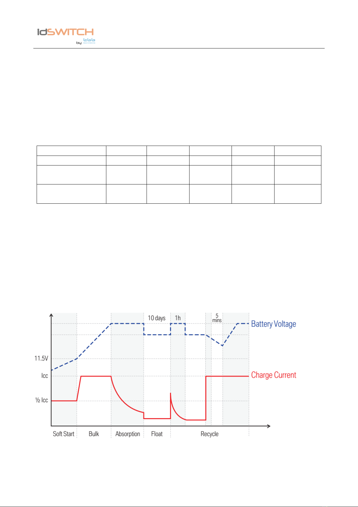
3.2 Battery Charger of Auxiliary Battery
The charger automatically starts when the appropriate qualified power is connected, either from
grid, generator. With multiple charging stages (soft start-bulk absorption float-recycle),
LMP1218-PWM is designed to fully charge battery quickly. To guarantee the optimal charging for
batteries of different states, the LMP1218-PWM features Microprocessor-controlled charging
algorithm. The Float and Recycle charging programs guarantees the battery being charged
properly upon being connected for a longer period.
Figure 1 Charging algorithm for lead-acid battery
Lithium battery charging

LMP1218-PWM Master Power Unit User Manual
IDM Technologie
5
The LMP1218-PWM can be configured to charge Lithium battery.
3.3 Power Supply Mode
If no battery is attached to LMP1218-PWM unit, it will work as a power supply automatically with
a 12.8VDC output.
3.4 PWM Solar charger controller
LMP has a built-in PWM charger for the service battery.
² Max open voltage is 25VDC
² Max supply current is 15A
3.5 Voltage Charging Relay (VCR )
LMP1218-PWM Master Power Unit has a built-in voltage charging relay (VCR), which can get
power from alternator to supply the system whilst the engine is running.
LEAD ACID BATTERY -- When the motor battery reaches 13.4VDC with threshold time delay, the
VCR will be engaged to allow power from alternator to supply the system. VCR will continue
being engaged until the motor battery’s voltage drops under 12.8VDC.
LiFePO4 LITHIUM BATTERY -- When the motor battery reaches 14.0VDC with threshold time
delay, the VCR will be engaged to allow power from alternator to supply the system. The VCR will
continue being engaged until the motor battery’s voltage drops under 13.5VDC.
The VCR will be disengaged when the auxiliary battery’s voltage reached 14.8V.
NOTE: If vehicle is fitted with a smart charging system (Variable Voltage or Temperature
Compensating), the VCR charge system may not function correctly and a DC-DC Charging
system is recommended
Please consult your local dealer or installer for further information.
3.6 Battery Low Voltage Protection (BLVP)
LMP1218-PWM master power unit has a built-in low voltage protection relay. It will disconnect
the load once the battery voltage drops below the threshold voltage. The default setting is
10.8VDC.
3.7 Manual Battery Switch
The LMP1218-PWM unit offers a convenient way to switch off the output of the auxiliary battery
LMP1218-PWM Master Power Unit User Manual
IDM Technologie
6
on-board. It protects the auxiliary battery from being drained by electronics on board, completely
isolating the battery.
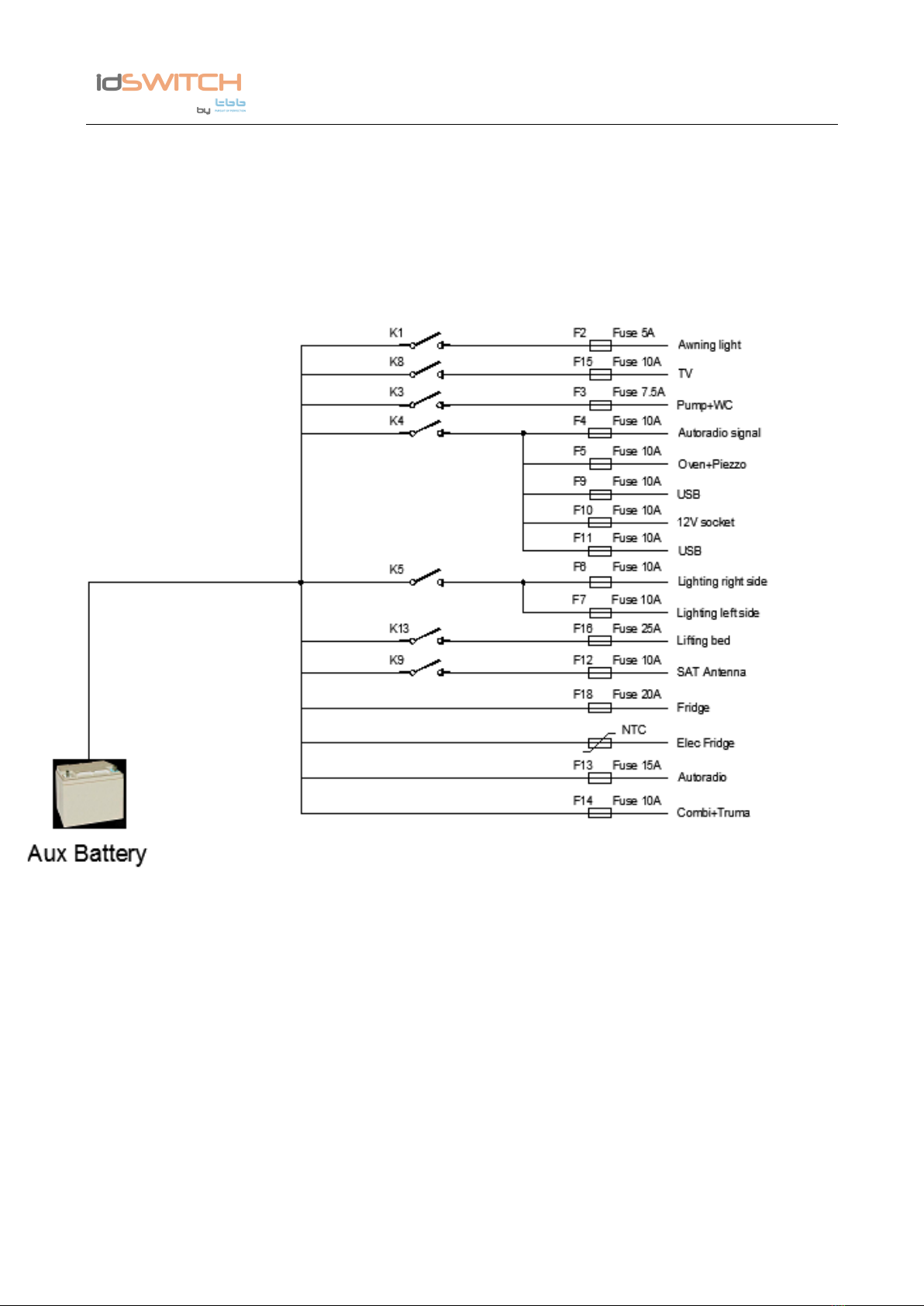
3.8 DC Distribution
Figure 2 DC distribution schematic diagram
LMP1218-PWM Master Power Unit User Manual
IDM Technologie
7
4. STRUCTURE AND INSTALLATION
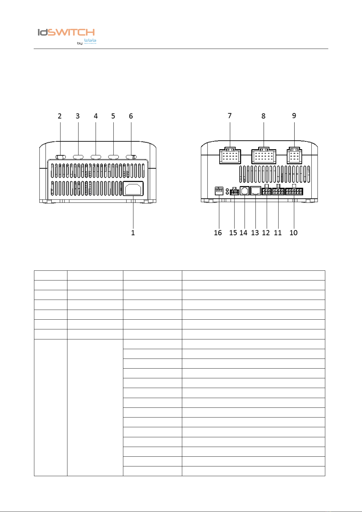
4.1 LMP1218-PWM Master Power Unit
Figure 3 Connectors at front and back
Ta ble 3 Connector description
No.
DEFINITION
LABEL
DESCRIPTION
1
AC input port
/
AC input port
2
/
PV
Connect to PV Panel
3
/
Fridge
Connect to fridge
4
/
Lifting Bed
Connect to lifting bed
5
/
Motor BAT
Connect to Motor BAT
6
/
AUX BAT
Connect to AUX BAT
7
Loads
[1]1
POS : Awning lamp
[1]2
GND :
[1]3
POS : Info D+ Fridge
[1]4
POS : Side lights
[1]5
GND : Side lights
[1]6
POS : Info D+ SAT antenna
[1]7
POS : Pump + WC
[1]8
GND : Pump + WC
[1]9
POS : Info D+ Preheating pump
[1]10
POS : Autoradio Signal
[1]11
GND :
[1]12
GND :
[1]13
POS : Oven + Piezzo
[1]14
GND : Oven +Piezzo

LMP1218-PWM Master Power Unit User Manual
IDM Technologie
8
[1]15
GND : Buzzer Footstep
8
Loads
[2]1
POS : Lighting Right side
[2]2
GND : Lighting Right side
[2]3
POS : Buzzer Footstep
[2]4
POS : Lighting Left side
[2]5
POS : Lighting Left side
[2]6
GND: In/Out Footstep (COM)
[2]7
POS : Power Tablet
[2]8
GND : Power Tablet
[2]9
Out Footstep (Normally Open)
[2]10
POS + Lifting bed
[2]11
GND - Lit électrique
[2]12
In Footstep (Normally Open)
[2]13
POS + Plug 12V Kitchen
[2]14
GND - Plug 12V Kitchen
[2]15
M1 - Footstep
[2]16
POS + Plug USB Kitchen/Bedroom
[2]17
GND - Plug USB Kitchen/Bedroom
[2]18
Footstep
9
Loads
[3]1
POS : Permanent Autoradio
[3]2
GND :
[3]3
POS : SAT antenna
[3]4
POS : Combi + TRUMA/ALDE control
[3]5
GND : Combi + TRUMA/ALDE control
[3]6
GND : Elec Fridge
[3]7
POS : TV
[3]8
GND : TV
[3]9
POS : Elec. Fridge
10
Signal terminal
[7]1
D+ (active high +BAT
[7]2
Switch ON/OFF (Main)
[7]3
D+ (active down GND)
[7]4
[7]5
Sidelights (active high +BAT)
[7]6
+APC (active high +BAT)
[7]7
Sidelights (active down GND)
[7]8
+APC (active down GND)
[7]9
Switch ON/OFF (NO)
[7]10
Footboard End of stroke (COM)
[7]11
Footboard End of stroke (NO)
[7]12
11
Grey water tank
[6]1
CW-REF
[6]2
CW-25%
[6]3
CW-50%
[6]4
CW-75%
LMP1218-PWM Master Power Unit User Manual
IDM Technologie
9
[6]5
CW-100%
[6]6
12
Fresh water tank
[5]1
CW-REF
[5]2
CW-25%
[5]3
CW-50%
[5]4
CW-75%
[5]5
CW-100%
[5]6
13
RS485 port
Connect to RS485 bus
14
CI Bus port
Connect to CI bus
15
Communication
port
[4]1
Wake-up
[4]2
GND
[4]3
GND
[4]4
+12V
[4]5
CAN H
[4]6
CAN L
16
DIP Switch
1 VCR
Set the battery type, VCR and Mode
2 Mode
3 Bat type
4 Bat type
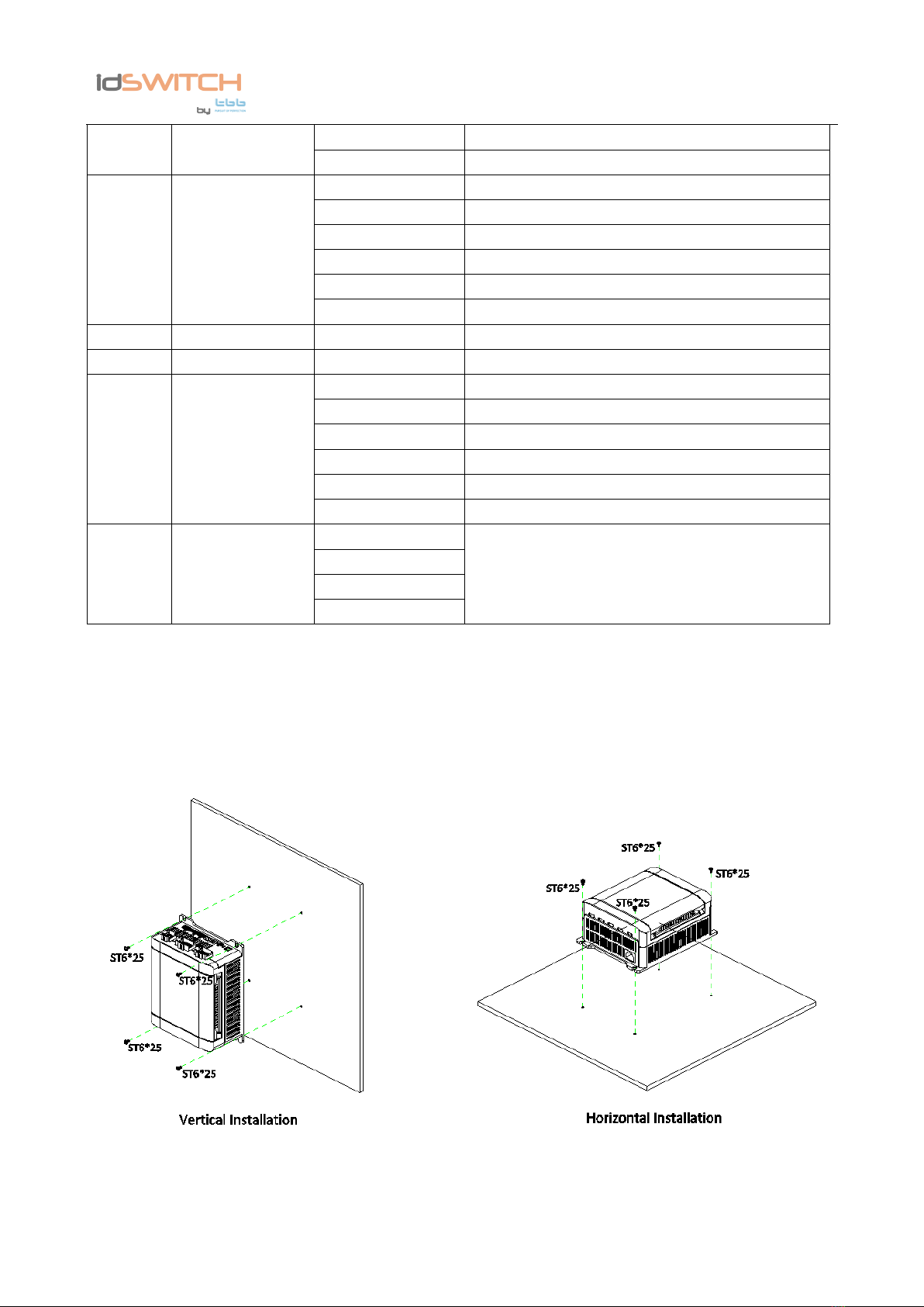
4.2 Installation
Ensure the space (at least 3-5cm on the left and right side) beside the LMP1218-PWM unit for the
good ventilation.
Figure 4 Installation

LMP1218-PWM Master Power Unit User Manual
IDM Technologie
10
Figure 5 Dimensions of LMP1218-PWM
4.3 Fuse specification
Here is a list for the fuses installed on LMP1218-PWM. Please also take reference of Figure 2.

LMP1218-PWM Master Power Unit User Manual
IDM Technologie
11
Ta ble 4 Fuse specification list
Fuse No.
DC loads
Specification
F2
Awning light
5A
F3
Pump
7.5A
F4
Auxiliarie
10A
F5
Oven
10A
F6
Lighting 1
10A
F7
Lighting 2
10A
F9
USB Socket Bedroom
10A
F10
USB Socket Kitchen
10A
F11
12V Socket Kitchen
15A
F12
Permanent SAT Antenna
10A
F13
Permanent Autoradio
5A
F14
Permanent Heating System
10A
F15
Permanent TV-Demodulator
10A
F16
Lifting Bed
25A
F18
Permanent Fridge
20A
F19
Footboard
20A
F20
AUX BAT
50A
F21
Motor BAT
50A
F1
By-pass Pump
25A
F8
By-pass Lighting
25A
F17
By-pass Lifting
25A
LMP1218-PWM Master Power Unit User Manual
IDM Technologie
12
5. OPERATION
5.1 Configuration on LMP1218-PWM
You could set the battery type, VCR and Mode through LMP1218-PWM master power unit.
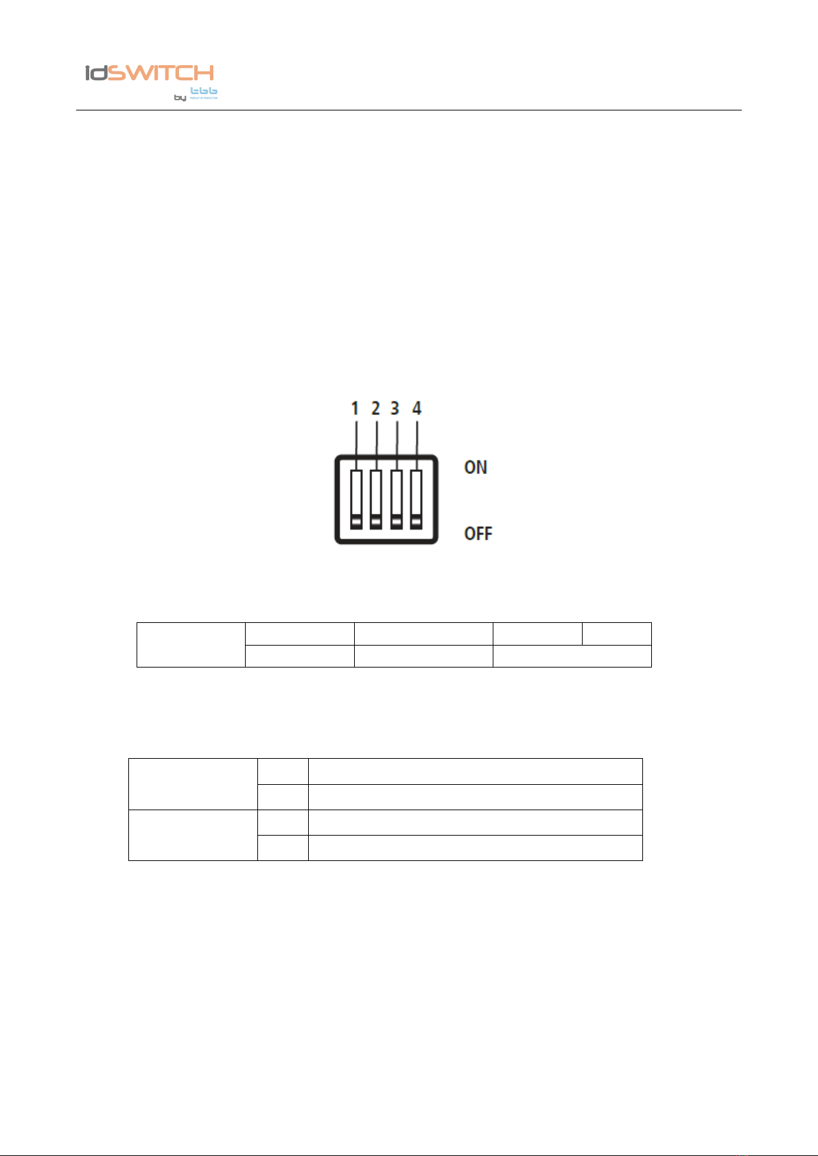
5.1.1 Dip switch setting
There are dip switches for you to set VCR mode, Working mode and Battery type.
Figure 6 Dip switch
Ta ble 5 Dip switch definition
5.1.1.1 Dip switch for VCR mode and Working mode
Ta ble 6 Dip switch for VCR mode and Working mode selection
a) VCR mode
There are two VCR modes for optional:
- Integrated VCR: when this mode is selected, the integrated VCR is activated, i.e. 18A
- Ex-DC / DC: When this mode is selected, the integrated VCR is deactivated; and an IDM NEMO
type external DC-DC booster can be connected to replace this integrated VCR
Caution If Booster set the VCR to ON and only for LEP lithium batteries
b) Working mode
There are two working modes for optional:
DIP SWITCH
1
2
3
4
VCR mode
Working mode
Battery type
VCR mode
off
Built-in VCR (Default setting)
on
Ex-DC/DC
Working mode
off
Charger (Default setting)
on
Power supply

LMP1218-PWM Master Power Unit User Manual
IDM Technologie
13
- Charger: When this mode is selected, the LMP will operate as a charger to charge the auxiliary
battery as long as the network or qualified PV is introduced
- Power supply: when this mode is selected, the LMP will produce a stable voltage of 12.8 Vdc to
power the connected DC loads
5.1.1.2 Dip switch for battery setting
Ta ble 7 Dip switch for battery type setting
Battery type
Position
3
Position
4
Battery type
off
off
AGM
off
on
GEL
on
off
LEP
on
on
WET
5.1.2 External Battery Switch(RSW)
LMP1218-PWM offers a possibility to connect with an external battery switch(RSW), which allows
user to turn on/off the auxiliary battery output remotely.
Figure 7 Battery switch
Figure 8 Wiring diagram of battery switch
Battery Switch

LMP1218-PWM Master Power Unit User Manual
IDM Technologie
14
5.2 Daily Maintenance
• Confirm the Battery Switch is switching on when you want to charge the battery with the AC
grid.
• Check the nominal battery voltage is 12Vdc.
• When replacing the existing battery with a new one, please have the new battery fully charged
by Grid for the first time to calibrate a precise battery SOC.

LMP1218-PWM Master Power Unit User Manual
IDM Technologie
15
6. Trouble shooting
6.1 LED display on LMP-PWM Unit
Tab le 8 Error LED indicator of LMP-PWM
NO.
LED
Color
Status
Description
1
CHG /
DISCHG
Green
/ Orange
Flash once per cycle
Service battery voltage low
2
Flash twice per cycle
Service battery voltage high
3
Flash 3 times per cycle
LMP-PWM unit Over temp
4
Flash 4 times per cycle
Bulk charge timeout
LMP1218-PWM Master Power Unit User Manual
IDM Technologie
16
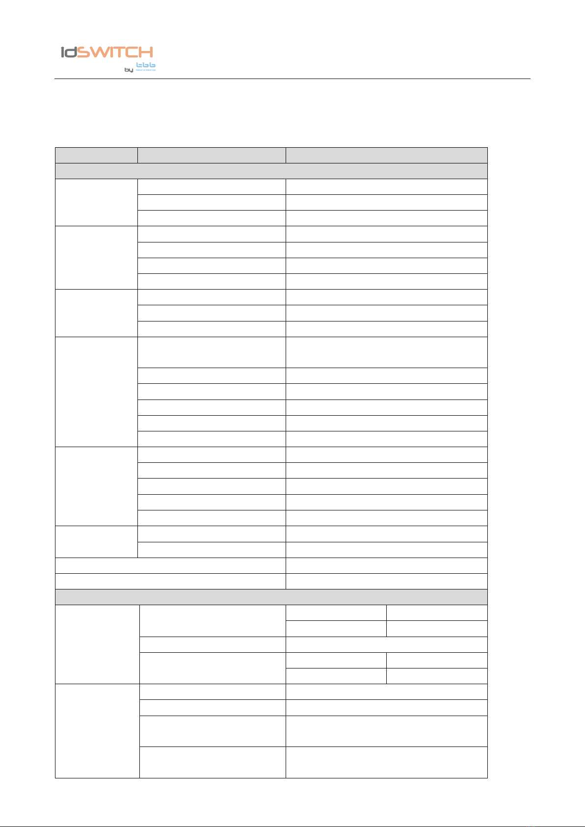
7. Specification
Tab le 9 Specification of LMP-PWM
Model
LMP1218-PWM
Electrical Specifications
AC Power
Nominal input voltage (V)
230±10%VAC 50/60Hz
Power factor
0.98
Input current at full load
1.3A
Battery
Starter battery
12Vdc
Starter battery voltage range
12.8-14.8Vdc
Service battery
12Vdc
Service battery voltage range
10.8-16.2Vdc
Solar Panel
Charger type
PWM
Open circuit voltage
25Vdc
Max supply current
15A
Charging Relay
Relay specification
12Vdc 30A continuous,
peak current 50A
Connect voltage
13.4V
Connect delay time
10sec
Disconnect voltage
12.8V
Disconnect delay time
60sec
High voltage limit
14.8Vdc
Charger mode
Charge Algorithms
TBB premium II - 5steps
Battery type
AGM/GEL/LFP/WET
Bulk current
18A(Max)
Absorption voltage
(14.4/14.1/14.4/14.7)±0.2Vdc
Float voltage
(13.5/13.5/13.5/13.7)±0.2Vdc
Power supply
mode
Nominal output voltage
12.8±0.2Vdc
Rated output current
18A(Continuous)
Efficiency(Max)
88%
Working temperature
-20℃~+40℃
Others
Battery
Disconnect(LVD
)
Disconnect voltage
AGM/GEL/WET
10.8Vdc(default)
LFP
11.2 Vdc(default)
Delay off time
60sec
Reconnect voltage
AGM/GEL/WET
11.8Vdc(default)
LFP
12.2 Vdc(default)
Protection
Short circuit on output
Fuse blown
Reverse Polarity
Fuse blown
Overload protection
Derate the output until overload is
removed
Battery charger over
temperature
Shut down LMP-PWM
This manual suits for next models
1
Table of contents
Other TBB Power Supply manuals


