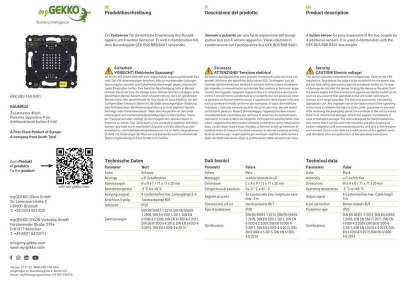
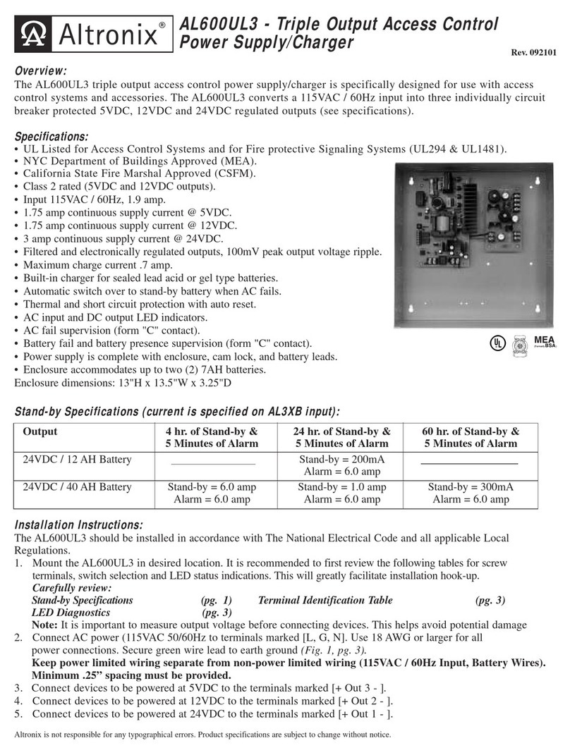
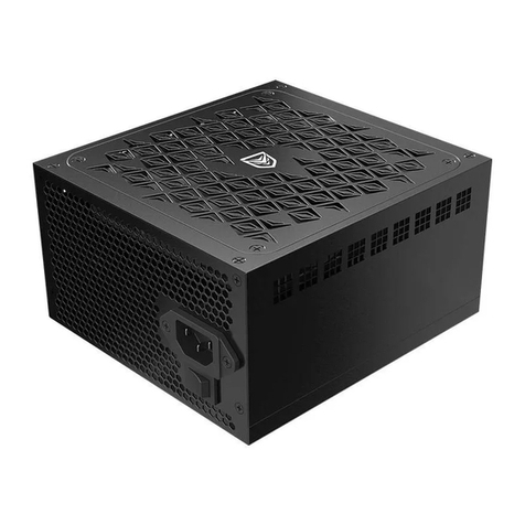
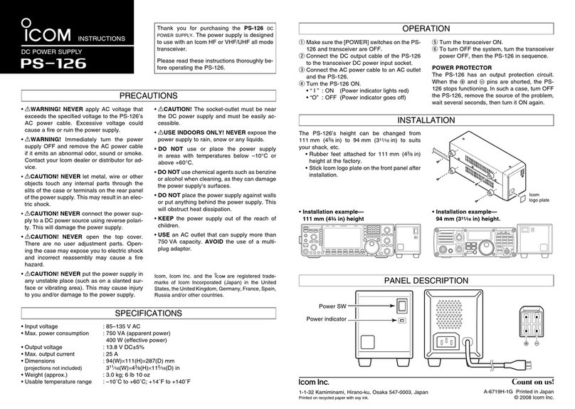
Film-Tech IREM EX-100GM3 Series User manual

Film-Tech
The information contained in this Adobe Acrobat pdf
file is provided at your own risk and good judgment.
These manuals are designed to facilitate the
exchange of information related to cinema
projection and film handling, with no warranties nor
obligations from the authors, for qualified field
service engineers.
If you are not a qualified technician, please make no
adjustments to anything you may read about in these
Adobe manual downloads.
www.film-tech.com

Electronic power supply
INSTALLATION AND OPERATION MANUAL
MAN01554E/1
IREM SpA Via Abegg 75 - 10050 Borgone Torino Italy - tel. ++39 0119648211 - fax ++39 0119648222 - E-mail: [email protected] - www.irem.it


3
MAN01554E/1
Caution !
You should read this manual before attempting any intervention inside the unit.
The noncompliance with the instructions given in this manual can lead to seri-
ous damage to the unit which in this case will invalidate the warranty.
No compensation or indemnity under any kind will be acknowledged for injury
or damage due to use or misuse of the product, for poor operation of the appli-
ances connected to IREM product or for immediate or indirect damage caused
to the powered equipment.
During the warranty period the replacement of defective parts and maintenance
procedures will be exclusively carried out at IREM servicing centre.
Keep this manual along with the unit.


5
MAN01554E/1
Description
Thiselectronicpowersupplyfor threephase208and400Vac50/60Hz input,hasbeen
designed to feed from 1000 to 3000W short arc Xenon lamps, meeting all the
requirements of lamp manufacturers to ensure correct operation, long life to the lamp,
and high reliability.
This compact and lightweight power supply has been designed to meet the require-
ments of a unit to be installed inside a cabinet.
Its particularly compact design, the advanced circuitry and the displacement of input
and output terminal board and the lamp current adjustment make the unit suitable to a
wide variety of applications both in vertical and horizontal position and specifically:
-film projection (traditional and digital applications)
-theatre applications
-architectural applications
-solar simulations.
The main characteristics of this power supply are:
- digital setting of parameters and operation modes,
- internal control of the delivered power
- two hour meters (total and partial)
- RS232 communication interface

MAN01554E/1 6
1. Input filter board
Limiting the high frequency interferences (complying with EMI/EEC Standards).
2. Diode bridge rectifier
Converting the alternated voltage from the mains into direct voltage
3. Inverter board
Designed in compliance with IGBT technology, H type full bridge configuration
4. High frequency transformer
Ensuring the galvanic insulation between input and output
5. Output rectifier circuit
Composed by two fast low noise diodes
6. Output filter
Ensuring the lamp ripple current value at ≤1.5% pk- pk.
7. Auxiliary powering board
8. µp board and controls
9. Synoptic board
Block diagram

7
MAN01554E/1
Technical characteristics
EX-100GM3-E EX-100GM3-US
400V version 208V version
Ordering code 00831031 00831036
Lamp capacity [W] 1000 to 3000
Input voltage range [V] 360-460 3ph 187-230 3ph
Input frequency [Hz] 50/60
Max. input current [A] 11 15
Sinusoidal absorption not provided
DC output current range [A] 30-110
DC voltage range [V] 17-34
DC max. output voltage at 110A [V] 31
Max. output power [W] 3400
No-load voltage range [V] 120-140
No-load voltage rising time [s] 3
Ripple [%] <1.5
Efficiency 0.87
Output overload protection electronic
Lamp striking soft-start ignition current
Input circuit protection fuse
Input extra voltage protection provided
Serial line protection*
optoisolator
Output current stabilisation provided
Synoptic panel LCD displaying: current, rated power, voltage
unit internal temperature,
operation hours (in total)
operation hours (for each lamp)
ON/OFF control keyboard, external switch, serial line
Lamp current adjustment keyboard, 0-10V signal, serial line
Remote control RS232 serial line - baud rate: 19200, parity: none
data bit: 8, communication protocol: IREM
Output signals lamp ON, alarms ON
Input signals 0-10V signal, emergency, ON/OFF remote
stand-by mode
Operating temperature [°C] 0 to +40
Storage temperature [°C] -20 to +60
Degree of protection IP20
Markings CE
Insulation class CL1
Ventilation forced
Dimensions [mm] 225 x 465 x 350h
Weight [kg] 19
* on request for both versions

MAN01554E/1 8
Functions and controls
Control devices
1. Input circuit protection
2. Ground terminal
3. Synoptic panel
4. Auxiliary terminal board
5. RS232 connector
6. Output terminal board

9
MAN01554E/1
Connection and operating information
Receiving the equipment
After receipt, check that the unit is in good condition. When necessary, contact the
forwarding agent.
Delivery arrangement
The supply consists of:
EX-100GM3... electronic power supply
plate for terminal protection
metal brackets
three spare fuses
serial line optocoupler + adapter 9/25 pin (on request)
synoptic panel
auxiliary connector
installation and operation manual
warranty card.
Storage
If the unit is stored before installation, check that it is kept dry and cannot come into
contact with water in any form. Do not expose the unit to the sun rays or other sources
of heat.
Package removing and handling
Remove the packing and keep it in case of future transportation needs.
Carefully lift the unit by means of its handles. Avoid any shock when moving.
Installation - environment
TheperformanceoftheEX-100GM3... electronicpowersup-
ply is guaranteed for a temperature range variable between
0°C and +40°C. Check that the place where the equipment
is to be installed is sufficiently ventilated to prevent the air
around the unit from exceeding this limit. Avoid dusty envi-
ronments.
Ensure that the ventilation slots are unobstructed.
To prevent blockages caused by excessive temperatures,
do not expose the unit to the sun rays or other sources of heat.
40°C max.

MAN01554E/1 10
Warnings
Caution: dangerous voltage inside the power supply. Disconnect the unit from
the mains before checking the internal components.
Prevent water, liquids in general and/or foreign objects from getting inside the
appliance (do not open the unit, contact IREM servicing centre !).
Installation must be carried out by trained personnel only.
This power supply must be installed inside a grounded cabinet provided with a
circuit breaker duly rated.
Important note: the fuse holder powering cables are located in the lower part of
the unit (see label on the front panel).
If the plant is provided with a residual current breaker having a tripping value of
30mA, this breaker could trip when switching on the power supply. This does
not normally mean a failure, but is due to the capacitors of the EMI filter. Switch
on the breaker again to alleviate the problem.
Feet mounting
EX-100GM3... electronic power supply is equipped with two fixing brackets that may
be used as an anchoring for the unit (B) or as normal feet when the unit is normally
displaced without any fixing (A).
Connection and operating information

11
MAN01554E/1
Connection and operating information
Feet mounting
If feet are used as fixing flanges, holes have to be done as per following picture:

MAN01554E/1 12
Connection and operating information
Mounting the synoptic panel
The unit is fitted with a synoptic panel, vertically mounted onto the front panel (pict.
no. 1).
Directions for horizontal mounting:
Please follow the instructions below to place the synoptic panel horizontally (pict. no.
2):
-Take off the synoptic panel on the front panel by releasing the two fixing screws;
-Unscrew the four screws fixing the metal plate that supports the sub-D 15 pin fe-
male connector
-Rotate (90°) the metal plate supporting the sub-D 15 pin female connector
-Screw the four screws again to fix the metal plate
-Place the synoptic panel in its housing and tighten the two screws again.
Pict. no. 1 Pict. no. 2

13
MAN01554E/1
Connection and operating information
Preliminary checks
The connection must be carried out in compliance with the current safety stand-
ards. To ensure a correct operation of the unit, please strictly follow these rec-
ommendations:
-the input powering has to be:
400V version: 360-460V, 50/60Hz plus ground, withstanding a current of 11A per
phase
208V version: 187-230V, 50/60Hz plus ground, withstanding a current of 15A per
phase
-the earth installation must comply with current standards
-the cables to be connected to the output terminals must have a size suitable to the
lamp power.
During connection pay attention to the lamp polarity.
Important note: the ground connection of the power supply must be equipotential
with respect to the ground connection of the lamphouse. To do this, perform a
connection between the ground (PE) of the power supply and the ground of the
lamphouse (cable length: 400 mm max.).
Connecting input/output cables
Connect the input/output cables to the relevant terminal board.
Pay attention to lamp polarity and terminal identification:
Input terminals Output terminals
U-V-W: phases +: positive
PE: ground -:negative
After having performed the cable connection, take in place the protective plate (see
directions on next page).

MAN01554E/1 14
Connection and operating information
Directions for inserting the protective plate
Mount the metal protective plate as per following steps:
- be sure the unit is not powered
- loose the fixing screws (B) located on the front panel (bottom)
- take in place the plate
- tighten the screws (B) of the protective plate
- check the earth connection.

15
MAN01554E/1
Connection and operating information
Auxiliary terminal boards
When using the remote control perform connections through J4 terminal board or J3
connector placed on the front of the unit.
Important note: different connections may cause dangerous failures
to the unit !
J3 connector
RS-232 serial port for remote control
We recommend to protect the input serial line by means of a galvanic
insulator (on request) to avoid damages to the PC during the igniter dis-
charge. This protection has to be connected to the PC directly.
J4 terminal board
1-2 (INPUT) 0-10V analog input for lamp current monitoring (under Ext_10V mode)
3-4 (INPUT) ON/OFF remote
Input for lamp striking under manual mode (from remote control)
and Ext_10V mode (close the contact to strike the lamp)
5-6 (INPUT) Input for switching off the power supply in emergency
(insert a jumper, if not used)
7-8 (OUTPUT) Lamp ON output (normally open dry relay contact - 30V 1A max.)
9-10 (OUTPUT) Alarms ((normally open dry relay contact - 30V 1A max.)
11-12 (INPUT) Stand-by
(close down this contact to have the stand-by lamp current previously entered)
The connection cables to terminals 3-4 (remote), 5-6 (emergency) and 1-2 (0-10V
analogue input) have to be twisted and as short as possible.

MAN01554E/1 16
Thanks to the microprocessor control some safety functions, related to the power sup-
ply and the lamp connected to it, have been improved.
The max. power is one of the parameters that now can be set. During the operation,
the power supply checks that the delivered power does not exceed the preset value.
When exceeding, it reduces the delivered current down to a power (voltage by cur-
rent) equal or lower that the preset limit.
If the preset power value is referred to the lamp in use, an automatic control of the
max. power applied to the lamp will be obtained. The default value (3400W) aims at
protecting the power supply.
The synoptic panel allows to set/change the different operation modes (factory set-
ting: manual mode).
The possibility to set different operating modes permits an optimum use of the power
supply avoiding incorrect use.
The operation modes are exclusive i.e. when a mode has been entered, the others will
be automatically ignored (i.e. if the RS232 mode has been entered, then possible
commands from synoptic panel or from 0-10V analogue input will be automatically
ignored).
The operation modes are: manual from synoptic panel, manual from remote control,
through serial line and through 0-10V analogue input.
Two hour meters (total and partial lamp operating hours) are located on the synoptic
panel. The first one (total operating hours) cannot be reset.
A remote contact (J4, pins 11-12) activates the stand-by mode. Under this mode the
delivered current corresponds to the value set in “input parameters”. This mode is
useful during the projection timeout if the lamp must stay on. This contact can be
activated under any operation mode.
What’s new
Connection and operating information

17
MAN01554E/1
Connection and operating information
Parameter setting
For more detailed information, please refer to EX communication protocol on
sections: “programming the lamp parameters” and “behaviour to wrong lamp
parameters sent to bytes m.s.b. command data (dh) and dato l.s.b. command
data (dl) via RS232”.
Lamp Pmax : max. power of the lamp. When entered, an automatic control will avoid
exceeding this value. Factory setting: 3400W (corresponding to the max. power of the
power supply).
Lamp Imax (operating range: 30 - 110A): lamp max. admitted current. When entered,
an automatic control will avoid exceeding this value. Factory setting: 110A
When entering an Imax value lower than Imin , Imin will be the delivered current value.
Lamp Imin (operating range: 30 - 65A): lamp min. admitted current. When entered, an
automatic control will avoid exceeding this value. Factory setting: 30A
Lamp stand-by (operating range: Imax - Imin): lamp stand-by current when the contacts
11 and 12 of J4 have been closed. When the contacts have been closed, an automatic
control will change the current according to the admitted operating range. Factory
setting: 30A.
The stand-by mode can be also activated through the serial line.
Factory setting of the output current: 30A.
Remarks:
1) when entering an Imax value lower than Imin the message “ERROR, Imax < Imin -
value not accepted” will be displayed. Imin will be set to 30A (default). Enter a new Imin
value.
2) when entering a min. value exceeding 65A, 30A will be set as default value.

MAN01554E/1 18
Directions for use
Start-up
-Be sure the emergency terminals 5,6 on J4 are short circuited through a wire if
there is no emergency switch.
-If the switching on of the unit has to be performed remotely , insert a switch or two
N.O. dry relay contacts between terminals 3 and 4 on J4 (ON-OFF remote)
-Before switching on the unit, be sure that the input voltage corresponds to the one
shown on the data plate.
-The power supply must be ON for at least 10 seconds before activating the remote
operation through the RS232 serial line (PC typically).
Getting started
-Be sure the unit has been correctly connected to the mains supply and to the lamp.
-Power the unit.
-Select the operation mode (through serial line or synoptic panel). Otherwise the
default parameters (manual mode) will be ON.
-Enter the lamp parameters (according to the lamp type) through the serial mode or
thesynopticpanel. Otherwise the default parameters (i.e. the factory setting) will be
ON.
-Strike the lamp according to the preset operation mode.

19
MAN01554E/1
Functions and controls
Synoptic panel
The synoptic panel is formed by:
1) Display
2) LEDs
3) keys for programming/displaying purposes
In details:
1) Display
two 16-characters lines. It is useful for displaying menus, machine parameters and
measurements performed.
2) LEDs, lit to indicate
green LED input mains ON
yellow LED manual mode ON
yellow LED programming mode/remote commands ON
red LED Alarms ON
3) Program/display keys
Dual-function keys, according to the check or setting modes selected through the
synoptic panel.
This manual suits for next models
2
Table of contents
