CP-08-01
SAFETY PRECAUTIONSSAFETY PRECAUTIONS
SAFETY PRECAUTIONSSAFETY PRECAUTIONS
SAFETY PRECAUTIONS
Before operating, maintaining or servicing any
ITW Ransburg coating system, read and
understand all of the technical and safety literature
for your ITW Ransburg products. This manual
contains information that is important for you to
know and understand. This information relates to
USER SAFETY and PREVENTING EQUIPMENT
PROBLEMS. To help you recognize this
information, we use the following symbols. Please
pay particular attention to these sections.
A WARNING! states information to alert youA WARNING! states information to alert you
A WARNING! states information to alert youA WARNING! states information to alert you
A WARNING! states information to alert you
to a situation that might cause serious injuryto a situation that might cause serious injury
to a situation that might cause serious injuryto a situation that might cause serious injury
to a situation that might cause serious injury
if instructions are not followed.if instructions are not followed.
if instructions are not followed.if instructions are not followed.
if instructions are not followed.
A CAUTION! states information that tellsA CAUTION! states information that tells
A CAUTION! states information that tellsA CAUTION! states information that tells
A CAUTION! states information that tells
how to prevent damage to equipment or howhow to prevent damage to equipment or how
how to prevent damage to equipment or howhow to prevent damage to equipment or how
how to prevent damage to equipment or how
to avoid a situation that might cause minorto avoid a situation that might cause minor
to avoid a situation that might cause minorto avoid a situation that might cause minor
to avoid a situation that might cause minor
injury.injury.
injury.injury.
injury.
A NOTE is information relevant to theA NOTE is information relevant to the
A NOTE is information relevant to theA NOTE is information relevant to the
A NOTE is information relevant to the
procedure in progress.procedure in progress.
procedure in progress.procedure in progress.
procedure in progress.
While this manual lists standard specifications
and service procedures, some minor deviations
may be found between this literature and your
equipment. Differences in local codes and plant
requirements, material delivery requirements, etc.,
make such variations inevitable. Compare this
manual with your system installation drawings
and appropriate ITW Ransburg equipment
manuals to reconcile such differences.
Careful study and continued use of this manual will
provide a better understanding of the equipment
and process, resulting in more efficient operation,
longer trouble-free service and faster, easier
troubleshooting. If you do not have the manuals
and safety literature for your Ransburg system,
contact your local ITW Ransburg representative
or ITW Ransburg.
SAFETYSAFETY
SAFETYSAFETY
SAFETY
> The user MUSTMUST
MUSTMUST
MUST read and be familiar
with the Safety Section in this manual and
the ITW Ransburg safety literature therein
identified.
>This manual MUSTMUST
MUSTMUST
MUST be read and thor-
oughly understood by ALLALL
ALLALL
ALL personnel who
operate, clean or maintain this equipment!
Special care should be taken to ensure that
the WARNINGSWARNINGS
WARNINGSWARNINGS
WARNINGS and safety requirements
for operating and servicing the equipment
are followed. The user should be aware of
and adhere to ALLALL
ALLALL
ALL local building and fire
codes and ordinances as well as NFPA-33NFPA-33
NFPA-33NFPA-33
NFPA-33
SAFETY STANDARDSAFETY STANDARD
SAFETY STANDARDSAFETY STANDARD
SAFETY STANDARD prior to installing,
operating, and/or servicing this equipment.
W A R N I N GW A R N I N G
W A R N I N GW A R N I N G
W A R N I N G
!!
!!
!
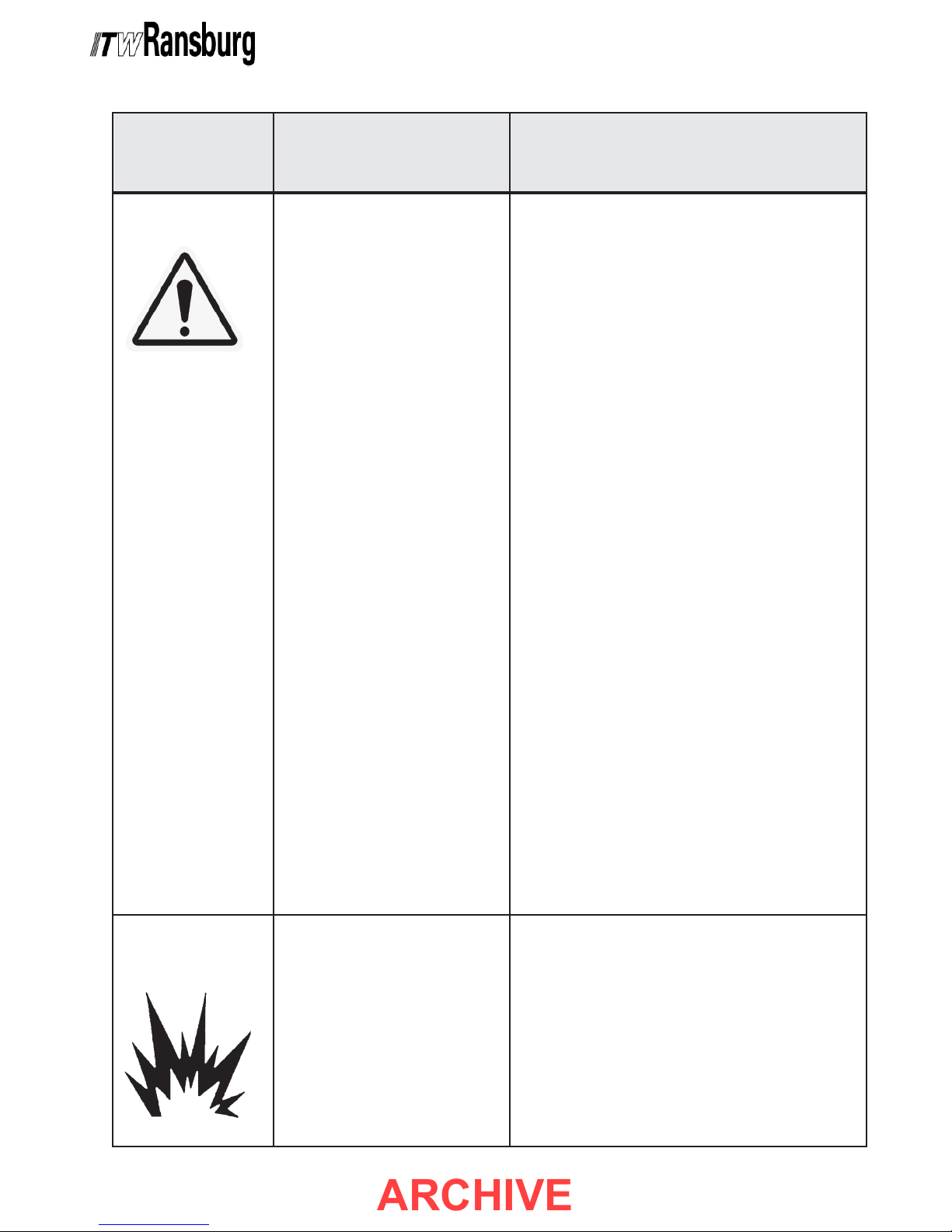
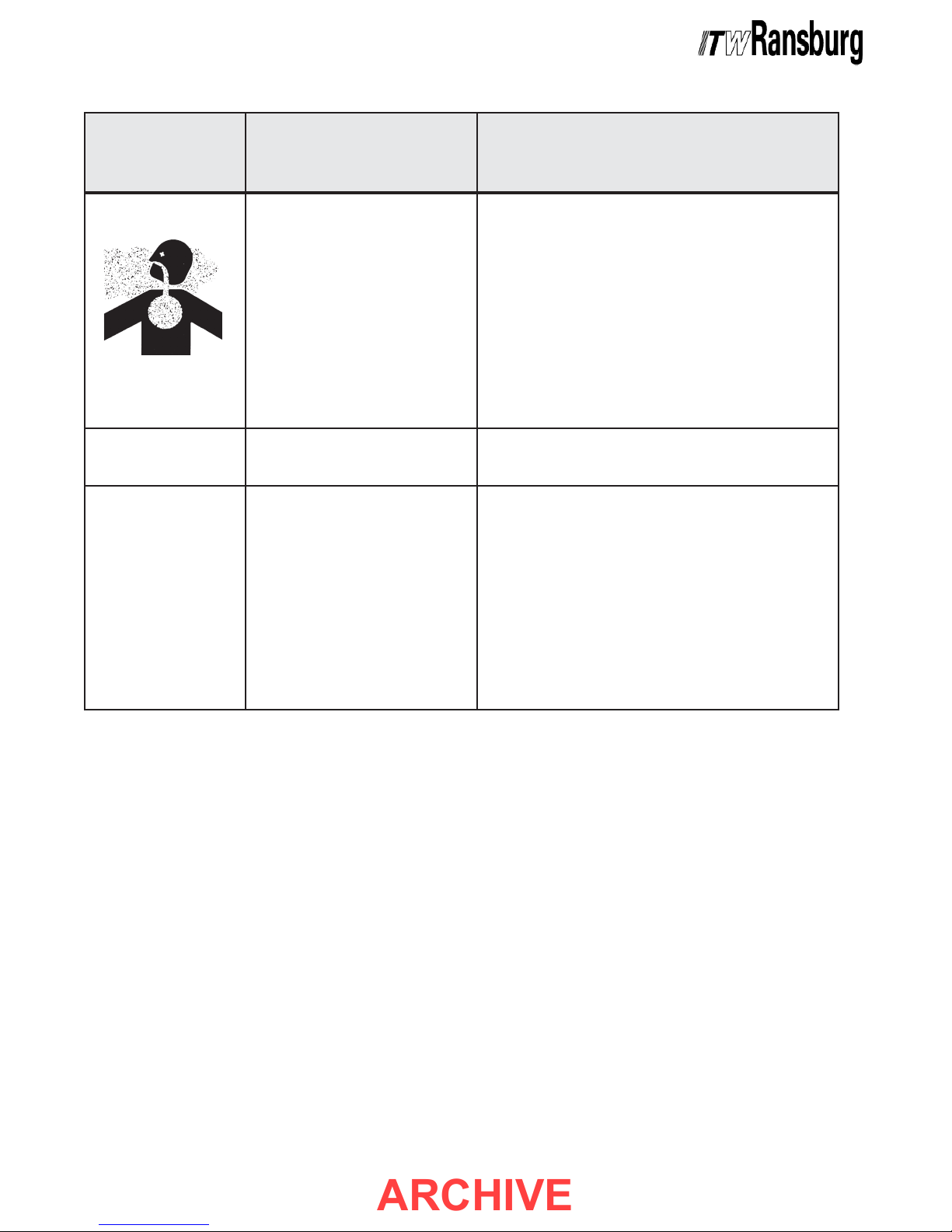
> The hazards shown on the following
page may occur during the normal use of
this equipment. Please read the hazard
chart beginning on page 2.
W A R N I N GW A R N I N G
W A R N I N GW A R N I N G
W A R N I N G
!!
!!
!
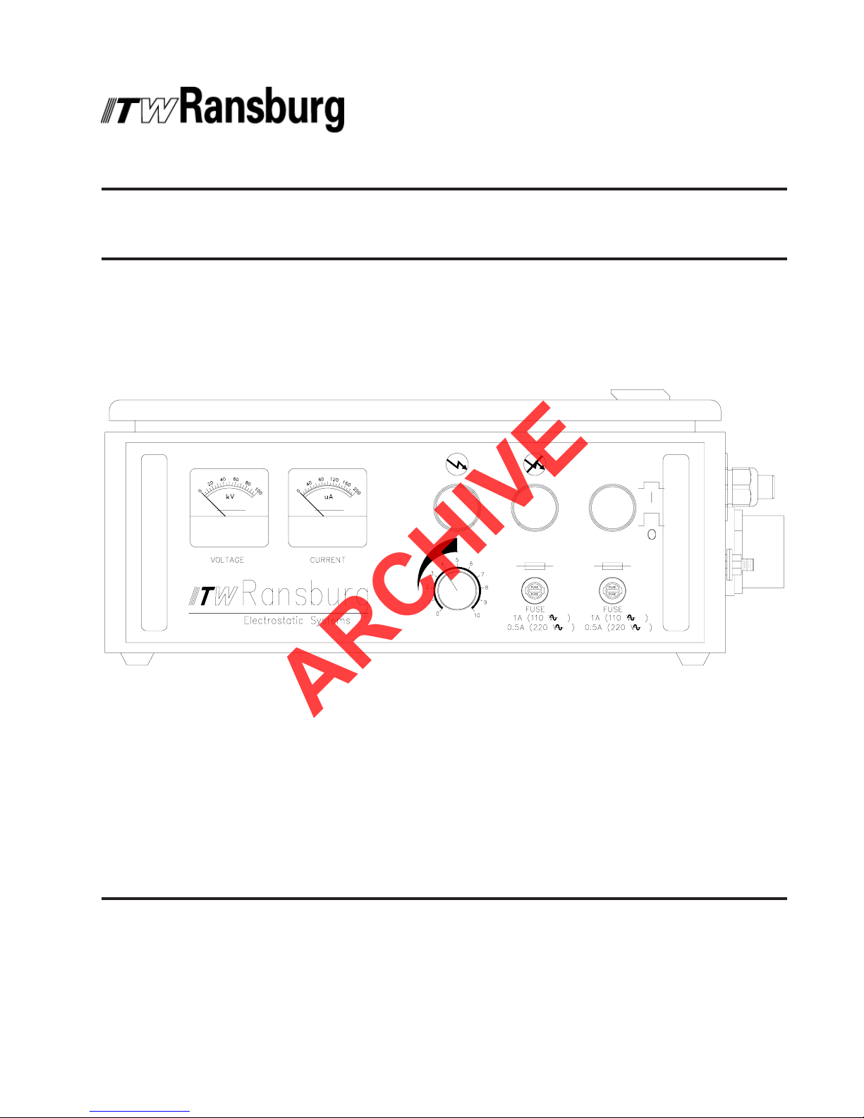
9040 Classic HV Power Supply - Safety
11
11
1