tbs electronics Discovery User manual

TBS DISCOVERY Quadrotor
Durable and crash resistant multirotor optimized for
dynamic FPV flight
Revision 2014-09-21
The TBS DISCOVERY quadcopter is a durable and crash resistant multirotor
optimized for dynamic FPV flight. By implementing the wiring into the frame,
the copter is easy to build and outperforms similar quads in terms of FPV
range and video link quality. It is perfect for all looking at a durable and
highly integrated FPV solution. The DJI Flame Wheel arms as predetermined
breaking point protect your electronics and are easily replaceable in the
field.
The TBS DISCOVERY comes as two main boards (top and bottom) and optional Flame Wheel arms with
accessories. It transforms the popular F450 (Flame Wheel) into a spider quadrotor. The GoPro and FPV camera
mount is placed ideally for "no-prop-in-view" pictures. The optional TBS CORE can be placed directly onto the
frame or we can install it for you.
Features
●TBS CORE pre-wired incl. sockets for Plug&Play VTx and FPV camera installation
●50A Current Sensor installed on the board, built for the TBS CORE or similar OSDs
●GoPro and FPV camera mounts
●Power Distribution Board (PDB)
●Traces and pads for clean R/C receiver to Flight Controller wiring
●RSSI trace to the TBS CORE
1

Before we begin
Thank you for buying a TBS product! The TBS DISCOVERY is a new multirotor aircraft from Team BlackSheep
(TBS) and features the best design practices available on the market to date, providing great flying stability and
incredible FPV characteristics.
Please read this manual carefully before assembling and flying your new TBS DISCOVERY quadrotor. Keep this
manual for future reference regarding tuning and maintenance.
Disclaimer
Our request to you; the aircraft may not be used to infringe on people's right to privacy. We have designed a toy
with mind blowing capabilities. It is your responsibility to use it reasonably and according to your experience
level. Use common sense. Fly safe. You are on your own. TBS has no liability for use of this aircraft.
●Locate an appropriate flying location
●Obtain the assistance of an experienced pilot
●Practice safe and responsible operation
●Always be aware of the rotating blades
●Prevent moisture
●Keep away from heat or excessive amounts of sunlight
2
Specifications
Type:
Asymmetric spider quadrotor
Airframe:
Reinforced black fiberglass (top RF transparent, bottom PDB)
Battery:
3S (11.1V) 5000 to 6000mAh or 4S (14.8V) 2500 to 4500mAh LiPo pack
Propellers:
9x5-inch or 10x5-inch (2xCW, 2xCCW)
Motor:
2212 or 2216 class, 700-900kV, 150-220W, 16x19 mm mount pattern
Speed controllers:
18 to 30A 400Hz Multirotor ESCs
Receiver:
5 channels or more
Flight controller:
Standard quadcopter controller with optional GPS module
Current sensor:
v1.1 100A, v1.2 and later 50A on-board
Center of Gravity:
15mm in front of Center of Thrust mark
Duration:
8 to 15min (dependent on drive train and battery system)
Distance:
up to 5km range (and return)
Altitude:
up to 2km / 6000ft
All-up-weight:
1400 to 2000g
Required tools
●Hex screwdrivers (2.0mm and 2.5mm)
●Soldering iron (50 to 100W recommended)
●Solder (Sn60Pb40 or Sn62Pb36Ag2, multicore flux)
●Propeller balancer (recommended)
3

Parts list
Before building your TBS DISCOVERY, make sure the following items are included in your kit.
1x Top frame plate
1x Bottom frame plate
1x Pilot camera mount plate
8x Red aluminum spacers
36x M3x6.5mm hex fitting screws
for spacers and motors
30x M2.5x5mm hex frame arm
screws
2x Pin headers for R/C (3x8 rows,
2.54mm pitch)
2x Pin header rows for TBS CORE
(2mm pitch)
2x VTx and camera Molex 1.00 to
1.25mm PicoBlade cables
Required parts
To get in the air the following equipment and parts are needed for assembly.
4x DJI Flame Wheel arms
4x 400Hz Multirotor Speed
Controller 18-30A
4x 750 to 900kV brushless motors
(incl. prop adaptor and mounting
screws)
4
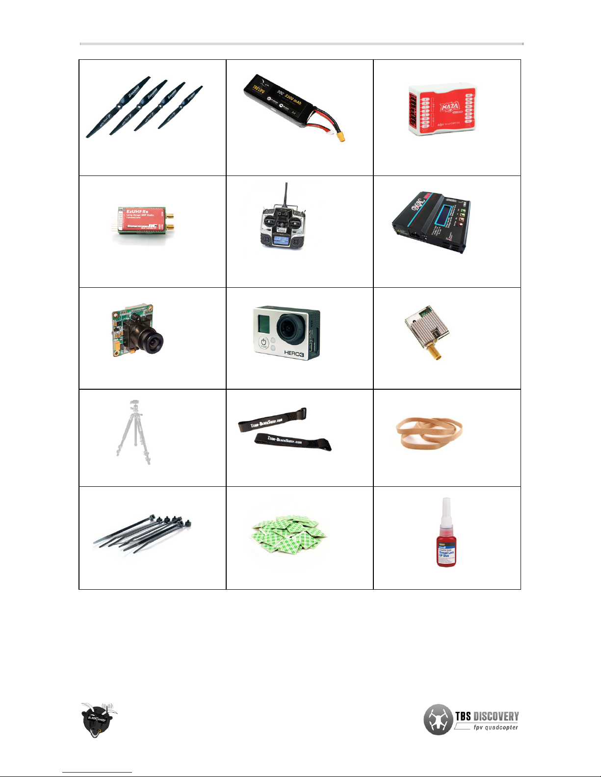
4x 9x5 or 10x5-inch propellers
(2xCW, 2xCCW)
1x 3S 5000 to 6000mAh or 4S 2800
to 4500mAh LiPo battery
1x Multicopter flight controller
1x R/C receiver (5-channels or
more)
1x R/C transmitter (5-channels or
more)
1x LiPo battery charger
1x Pilot camera (32x32mm)
1x HD recording camera
1x Video transmitter
1x Equipped ground station
2x Velcro battery straps
1x Rubber band
15x Zip-ties
2x Self-adhesive foam pads
1x Threadlock low strength
We offer most of these items on our website individually or as part of an
Almost-Ready-to-Fly
(ARF) and
STARTER kit. The equipment and parts we offer has been truly tried-and-tested to meet our standards for an
excellent flight experience. But you can of course replace these with equal or similar type. See the parts list at
the end of this manual for recommendations.
5
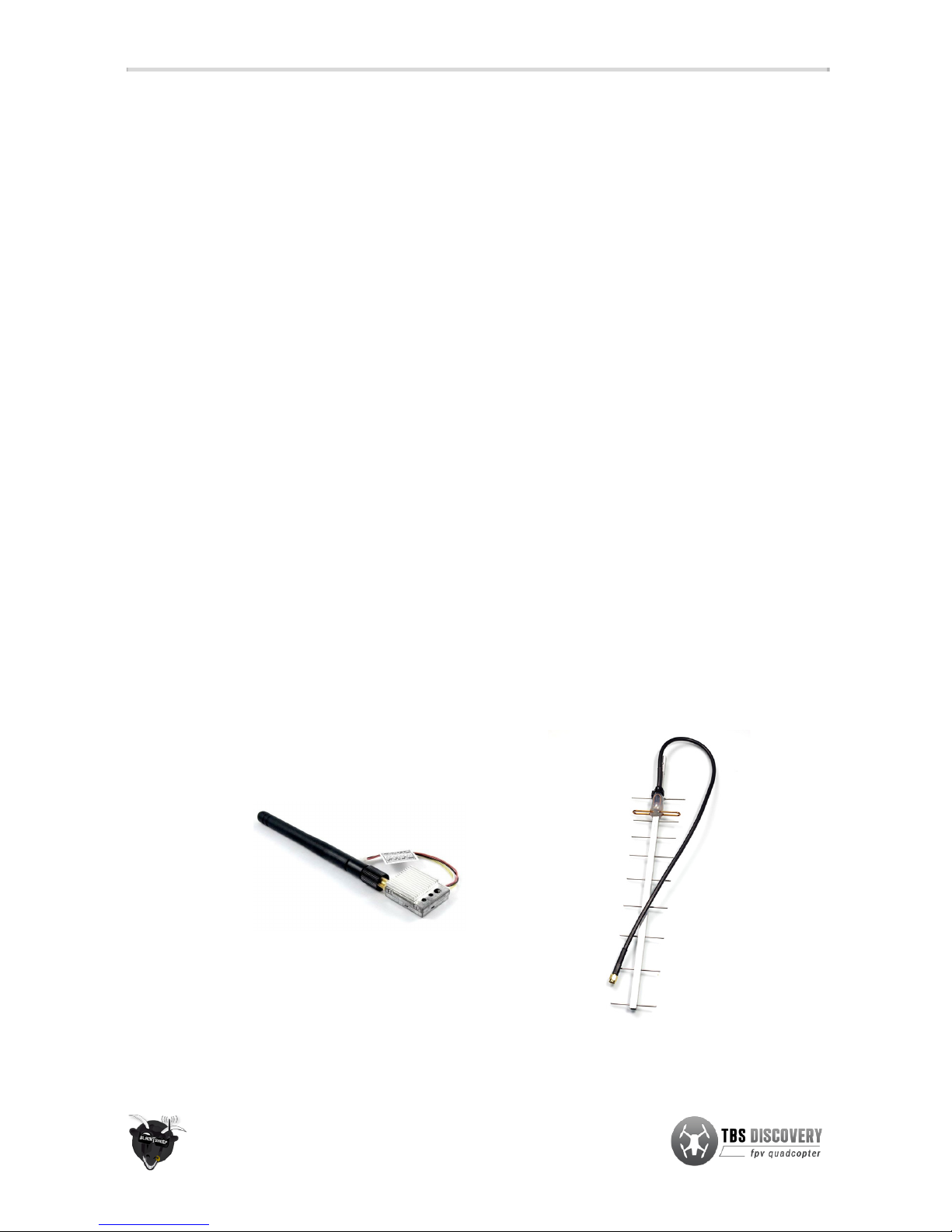
Frequency choice
Frequency choice depends on the ranges you want to fly. Using 5.8GHz video is an ideal frequency if you do not
plan on flying far away from yourself or behind objects. It is compatible with 2.4GHz remote controls.
Using 2.4GHz video (TBS video frequency of choice) will give you nearly unlimited range and far superior link
quality, but you can not use your 2.4GHz remote control on the same quad because of limited separation (it is no
problem for our R/C buddies to fly with 2.4GHz remote controls next to you though!). You will need an EzUHF or
any other UHF control system available on the market.
1.2GHz works very well in urban environments where the 2.4GHz band is completely polluted.
By using the same connector type across all transmission frequencies, the TBS eco-system allows quick and
effortless switching between the frequencies.
Typical ranges (based on customer feedback) with omnidirectional antennas:
●Lawmate 2.4GHz 500mW - 4km
●TBS 5.8GHz 25mW - 400m
●TBS 5.8GHz 200mW - 1.4km
●Boscam/Foxtech/HobbyKing 5.8GHz 500mW - do NOT buy, bad design!
●Boscam/Foxtech/HobbyKing 5.8GHz 400mW - 2.5km
●ImmersionRC 5.8GHz 600mW - 2.5km
More range can be achieved by using higher gain (directional) antennas. With the 11dBi TBS Yagi on 500mW
Lawmate 2.4GHz gear, 10km of range is no problem at all. The battery normally only lasts for 8km of flight (4km
and return.)
6

Choosing the right setup
If you are just getting into the hobby and you have absolutely nothing, consider the following components to
buy. Use these suggested setups as a “shopping list” if you are just getting started. Any existing gear you
already own (e.g. remote controls, chargers, batteries) can be used with the TBS DISCOVERY.
These setups, with the exception of the Camera Tripod and the Remote Control, are available from Team
BlackSheep. Remote controls can be purchased at your local hobby shop, camera tripods are available from big
electronics wholesalers or Ebay.
TBS DISCOVERY setup for short range flights
●Expected flight time: 8-12 min
●Approximate cost: US$ 1’600 - US$ 2’000
●Experience level: Beginner to Expert
●Ideal for: Parks, R/C clubs, front lawns
R/C transmitter/receiver:
Graupner MX-12 2.4GHz radio with bundled receiver (GR-6)
or Futaba 8FG / 7C 2.4GHz radio with included receiver (R6208SB / R617FS)
Quadrotor equipment:
4x DJI Flame Wheel F450 arms
4x TBS BULLETPROOF 30A 5V SBEC speed controllers
4x TBS 750kV brushless motors
4x Graupner E-Prop 10x5-inch propellers
1x DJI NAZA-M flight controller (optional GPS add-on)
Battery:
TBS 4S (14.8V) 3300mAh - 4500mAh 35C Lipo pack
Battery charger:
Graupner Ultramat 14S (premium) or TBS B6AC 80W (budget)
FPV transmitter:
TBS ROOKIE BOSCAM 5.8GHz 200mW video transmitter
FPV receiver:
TBS RC508 5.8GHz video receiver or Dominator 5.8GHz module
FPV pilot camera:
TBS 59 or TBS 69 FPV camera
FPV goggles:
FatShark Dominator video glasses
HD camera:
GoPro HD Hero 3 Black edition
Ground station
accessories:
TBS 3S 5000mAh Ground Station Lipo
Camera Tripod to mount your gear (e.g. Cullmann Primax 150)
7

TBS DISCOVERY setup for long range flights
●Expected flight time: 8-12 min
●Cost range: US$ 2’000 - US$ 2’800
●Experience level: Expert
●Ideal for: Long, wide open fields, plains, coastlines and valleys or urban flying
R/C transmitter/receiver:
Futaba 8FG / 7C or Graupner MX-12 radio
+ EzUHF 433MHz transmitter module and SRH-771 UHF antenna
+ EzUHF Lite 8-channel 433MHz receiver
Quadrotor equipment:
4x DJI Flame Wheel F450 arms
4x TBS BULLETPROOF 30A 5V SBEC speed controllers
4x TBS 900kV brushless motors
4x Graupner E-Prop 9x5-inch propellers
1x DJI NAZA-M flight controller (optional GPS add-on)
Battery:
TBS 4S (14.8V) 4500mAh 35C Lipo pack
Battery charger:
Graupner Ultramat 14S (premium) or TBS B6AC 80W (budget)
FPV transmitter:
Lawmate 2.4GHz 500mW Video Tx (stock or tuned)
FPV receiver:
Lawmate 2.4GHz Video Rx (stock or tuned) with 11dBi Yagi
FPV pilot camera:
TBS 59 or TBS 69 FPV camera
FPV goggles:
FatShark Dominator video glasses
HD camera:
GoPro HD Hero 3 Black edition
Ground station
accessories:
TBS 3S 5000mAh Ground Station Lipo
Camera Tripod to mount your gear (e.g. Cullmann Primax 150)
8
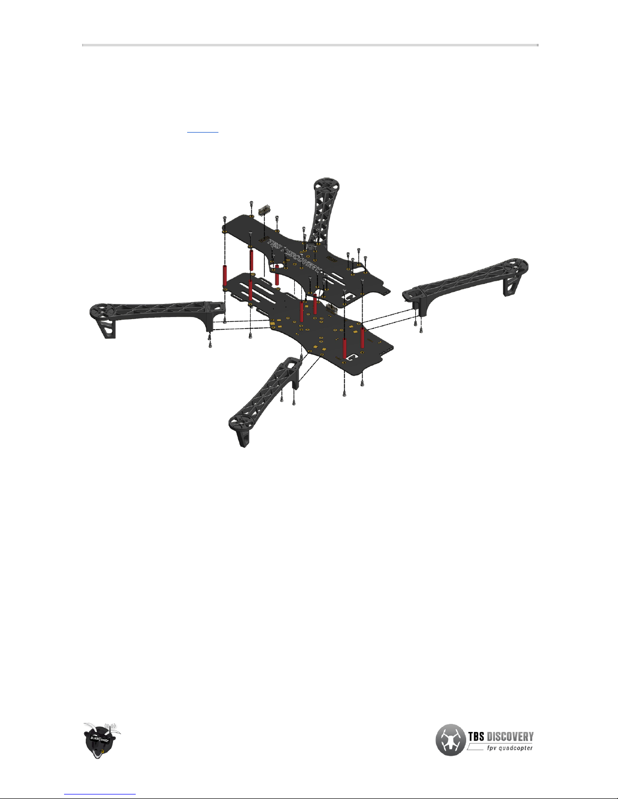
Frame assembly
Begin by assembling the base of the frame and soldering the speed controller, battery lead and flight controller
to the bottom power distribution board (PDB). In addition to the following assembly instructions, we have a
professionally produced “How To”-video on our website showing the assembly and electronics installation.
A more detailed image of the frame assembly is available as an appendix to this document.
Bottom plate
Power distribution
●Start by cutting the power pigtail to 12cm and pre-tinning (add solder to) the battery pads, speed
controller pads, auxiliary power pads (for flight controller power), speed controller power leads and
the battery pigtail. If needed, desolder and change the XT60 connector to your preferred connector of
choice.
●Solder the battery pigtail to the positive (red) and negative (black) pads located on the back-right side.
Do the same for the speed controllers; solder the speed controller power leads to the positive and
negative square pads located next to the four frame arm screw holes on both sides. Heat the solder
pad, hold the cable in a slight angle (so both cables will form a “V”), remove the solder iron and keep
still for the solder to settle nicely.
●Pick one of the available auxiliary power pads (smaller squares) and solder the flight controller power
unit and/or voltage regulator(s) to the frame. We recommend the pads on the middle-left side.
9

1
1
2
2
3
3
4
4
5
5
6
6
7
7
8
8
A A
B B
C C
D D
E E
F F
SHEET 1 OF 1
DRAWN
CHECKED
QA
MFG
APPROVED
TBS Associates Inc 31.07.2013
DWG NO
tbs_discovery_pro_frame
TITLE
SIZE
A2
SCALE
REV
Table of contents
Other tbs electronics Drone manuals


 user manual")


