tbs electronics powersine 200-12 User manual

Printed in The Netherlands
Owner’s manual
Gebruiksaanwijzing
Bedienerhandbuch
Mode d'emploi
powersine
powersinepowersine
powersine 200-12
powersine
powersinepowersine
powersine 200-24
powersine
powersinepowersine
powersine 200-48
powersine
powersinepowersine
powersine 300-12
powersine
powersinepowersine
powersine 350-24
powersine
powersinepowersine
powersine 450-48
powersine
powersinepowersine
powersine 600-12
powersine
powersinepowersine
powersine 800-24
powersine
powersinepowersine
powersine 800-48
Designed and manufactured in The Netherlands by :
TBS Electronics BV
De Marowijne 3
1689 AR Zwaag
www.tbs-electronics.com

Powersine dc to ac sinewave inverters
Powersine dc to ac sinewave invertersPowersine dc to ac sinewave inverters
Powersine dc to ac sinewave inverters
- 1 -
Owner’s manual
Gebruiksaanwijzing
Bedienerhandbuch
Mode d'emploi
powersine
powersinepowersine
powersine 200-12
powersine
powersinepowersine
powersine 200-24
powersine
powersinepowersine
powersine 200-48
powersine
powersinepowersine
powersine 300-12
powersine
powersinepowersine
powersine 350-24
powersine
powersinepowersine
powersine 450-48
powersine
powersinepowersine
powersine 600-12
powersine
powersinepowersine
powersine 800-24
powersine
powersinepowersine
powersine 800-48
Designed and manufactured in The Netherlands by :
TBS Electronics BV
De Marowijne 3
1689 AR Zwaag
www.tbs-electronics.com
COPYRIGHT © 2004-2010 (rev4endf)

Powersine dc to ac sinewave inverters
Powersine dc to ac sinewave invertersPowersine dc to ac sinewave inverters
Powersine dc to ac sinewave inverters
- 2 -
English Page 3
Nederlands Pagina 17
Deutsch Seite 30
Francais Page 44

Powersine dc to ac sinewave inverters
Powersine dc to ac sinewave invertersPowersine dc to ac sinewave inverters
Powersine dc to ac sinewave inverters
- 3 -
TABLE OF CONTENTS
1. INTRODUCTION. . . . . . . . . . . . . . . . . . . . . . . . 4
2. INSTALLATION . . . . . . . . . . . . . . . . . . . . . . . . 4
2.1 Placement of the inverter . . . . . . . . . . . . . . . . . . . 4
2.2 The “Remote on/off” function (PS600-12 up to PS800-48 models only) . . . 5
2.3 Battery requirements . . . . . . . . . . . . . . . . . . . . 6
2.4 Connection to the battery . . . . . . . . . . . . . . . . . . . 6
2.4.1 General precautions about working with batteries . . . . . . . . . . 6
2.5 Connecting the load. . . . . . . . . . . . . . . . . . . . . 8
2.6 Activating the inverter . . . . . . . . . . . . . . . . . . . . 8
3. TROUBLESHOOTING . . . . . . . . . . . . . . . . . . . . . . 9
3.1 The flash sequence table . . . . . . . . . . . . . . . . . . . 9
3.2 Acoustical messages (except PS200-xx models) . . . . . . . . . . . 10
3.3 Troubleshooting guideline. . . . . . . . . . . . . . . . . . . 10
4. WARRANTY / LIMITS OF RESPONSIBILITY . . . . . . . . . . . . . . 12
5. TECHNICAL DATA . . . . . . . . . . . . . . . . . . . . . . . 13
5.1 Powersine 200-12, 200-24 and 200-48 . . . . . . . . . . . . . . 13
5.2 Powersine 300-12, 350-24 and 450-48 . . . . . . . . . . . . . . 14
5.3 Powersine 600-12, 800-24 and 800-48 . . . . . . . . . . . . . . 14
6. DECLARATION OF CONFORMITY . . . . . . . . . . . . . . . . . 16
Powersine dc to ac sinewave inverters
Powersine dc to ac sinewave invertersPowersine dc to ac sinewave inverters
Powersine dc to ac sinewave inverters
- 4 -
1. INTRODUCTION
Thank you for choosing a Powersine DC to AC inverter as your power source. The
Powersine inverter series are one of the most sophisticated inverters available today. With
high reliability, efficiency and sine quality as our most important design goals, the Powersine
inverter series is developed to serve you with safe and trouble free operation for years.
Your Powersine inverter features an advanced micro processor control system with a
MOSFET power stage and a low loss toroidal transformer. This toroidal transformer in
combination with well over dimensioned power components, ensures a very reliable
operation, so that extreme overload conditions, like startup of compressors or pumps, can be
handled safely.
To get optimal feedback from your inverter while operating, a build in diagnosis system will
warn you optically by different flash sequences, depending on the error situation. See the
troubleshooting chapter for the flash sequence table. Also, the inverter will warn you
acoustically before it’s going to shut down in a low battery, overload or high temperature
condition (except PS200-xx models).
To get optimal performance and safe operation from your inverter, it must be installed and
used properly. Please read this manual very carefully, especially the warning and caution
statements, before installing and using your Powersine inverter.
2. INSTALLATION
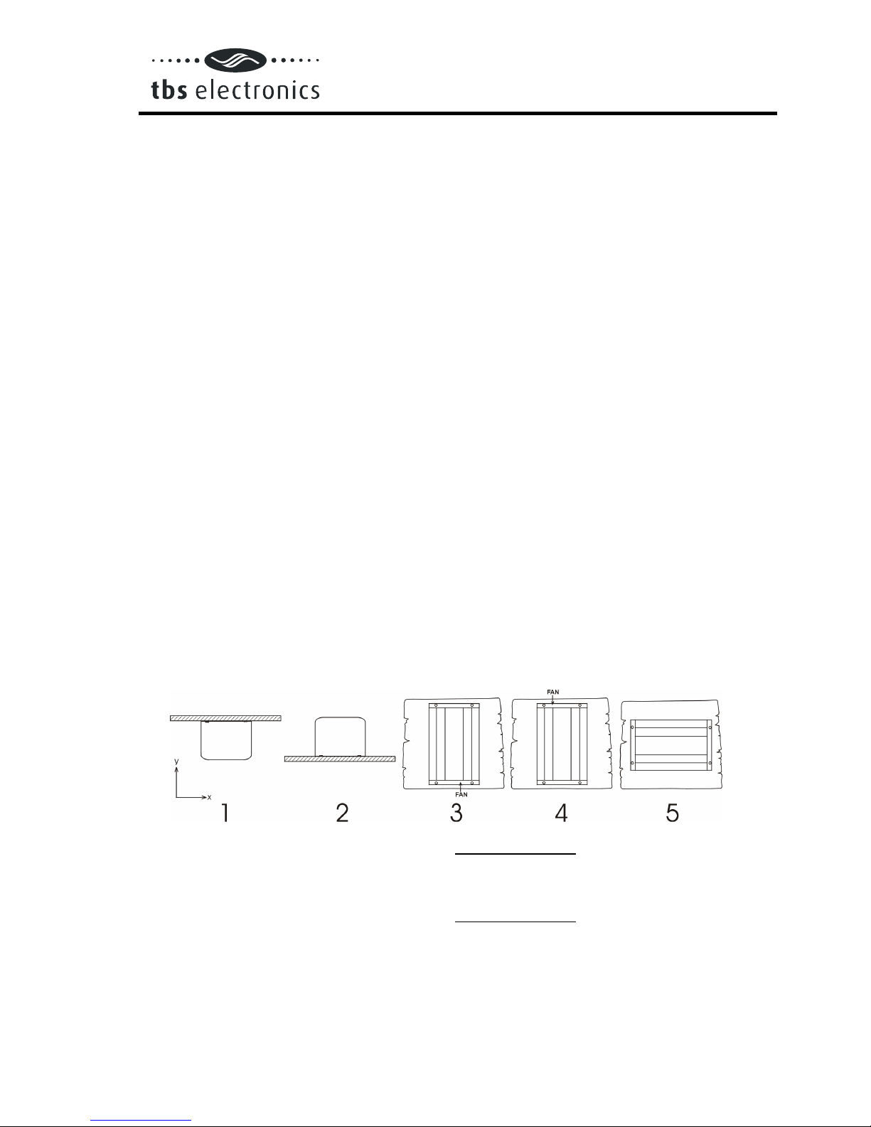
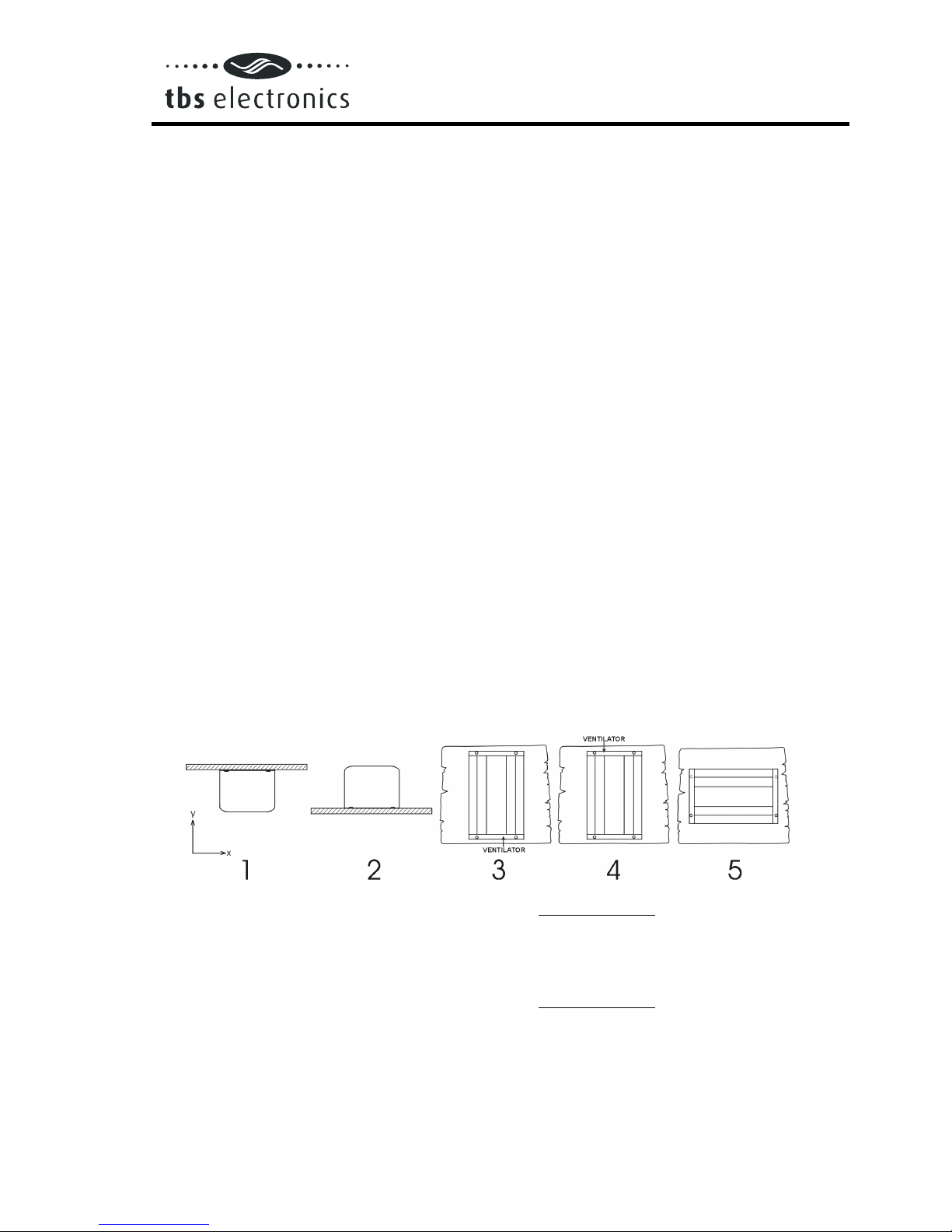
2.1 Placement of the inverter
1. Ceiling mounting : Not recommended
2. Floor mounting : OK
3. Vertical wall mounting, fan at bottom : OK (beware of small objects falling through
the ventilation openings on top)
4. Vertical wall mounting, fan on top : Not recommended
5. Horizontal wall mounting : OK
For best operating results, the inverter should be placed on a flat surface. To ensure a
trouble free operation of the inverter, it must be used in locations that meet the following
requirements :
a. Avoid any contact with water on the inverter. Do not expose the inverter to rain or

Powersine dc to ac sinewave inverters
Powersine dc to ac sinewave invertersPowersine dc to ac sinewave inverters
Powersine dc to ac sinewave inverters
- 5 -
moisture.
b. Do not place the unit in direct sunlight or other high temperature environments.
Ambient air temperature should be between 0 °C and 40 °C (humidity < 95% non
condensing). Note that in some extreme situations the inverter’s case temperature can
exceed 70 °C.
c. Do not obstruct the airflow around the inverter. Leave at least 10 centimeters clearance
around the inverter. Do not place items on or over the inverter while it’s operating.
When the inverter is running to hot, it will shut down until a safe temperature level is
reached to restart the inverter.
d. Never use the inverter at locations where there is gas or explosion danger, like for
example directly on top of batteries.
e. Do not expose the inverter to dusty environments
2.2 The “Remote on/off” function (PS600-12 up to PS800-48 models only)
The Powersine 600-12 up to 800-48 models are equipped with “Remote on/off”
terminals for connection to an external on/off switch. The two wires of the external switch
must be connected to these terminals as indicated below. The slide switch on the
frontpanel must be moved to the right (factory setting is left) when operating the unit by a
remote switch as shown below :
max. 50 meters
remote spst
switch
control by remote switch
control by local switch
The local on/off switch on the frontpanel always overrides the remote switch. So in order
to use the remote switch, the local on/off switch must be in the ‘on’ or ‘auto standby’
(ASB) position.
CAUTION
MAKE SURE THAT WHEN INSTALLING THE REMOTE SWITCH, THE
BATTERY IS NOT CONNECTED YET.

Powersine dc to ac sinewave inverters
Powersine dc to ac sinewave invertersPowersine dc to ac sinewave inverters
Powersine dc to ac sinewave inverters
- 6 -
2.3 Battery requirements
For correct operation, the battery voltage should be between 0.92xVnom and 1.23xVnom
where Vnom is 12V, 24V or 48V depending on model, and must be able to supply
sufficient current to your inverter. The following table displays the recommended battery
capacity per inverter type :
Inverter type : Iin at Pnom :
Recommended battery cap. :
PS200-12 18 ADC ≥50 Ah
PS200-24 9 ADC ≥30 Ah
PS200-48 4 ADC ≥20 Ah
PS300-12 26 ADC ≥100 Ah
PS350-24 15 ADC ≥60 Ah
PS450-48 7 ADC ≥30 Ah
PS600-12 47 ADC ≥200Ah
PS800-24 29 ADC ≥120Ah
PS800-48 14 ADC ≥60Ah
For short time inverter usage the recommended battery capacity can be halved. The inverter shuts down when
the battery voltage is below approx. 0.88xVnom or above 1.3xVnom. In a low or high battery situation the
inverter is generating one beep per second to inform you about a possible inverter shut down (except PS200-
xx models). This acoustical message will start at a battery voltage which is close to the shutdown voltage.
CAUTION
ALL 12V INVERTERS MUST BE CONNECTED ONLY TO A 12V
BATTERY.
The inverter will not operate from a 6V battery and will be damaged when
connected to battery voltages higher than 24V.
ALL 24V INVERTERS MUST BE CONNECTED ONLY TO A 24V
BATTERY.
The inverter will not operate from a 12V battery and may be damaged
when connected to battery voltages higher than 31V.
ALL 48V INVERTERS MUST BE CONNECTED ONLY TO A 48V
BATTERY.
The inverter will not operate from a < 40V battery and may be damaged
when connected to battery voltages higher than 60V.
2.4 Connection to the battery
Unless it is absolutely necessary, TBS advises not to extend the battery wires. Extending
the battery wires may increase system losses and can cause inverter malfunctioning. If it
is unavoidable to extend these wires, use a wire gauge of at least 1.5 times larger than
the ones supplied with the inverter. Maximum recommended battery wire length is approx.
3 meters.
2.4.1 General precautions about working with batteries
1. Working in vicinity of a lead acid battery is dangerous. Batteries can generate
explosive gases during operation. Never smoke or allow a spark or flame in vicinity
of a battery. Provide sufficient ventilation around the battery.
2. Wear eye and clothing protection. Avoid touching eyes while working near batteries.

Powersine dc to ac sinewave inverters
Powersine dc to ac sinewave invertersPowersine dc to ac sinewave inverters
Powersine dc to ac sinewave inverters
- 7 -
Wash your hands when done.
3. If battery acid contacts skin or clothing, wash immediately with soap and water. If
acid enters eye, immediately flood eye with running cold water for at least 15
minutes and get medical attention immediately.
4. Be careful when using metal tools in vicinity of batteries. Dropping a metal tool onto
a battery might cause a shorted battery and an explosion.
5. Remove personal metal items such as rings, bracelets, necklaces, and watches
when working with a battery. A battery can produce a short-circuit current high
enough to weld a ring or the like to metal, causing severe burns.
CAUTION
THE RED WIRE MUST BE CONNECTED TO THE POSITIVE (+)
TERMINAL AND THE BLACK WIRE TO THE NEGATIVE (-)
TERMINAL OF THE BATTERY.
Reverse polarity connection of the battery wires can damage the
inverter! Damage caused by reversed polarity is not covered by the
warranty. Make sure the powerswitch is in the OFF ‘0’ position before
connecting the battery.
Powersine dc to ac sinewave inverters
Powersine dc to ac sinewave invertersPowersine dc to ac sinewave inverters
Powersine dc to ac sinewave inverters
- 8 -
2.5 Connecting the load
Before you connect your appliance(s) to the inverter, always check it’s maximum power
consumption. Do not connect appliances to the inverter needing more than the nominal
power rating of the inverter continuously. Some appliances like motors or pumps, are
drawing large inrush currents in a startup situation. In these situations, it is possible that
the startup current exceeds the overcurrent trip level of the inverter. In this case the output
voltage will shortly decrease to limit the output current of the inverter. If this overcurrent
trip level is continuously exceeded, the inverter will shut down and restart within 18
seconds. In this case it is advisable to disconnect this appliance from the inverter, since it
requires to much power to be driven by this inverter. Note that at higher ambient
temperature levels, the overload capacity of the inverter is reduced.
WARNING
WHEN CONNECTING MORE THAN ONE APPLIANCE TO THE
INVERTER, IN COMBINATION WITH A COMPUTER, NOTE THAT IF
ONE OF THE APPLIANCES IS STARTING UP, IT CAN CAUSE YOUR
COMPUTER TO REBOOT DUE TO A SUDDEN VOLTAGE DROP.
CAUTION
NEVER CONNECT THE INVERTER’S OUTPUT TO THE AC
DISTRIBUTION GRID, LIKE YOUR HOUSEHOLD AC WALL OUTLET.
IT WILL PERMANENTLY DAMAGE THE INVERTER!
2.6 Activating the inverter
When all the above requirements are checked and satisfied and all connections are made,
it’s time to turn on your Powersine inverter by pushing the powerswitch in the ‘I’ position
(see top label for pushdirection). After a short two tone beep (except PS200-xx models),
indicating that all internal circuits are checked, the sinewave shaped output voltage is
gently rising until 230V/50Hz ±2% (or 115V/60Hz ±3%) is reached.
When the inverter is not supplying power to an appliance for a longer time, it’s
recommended to use the inverter in the "Auto Standby" (ASB) mode to heavily reduce the
inverter's own power consumption. In this case the power switch must be pushed in the
'II' position. In the ASB mode the inverter will generate a testpulse on it's output once per
second, to check if there is a load applied. When the ASB mode is activated (by
generating a reversed two tone beep, (except PS200-xx models), the indicator LED will
be continuously on for 4 seconds while the inverter outputs a continuous 230V (or 115V)
sinewave. After this 4 seconds the continuous output will change to a pulsed output,
indicated by a flashing indicator LED. When a load is connected to the inverter output (or
switched on) drawing more than approx. 5W, 12W or 15W (depending on model), the
inverter jumps to the continuous mode immediately, delivering power to the load. When

Powersine dc to ac sinewave inverters
Powersine dc to ac sinewave invertersPowersine dc to ac sinewave inverters
Powersine dc to ac sinewave inverters
- 9 -
the load is disconnected again (or switched off), the indicator LED starts flashing again
after 4 seconds, and the inverter jumps back to the pulsed output ASB mode. This way
the inverter automatically jumps to a low power 'sleep' mode when there is no power
demand on the output.
Note that some loads like TV/video equipment (with standby mode) and alarm clocks
need continuous power so that the ASB mode can not be used. With some small non
compensated loads, it is possible that the inverter jumps from continuous output to pulsed
output and vice versa all the time. In this case you have to connect a small additional load
to the AC output.
WARNING
IF THE INVERTER JUMPED INTO AN ‘ERROR MODE’ (SEE
CHAPTER 3.1) DUE TO AN OVERLOAD OR SHORT CIRCUIT, THE
INVERTER WILL AUTOMATICALLY RESTART AFTER ABOUT 18
SECONDS.
In case of an overtemperature error, the inverter will automatically restart
after it has reached an acceptable temperature. Right before the inverter
will restart, it will warn you with a short two-tone beep (except PS200-xx
models).
NEVER SERVICE THE AC CONNECTIONS WHEN THE INVERTER IS
STILL RUNNING IN AN ERROR MODE!
WARNING
THE BUILD IN LARGE ELECTROLYTIC CAPACITORS CAN HOLD
SIGNIFICANT DC VOLTAGE WHEN THE BATTERIES ARE
DISCONNECTED.
To avoid sparks or short inverter operation, it is advisable to switch on
the inverter for 10 seconds after battery disconnection, before you
transport the inverter.
3. TROUBLESHOOTING
3.1 The flash sequence table
Your Powersine inverter is equipped with a self diagnosis system, to inform you about the
cause of inverter shut down. To make this visible the red error/power LED on the
frontpanel of the inverter, can flash in four different sequences. The duration, or
timeperiod, of this sequence is about 1 second. During this timeperiod the red LED can
flash four times in a row at most. The number of flashes in this time period indicates the
cause of inverter shut down.

Powersine dc to ac sinewave inverters
Powersine dc to ac sinewave invertersPowersine dc to ac sinewave inverters
Powersine dc to ac sinewave inverters
- 10 -
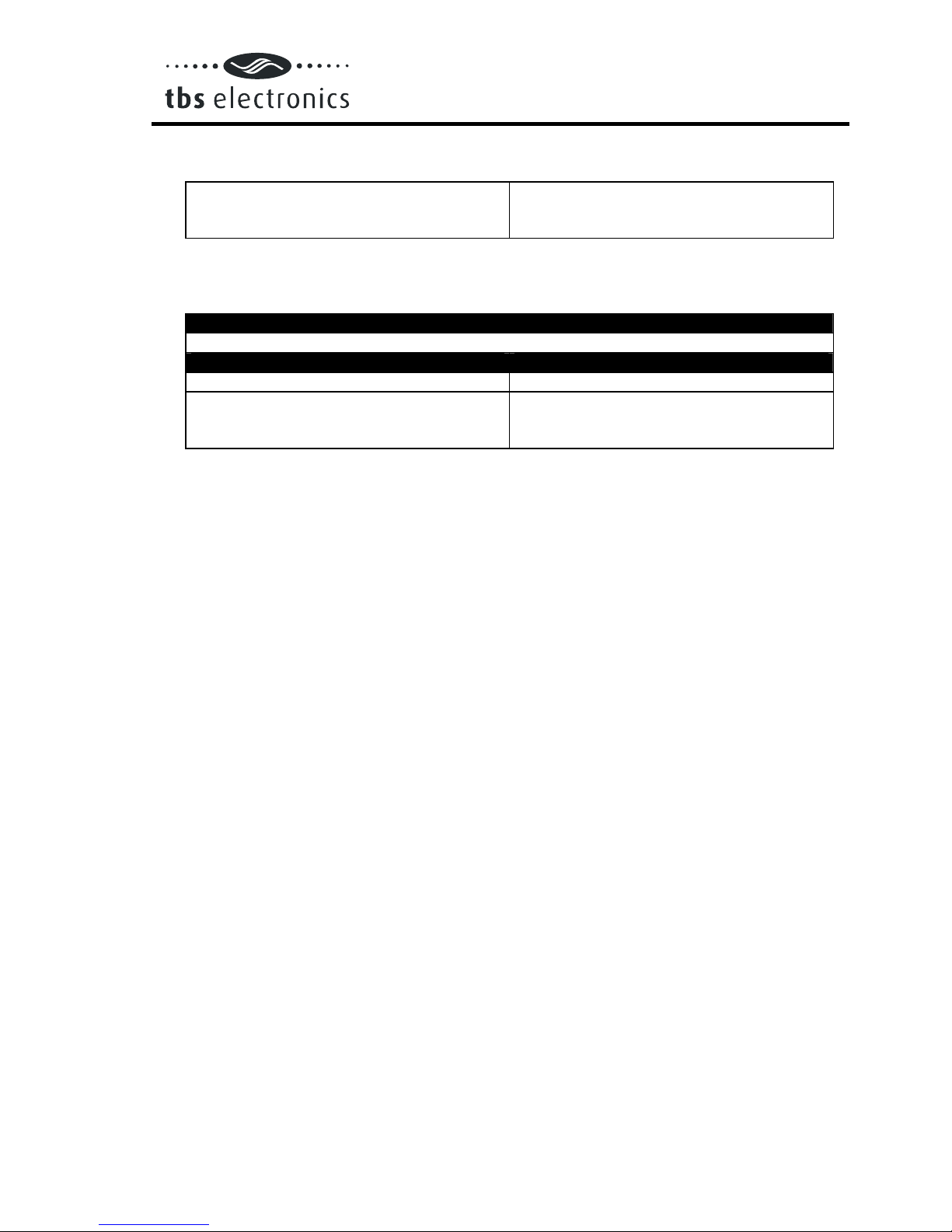
In the next table you can find out what kind of flash sequence belongs to which error.
Red LED conditions :
= LED flashing
= LED ON
= LED OFF
Time period (1 second) Type of error
Battery voltage too low, too high (one flash
per second)
Overloaded or shorted output
(two flashes per second)
Inverter temperature too high. Cooling down
(three flashes per second)
Inverter in ASB mode
(four flashes per second)
→Power ON, inverter in normal operation
→Inverter OFF
3.2 Acoustical messages (except PS200-xx models)
To warn you before the inverter might shut down, the inverter is equipped with an
acoustical alarm. There are three kinds of acoustical messages depending on the cause
of possible inverter shutdown. These messages are related to the red LED blinking
sequences mentioned previously.
Message 1: One beep per second. The battery voltage has reached a too low or too
high level. If the battery voltage respectively decreases or increases any
further, the inverter shuts down.
Message 2: Two beeps per second. The inverter will shut down soon due to an
overloaded output. Note that at heavy overloads the alarm will not sound
due to too fast inverter shut down.
Message 3: Three beeps per second. The inverter will shut down when it’s
temperature is rising another three degrees Celsius.
3.3 Troubleshooting guideline
PROBLEM : Inverter is not working (red LED OFF)
Possible cause : Remedy :
Power switch in OFF (0) position Push the power switch in the ON (1)
position.
Poor contact between the inverter’s battery
wires and the battery terminals. Clean battery terminals or inverter wire
contacts. Tighten battery terminal screws.
Blown inverter fuse The inverter has to be returned for service.
Very poor battery condition Replace battery

Powersine dc to ac sinewave inverters
Powersine dc to ac sinewave invertersPowersine dc to ac sinewave inverters
Powersine dc to ac sinewave inverters
- 11 -
PROBLEM : ‘Battery voltage too low or too high’ error keeps on appearing
Possible cause : Remedy :
Poor battery condition Replace battery or charge it first
Poor connection or inadequate wiring
between battery and inverter, resulting in
too much voltage drop
When extending the battery wires of the
inverter make sure you use the correct wire
gauge (≥1.5 times larger than the fixed
battery wires). It’s not advisable to extend
the battery wires to more than 3 meters.
General failure in your electrical system (in
case of no direct battery connection) Check your electrical system or consult an
electrical engineer to check it for you
PROBLEM : ‘Overloaded or shorted output’ error keeps on appearing
Possible cause : Remedy :
Inverter is overloaded Make sure that the total power rating of the
connected equipment is lower than the
nominal inverter power rating.
Connected equipment features a bad power
factor (cosϕat sinusoidal currents)
reduce the required power consumption of
the load. Please note that for example most
computer loads feature a bad power factor,
which causes a reduction of the maximum
output power of the inverter by approx.
20%.
Connected equipment causes a short circuit
at the inverter’s output Make sure that the connected equipment is
not broken or malfunctioning. Check if the
AC power cord between the inverter and
the connected equipment is ok. Any
physical damage on the power cord can
produce a short circuit. Be careful in these
kind of situations!
Connected equipment produces a too large
inrush current Try to power-up connected equipment
successively, and not simultaneously. Or
connect the load first and then turn-on the
inverter. Otherwise stop using the
connected load, it’s not suitable to drive it
with this inverter
PROBLEM : ‘Inverter temperature too high. Cooling down’ error keeps on
appearing
Possible cause : Remedy :
Airflow around the inverter is obstructed Make sure there is at least 10 centimeters
of clearance around the inverter. Remove
any items placed on or over the inverter.
Keep the inverter away from direct sunlight
or heat producing equipment
Powersine dc to ac sinewave inverters
Powersine dc to ac sinewave invertersPowersine dc to ac sinewave inverters
Powersine dc to ac sinewave inverters
- 12 -
Too high ambient temperature Move the inverter to a cooler place or
provide additional cooling by an external
fan
Note : Don’t turn off the inverter when it’s operating in an ‘Inverter temperature too high.
Cooling down’ error. The inverter needs this error time to cool down.
PROBLEM : Inverter jumps between continuous mode and ASB mode all the time
Possible cause : Remedy :
Connected load is not compensated or the
ratio between inrush current and continuous
current is too large.
Connect an additional load to the output.
If none of the above remedies will help solving the problem you encounter, it’s best to
contact your local TBS distributor for further help and/or possible repair of your inverter.
Do not open the inverter yourself, there are dangerous high voltages present inside.
Opening the inverter will directly void your warranty.
4. WARRANTY / LIMITS OF RESPONSIBILITY
TBS Electronics (TBS) warrants this inverter to be free from defects in workmanship or
materials for 24 months from the date of purchase. During this period TBS will repair the
defective inverter free of charge. TBS is not responsible for any costs of the transport of
this inverter.
This warranty is void if the inverter has suffered any physical damage or alteration, either
internally or externally, and does not cover damage arising from improper use
1)
,
attempting to operate the inverter with excessive power consumption requirements, or
from use in an unsuitable environment.
This warranty will not apply where the product has been misused, neglected, improperly
installed or repaired by anyone other than TBS. TBS is not responsible for any loss,
damage or costs arising from improper use, use in an unsuitable environment, improper
installing of the inverter and inverter malfunctioning.
Since TBS cannot control the use and installation (according to local regulations) of their
products, the customer is always responsible for the actual use of these products. TBS
products are not designed for use as cricital components in life support devices or
systems, that can potentially harm humans and/or the environment. The customer is
always responsible when implementing TBS products in these kind of applications. TBS
does not accept any responsibility for any violation of patents or other rights of third
parties, resulting from the use of the TBS product. TBS keeps the right to change product
specifications without previous notice.
1)
Examples of improper use are :
- Too high input voltage applied
- Reverse connection of battery polarity
- Mechanical stressed enclosure or internals due to harsh handling and/or incorrect
packaging
Powersine dc to ac sinewave inverters
Powersine dc to ac sinewave invertersPowersine dc to ac sinewave inverters
Powersine dc to ac sinewave inverters
- 13 -
- Backfeed via inverter output from external power source like public grid or generator
- contact with any liquids or oxidation caused by condensation
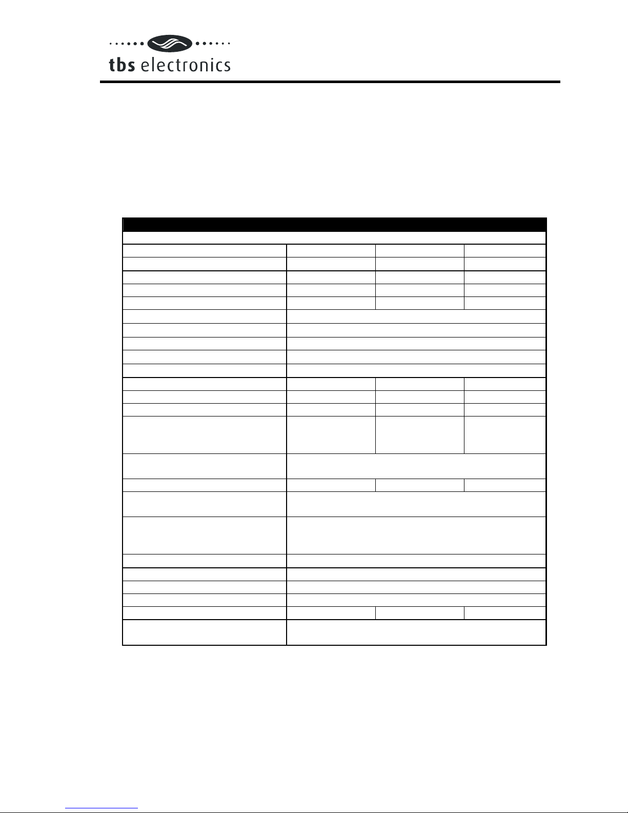
5. TECHNICAL DATA
5.1 Powersine 200-12, 200-24 and 200-48
TECHNICAL DATA
PS200-12 PS200-24 PS200-48
Output power
1)
: @ Ta = 25°C
Pnom 175VA 175VA 175VA
P10minutes 210VA 220VA 220VA
Psurge 400VA 500VA 500VA
Output voltage 230Vac ±2% or 115Vac ±2%
Output frequency 50Hz ±0.05% or 60Hz ±0.05%
Output waveform True sinewave (THD < 5%
1)
@ Pnom)
Permissible cos ϕof load 0.2 – 1 (up to Pnom)
Input voltage (±3% tolerance) :
Nominal 12Vdc 24Vdc 48Vdc
Range 10.5
2)
– 16Vdc 21
2)
– 31Vdc 41
2)
– 60Vdc
Maximum efficiency 90% 91% 93%
No load power consumption at
nominal input voltage
[ASB]
< 2.8W
[0.6W] < 3W
[0.8W] < 4W
[1.2W]
Operating temperature range
(ambient) -20°C to +50 °C
ASB threshold Pout = 12W Pout = 15W Pout = 15W
Protections against Short circuit, overload, high temperature and low
battery voltage
Indications (by pre-programmed
flashing sequences of the power
LED)
Power on, short circuit/overload, high temperature,
high/low battery voltage and ASB mode
DC input connection Two wires, length 1.5 meters, ∅4mm²
AC output connection IEC-320 AC outlet
Enclosure body size (l x h x w) 154 x 98 x 130mm (without mounting brackets)
Protection class IP20
Total weight 2.4 kg 2.4 kg 2.4 kg
The inverter complies with the
following standards : See page 16

Powersine dc to ac sinewave inverters
Powersine dc to ac sinewave invertersPowersine dc to ac sinewave inverters
Powersine dc to ac sinewave inverters
- 14 -
5.2 Powersine 300-12, 350-24 and 450-48
TECHNICAL DATA
PS300-12 PS350-24 PS450-48
Output power
1)
: @ Ta = 25°C
Pnom 250VA 300VA 300VA
P10minutes 330VA 360VA 450VA
Psurge 700VA 800VA 800VA
Output voltage 230Vac ±2% or 115vac ±2%
Output frequency 50Hz ±0.05% or 60Hz ±0.05%
Output waveform True sinewave (THD < 5%
1)
@ Pnom)
Permissible cos ϕof load 0.2 – 1 (up to Pnom)
Input voltage (±3% tolerance) :
Nominal 12Vdc 24Vdc 48Vdc
Range 10.5
2)
– 16Vdc 21
2)
– 31Vdc 41
2)
– 60Vdc
Maximum efficiency 91% 93% 95%
No load power consumption at
nominal input voltage
[ASB]
< 3W
[0.7W] < 3.5W
[0.8W] < 6.5W
[1.3W]
Operating temperature range
(ambient) -20°C to +50 °C
ASB threshold Pout = 12W Pout = 15W Pout = 15W
Protections against Short circuit, overload, high temperature and low
battery voltage
Indications (by pre-programmed
flashing sequences of the power
LED)
Power on, short circuit/overload, high temperature,
high/low battery voltage and ASB mode
DC input connection Two wires, length 1.5 meters, ∅4mm²
AC output connection IEC-320 AC outlet
Enclosure body size (l x h x w) 184 x 98 x 130mm (without mounting brackets)
Protection class IP20
Total weight 3.5 kg 3.5 kg 3.5 kg
The inverter complies with the
following standards : See page 16
5.3 Powersine 600-12, 800-24 and 800-48
TECHNICAL DATA
PS600-12 PS800-24 PS800-48
Output power
1)
: @ Ta = 25°C
Pnom 500VA 600VA 600VA
P10minutes 600VA 800VA 800VA
Psurge 1000VA 1200VA 1250VA
Output voltage 230Vac ±2% or 115Vac ±2%
Output frequency 50Hz ±0.05% or 60Hz ±0.05%

Powersine dc to ac sinewave inverters
Powersine dc to ac sinewave invertersPowersine dc to ac sinewave inverters
Powersine dc to ac sinewave inverters
- 15 -
Output waveform True sinewave (THD < 5%
1)
@ Pnom)
Permissible cos ϕof load 0.2 – 1 (up to Pnom)
Input voltage (±3% tolerance) :
Nominal 12Vdc 24Vdc 48Vdc
Range 10.5
2)
– 16Vdc 21
2)
– 31Vdc 41
2)
– 60Vdc
Maximum efficiency 92% 93% 94%
No load power consumption at
nominal input voltage
[ASB]
< 4.8W
[0.4W] < 6.5W
[0.7W] < 8.2W
[0.5W]
Operating temperature range
(ambient) -20°C to +50 °C
ASB threshold Pout = 15W Pout = 15W Pout = 15W
Protections against Short circuit, overload, high temperature and low
battery voltage
Indications (by pre-programmed
flashing sequences of the power
LED)
Power on, short circuit/overload, high temperature,
high/low battery voltage and ASB mode
DC input connection Two wires, length 1.5 meters, ∅10mm²
AC output connection IEC-320 AC outlet
Enclosure body size (l x h x w) 228 x 113 x 163mm (without mounting brackets)
Protection class IP20
Total weight 6.2 kg 6.2 kg 6.2 kg
The inverter complies with the
following standards : See page 16
Note : the given specifications are subject to change without notice
1)
Measured with resistive load. Power ratings are subject to a tolerance of ±4% and are
decreasing as temperature rises with a rate of approx. 1.2%/°C starting from 25°C.
2)
Undervoltage limit is dynamic. This limit decreases with increasing load to compensate
the voltage drop across cables and connections.

Powersine dc to ac sinewave inverters
Powersine dc to ac sinewave invertersPowersine dc to ac sinewave inverters
Powersine dc to ac sinewave inverters
- 16 -
6. DECLARATION OF CONFORMITY
MANUFACTURER : TBS Electronics BV
ADDRESS : De Marowijne 3
1689AR Zwaag
The Netherlands
Declares that the following products :
PRODUCT TYPE : DC TO AC SINEWAVE INVERTER
MODELS : - Powersine 200-12
- Powersine 200-24
- Powersine 200-48
- Powersine 300-12
- Powersine 350-24
- Powersine 450-48
- Powersine 600-12
- Powersine 800-24
- Powersine 800-48
Conform to the requirements of the following Directives of the European Union :
EMC Directive 2004/108/EC
Automotive Directive 95/54/EC
RoHS Directive 2002/95/EC
The above products are in conformity with the following harmonized standards :
- EN61000-6-3 : 2001 EMC - Generic Emissions Standard
- EN61000-6-2 : 2005 EMC - Generic Immunity Standard
Low Voltage Directive (2006/95/EC) : EN60335-1 : 1999

Powersine dc to ac sinewave inverters
Powersine dc to ac sinewave invertersPowersine dc to ac sinewave inverters
Powersine dc to ac sinewave inverters
- 17 -
INHOUDSOPGAVE
1. INTRODUCTIE . . . . . . . . . . . . . . . . . . . . . . . . 18
2. INSTALLATIE . . . . . . . . . . . . . . . . . . . . . . . . . 18
2.1 Plaatsing van de omvormer . . . . . . . . . . . . . . . . . . 18
2.2 De “Remote on/off” functie (alleen PS600-12 tot en met PS800-48 modellen) . 19
2.3 Accu eisen . . . . . . . . . . . . . . . . . . . . . . . . 20
2.4 Het aansluiten van de accu . . . . . . . . . . . . . . . . . . 20
2.4.1 Voorzorgsmaatregelen omtrent het werken met accu’s . . . . . . . . 21
2.5 Aansluiten van de belasting . . . . . . . . . . . . . . . . . . 22
2.6 Activeren van de omvormer . . . . . . . . . . . . . . . . . . 22
3. HET OPLOSSEN VAN STORINGEN . . . . . . . . . . . . . . . . . 24
3.1 Optische alarmen . . . . . . . . . . . . . . . . . . . . . 24
3.2 Akoestische alarmen (behalve PS200-xx modellen) . . . . . . . . . . 24
3.3 Storingen met mogelijke oplossingen . . . . . . . . . . . . . . . 25
4. GARANTIE / AANSPRAKELIJKHEID FABRIKANT . . . . . . . . . . . . 26
5. TECHNISCHE GEGEVENS . . . . . . . . . . . . . . . . . . . . 27
5.1 Powersine 200-xx . . . . . . . . . . . . . . . . . . . . . 27
5.2 Powersine 300-12, 350-24 en 450-48 . . . . . . . . . . . . . . . 28
5.3 Powersine 600-12, 800-24 en 800-48 . . . . . . . . . . . . . . . 29
6. CONFORMITEITSVERKLARING . . . . . . . . . . . . . . . . . . 29
Powersine dc to ac sinewave inverters
Powersine dc to ac sinewave invertersPowersine dc to ac sinewave inverters
Powersine dc to ac sinewave inverters
- 18 -
1. INTRODUCTIE
De Powersine sinus omvormers staan bekend als één van de meest geavanceerde op dit
moment verkrijgbare omvormers. Met een hoge betrouwbaarheid, rendement en sinus
kwaliteit als één van de meest belangrijke ontwerp eisen, zijn de Powersine omvormers
ontwikkelt om u te voorzien van een jaren lange veilige en probleemloze werking.
Uw Powersine omvormer maakt gebruik van een geavanceerd microprocessor
besturingssysteem en een MOSFET power stage met een zeer efficiënte ringkern
transformator. Met deze speciale transformator in combinatie met ruim
overgedimensioneerde vermogens halfgeleiders, wordt een zeer betrouwbare werking
gegarandeerd. Hierdoor kunnen extreme overbelastingen, zoals het opstarten van
compressors of pompen, veilig worden doorstaan.
Om volledig op de hoogte te kunnen blijven van de status van uw omvormer, is een diagnose
systeem ingebouwd om u te waarschuwen in het geval van alarm situaties. Aan de hand van
het knipper patroon van de rode LED kan bepaald worden met welk type alarm u te maken
heeft. Daarnaast kan de Powersine omvormer u ook akoestisch waarschuwen voordat de
omvormer uitschakelt vanwege een te lage accuspanning, een overbelastingsconditie of een
te hoge temperatuur (behalve PS200-xx modellen).
Om een optimale en veilige werking van uw omvormer te verkrijgen is het belangrijk dat deze
op de juiste manier geïnstalleerd en gebruikt wordt. Lees daarom eerst zorgvuldig deze
gebruiksaanwijzing voordat u met uw Powersine omvormer aan de slag gaat.
2. INSTALLATIE
2.1 Plaatsing van de omvormer
1. Plafond montage : Niet aanbevolen
2. Vloer montage : OK
3. Verticale muur montage, ventilator onder : OK (pas op kleine objecten die door de
ventilatie openingen aan de
bovenkant kunnen vallen)
4. Verticale muur montage, ventilator boven : Niet aanbevolen
5. Horizontale muur montage : OK
Om een probleemloze werking van de omvormer te kunnen garanderen, moet de lokatie
waarin deze wordt geïnstalleerd aan de volgende eisen voldoen :
a. Vermijd elk contact tussen water en de omvormer. Stel de omvormer niet bloot aan
regen of mist.
This manual suits for next models
8
Table of contents
Languages:
Other tbs electronics Inverter manuals

tbs electronics
tbs electronics Powersine PS200-12 User manual

tbs electronics
tbs electronics Powersine Combi PSC3500-48-40 User manual

tbs electronics
tbs electronics Powersine Combi PSC1600-12-60 User manual

tbs electronics
tbs electronics Powersine Combi PSC1800-24-30 User manual

tbs electronics
tbs electronics powersine PS1000-12 User manual


