TCi Wmura Series User manual
Interior Systems
Handbuch / Manual
Wmura
Version 1.6
Artikel-Nr./Part-No.: 9133

Ludwig-Rinn-Straße 10-14 • D- 35452 Heuchelheim/Gießen • Phone: +49 6 41-9 62 84-0 • Fax: +49 6 41-9 62 84-28 • www.tci.de Ludwig-Rinn-Straße 10-14 • D- 35452 Heuchelheim/Gießen • Phone: +49 6 41-9 62 84-0 • Fax: +49 6 41-9 62 84-28 • www.tci.de
Seite 2 von 40 Seite 3 von 40
Inhaltsverzeichnis
1. HAFTUNG/COPYRIGHT 4
2. BEVOR SIE BEGINNEN
2.1 WILLKOMMEN 6
2.2 SICHERHEIT 6
2.3 SICHERHEITSHINWEISE 8
3. PRODUKTBESCHREIBUNG
3.1 WMURA - TECHNISCHE DATEN 10
3.2 VORBEREITUNG DER MONTAGE 12
3.21 EINBAU UPG [UNTERPUTZGEHÄUSE] 12
3.22 EINBAU UPG MIT PUTZSCHUTZ 14
3.23 EINBAU EPG [EINPUTZGEHÄUSE] 16
3.3 MONTAGEHINWEIS 16
3.4 MONTAGE UND SCHNITTSTELLEN/MULTITOUCH 18
3.5 INBETRIEBNAHME UND BIOS KONFIGURATION 20
3.6 ENDMONTAGE/REINIGUNG UND PFLEGE 20
3.7 KNX-SCHNITTSTELLE 22
3.71 MANUELLE EINRICHTUNG DER KNX-SCHNITTSTELLE 24
3.8 ICOM UND CAM, HELLIGKEITSSENSOR UNS SOFTWARE 26
3.9 BACKLIGHT CONTOL 28
3.10 EG-KONFORMATIONSERKLÄRUNG 30
4. LIEFERUMFANG 32
5. SUPPORT
5.1 SUPPORT 34
5.2 RÜCKSENDNUNG 34
5.3 HERSTELLERGARANTIE 36
6. TECHNISCHE ZEICHNUNG
6.1 10WMURA 38
6.2 16WMURA 39
List of Content
1. LIABILITY / COPYRIGHT 5
2. BEFORE YOU BEGIN
2.1 WELCOME 7
2.2 SAFETY 7
2.3 SAFETY INSTRUCTIONS 9
3. PRODUCT DESCRIPTION
3.1 WMURA - TECHNICAL DATA 11
3.2 PREPARING OF MOUNTING 13
3.21 INSTALLATION UPG [BUILT-IN BOX] 13
3.22 INSTALLATION UPG WITH PLASTERING PROTECTION 15
3.23 MOUNTING EPG [BUILT-IN BOX FOR FLUSH MOUNTING] 17
3.3 INSTRUCTION OF INSTALLATION 17
3.4 MOUNTING AND INTERFACES 19
3.5 FIRTS INSTALLATION AND BIOS CONFIGURATION 19
3.6 FINAL ASSEMBLY/CLEANING AND CARE 21
3.7 KNX INTERFACE 23
3.71 MANUEL CONFIGURATION OF THE KNX-INTERFACE 25
3.7 ICOM AND CAM. BRIGHTNESS SENSOR AND SOFTWARE 27
3.9 BACKLIGHT CONTOL 29
3.10 EC-DECLARATION OF CONFORMITY 31
4. SCOPE OF DELIVERY 33
5. SUPPORT
5.1 SUPPORT 35
5.2 DISPATCH 35
5.3 MANUFACTURER‘S GUARANTEE 37
6. TECHNICAL DRAWING
6.1 10WMURA 38
6.2 16WMURA 39

Ludwig-Rinn-Straße 10-14 • D- 35452 Heuchelheim/Gießen • Phone: +49 6 41-9 62 84-0 • Fax: +49 6 41-9 62 84-28 • www.tci.de Ludwig-Rinn-Straße 10-14 • D- 35452 Heuchelheim/Gießen • Phone: +49 6 41-9 62 84-0 • Fax: +49 6 41-9 62 84-28 • www.tci.de
Seite 4 von 40 Seite 5 von 40
1. Haftung / Copyright
Redaktion Florian Schiller
Copyright tci GmbH, Ludwig-Rinn-Str. 10-14, 35452 Heuchelheim,
Deutschland
Dieses Handbuch, sowie die Hard- und Software, die es
beschreibt, ist urheberrechtlich geschützt und darf ohne
ausdrückliche schriftliche Genehmigung der tci GmbH in keiner
Weise vervielfältigt, übersetzt oder in eine andere Darstellungs-
form gebracht werden.
Warenzeichen Windows, Windows XP embedded und Windows 7 embedded
sind eingetragene Warenzeichen der Microsoft Corp.
Diejenigen Bezeichnungen in dieser Publikation von Erzeugnissen
und Verfahren, die zugleich Warenzeichen sind, wurden nicht
besonders kenntlich gemacht. Solche Namen sind Warenzeichen
der jeweiligen Warenzeicheninhaber. Aus dem Fehlen der Markie-
rung ® kann nicht geschlossen werden, dass diese Bezeichnun-
gen freie Warennamen sind.
Hinweis Herausgeber, Übersetzer und Autoren dieser Publikation haben
mit größter Sorgfalt die Texte, Abbildungen und Programme
erarbeitet. Dennoch können Fehler nicht völlig ausgeschlossen
werden. Die tci GmbH übernimmt daher weder eine Garantie
noch eine juristische Verantwortung oder Haftung für Folgen, die
auf fehlerhafte Angaben zurückgehen. Mitteilungen über
eventuelle Fehler werden jederzeit gerne entgegengenommen.
Die Angaben in diesem Handbuch gelten nicht als Zusicherung
bestimmter Produkteigenschaften. Änderungen, die dem
technischen Fortschritt dienen, bleiben vorbehalten.
Haftung Die tci GmbH haftet nicht für unmittelbare Schäden, die im
Zusammenhang mit der Lieferung oder dem Gebrauch der
Dokumentation stehen. Wir haften zudem auch nicht für etwaige
Fehler in dieser Publikation. Wir verpflichten uns in keiner Weise,
die in dieser Dokumentation enthaltenen Informationen auf den
aktuellsten Stand zu bringen oder auf dem neuesten Stand zu
halten.
Alle Rechte vorbehalten • Printed in Germany
Gedruckt auf chlorfrei gebleichtem Papier.
1. Liability / Copyright
Edited by Florian Schiller
Copyright tci GmbH, Ludwig-Rinn-Str. 10-14, D-35452 Heuchelheim,
Germany
This manual, as well as the hard and software, which it describes
is protected by copyright and may not be duplicated, translated
or presented in any form without the written consent of tci GmbH.
Trademark Windows, Windows XP embedded and Windows 7 embedded are
registered trademarks of Microsoft Corp.
Those designation of products and procedures in this publication,
which are also trademarks, have not been expressly stated as
such. These names are trademarks of the respective trademark
owners. However, the absence of the ® symbol, implies in no way
that the designations are exempt from such rights.
Note Publisher, translators and authors of this publication have
carefully developed the texts, illustrations and programs.
However, errors can not be completely ruled out. tci GmbH, shall
neither warrant nor be held legally responsible for consequences
which occur due to incorrect data. Information concerning errors
are welcome at any time.
The information in this operating manual does not guarantee
definite product properties. Modifications concerning the support
of technical progress will be reserved.
Liability tci GmbH shall not be held liable for immediate damage occurring
in connection with the supply or utilization of the documents.
In addition, we shall not be held liable for any errors found in this
publication. We are not obliged in any way to update the
information contained in this document to latest standards.
All rights reserved • Printed in Germany
Printed on chlorine-free, bleached Paper.

Ludwig-Rinn-Straße 10-14 • D- 35452 Heuchelheim/Gießen • Phone: +49 6 41-9 62 84-0 • Fax: +49 6 41-9 62 84-28 • www.tci.de Ludwig-Rinn-Straße 10-14 • D- 35452 Heuchelheim/Gießen • Phone: +49 6 41-9 62 84-0 • Fax: +49 6 41-9 62 84-28 • www.tci.de
Seite 6 von 40 Seite 7 von 40
2. Bevor Sie beginnen
2.1 Willkommen
Vielen Dank, dass Sie sich für ein Markenprodukt der Firma tci entschieden haben.
Auf den folgenden Seiten erhalten Sie grundlegende Informationen über das von Ihnen
gewählte Produkt.
Lesen Sie diese Informationsbroschüre bitte sorgfältig. Informationen über die
eingebauten Komponenten erhalten Sie über die mitgelieferten Handbücher der
einzelnen Hersteller.
2.2 Sicherheit
Die erste Anforderung an einen Industrie-Computer ist: Sicherheit. Dies steht bei
unserem Handeln im Vordergrund. Unsere Systeme bieten Ihnen größtmögliche
Sicherheit durch präzise Fertigung. Jedes Gerät wird einem 24h Dauertest unterzo-
gen und verlässt erst nach einer Abnahme mit Prüfprotokoll unsere Produktion.
Sicherheit mit System:in unseren Produkten und durch die Arbeitsweise unserer
Mitarbeiter.
Das Gerät erfüllt die Anforderungen der geltenden EMV-Richtlinien und harmonisierten
europäischen Normen.
Die Betriebsspannung des Gerätes darf nur in den spezifizierten Bereichen liegen.
Der Kontakt mit Wasser oder anderen Flüssigkeiten ist zu vermeiden. Beachten Sie
hierzu die Angaben im Kapitel [Produktbeschreibung]. Beachten Sie bei der Montage
eine lot-rechte Ausrichtung des Systems zur Wand. Das Gerät ist nicht für den Einsatz im
Nuklear- und Ex-Bereich geeignet. Ein Verdecken der Lüftungsschlitze kann zu tempera-
tur-bedingten Defekten führen. Vor dem Öffnen des Gehäuses den Netzstecker ziehen.
Wir wünschen Ihnen viel Freude mit Ihrem neu erworbenen Gerät,
Ihr tci-Team
2. Before you begin
2.1 Welcome
Thank you for choosing a tci product. On the following pages, you will find fundamental
information about the product you have chosen. Please read the information brochure
carefully.
The operating manuals provided by the individual manufacturers contain Information on
the built-in components.
2.2 Safety
The first demand on an industrial computer is: safety. This is our first priority.
Apart from safety achieved by precise production, we offer our systems with a 24h
endurance test and acceptance with inspection reports.
A systematic approach to safety:in our products and in the way our employees work.
The unit fulfils the valid requirements of EMC directives and harmonized European
standards.
The operating voltage of the unit is to be confined within the specified ranges.
Do not let the unit encounter water or other liquids. In addition to that issue, please note
the chapter [Product description]. Please attend, that the chassis must be
mounted perpendicular to the wall. The product is not usable for nuclear areas and
Ex-areas. Covering the ventilation slots can lead to defects caused by overheating.
Pull the power plug before opening the housing.
We hope you will enjoy your new unit,
your tci-team

Ludwig-Rinn-Straße 10-14 • D- 35452 Heuchelheim/Gießen • Phone: +49 6 41-9 62 84-0 • Fax: +49 6 41-9 62 84-28 • www.tci.de Ludwig-Rinn-Straße 10-14 • D- 35452 Heuchelheim/Gießen • Phone: +49 6 41-9 62 84-0 • Fax: +49 6 41-9 62 84-28 • www.tci.de
Seite 8 von 40 Seite 9 von 40
2.3 Safety instructions
Explanation of WARNING Symbols
The lightning flash with arrowhead symbol, within an equilateral triangle, is
intended to alert the user to the presence dangerous voltage within the inside
of the product that may be sufficient level to constitute a risk of electric shock.
The exclamation point within an equilateral triangle is intended to alert the user
to the presence of important operating and servicing instructions.
Safety instructions
1) Read and keep these instructions.
2) Heed all warnings and instructions.
3) Do not use this sytem near water.
4) Heed all cleaning instructions.
5) Do not block the ventilation slots.
6) Keep your system away from moisture, excessive dust and any heat sources, such as radiators,
heat registers, stoves, or any other apparatus (including amplifiers) that produce heat.
7) Do not remove the back cover. There are no user-serviceable parts inside.
8) Do not defeat the safety purpose of the polarized or grounding-type plug. A polarized plug has
two blades with one wider than the other. A grounding type plug has two blades and a third
grounding prong. The third prong is provided for your safety. If the provided plug does not fit into
your outlet, consult an electrician for replacement of the obsolete outlet.
9) Only use attachments/accessories specified by the manufacturer. Power supplies are only for
the first installation, not for continuous rating!
10) Use only with built-in box specified by the manufacturer, or sold with the ambiento.
11) Unplug this ambiento during lightening storms or when unused for long periods of time.
12) Refer all servicing to qualified service personnel-- Servicing may be required if the ambiento has
been damaged in any way, such as power-supply cord or plug damage, liquid has been spilled
or objects have fallen into the ambiento, the ambiento has been exposed to rain or moisture,
does not operate normally, or has been dropped.
13) Do not expose your ambiento to dripping or splashing, and do not place objects filled with
liquids on it.
14) The Shock Hazard Marking and Associated Graphical Symbol are provided in this manual.
15) Wall or ceiling mounting: When mounting the product on a wall or ceiling, be sure to install the
product according to the method recommended by the manufacturer. Use only the mounting
hardware recommended by the manufacturer. This is a safety feature.
WARNING: To reduce the risk of fire or electric shock, do not expose this ambiento to rain
or moisture.
CAUTION: Any damage caused by incorrectly attempting to mount this ambiento is not
covered under the terms of the manufacturers warranty.
WARNING: This is a Class A device. It may cause radio interference in residential premi-
ses; in this case, the operator may be requested to implement appropriate measures.
According to WEEE regulation, this monitor can‘t be handled as normal
trash in Europe when it is out of usage.
2.3 Sicherheitshinweise
Bedeutung der Warnsymbole
Gefährliche Spannung: Das Blitzsymbol mit einem Pfeil am Ende in einem
gleichseitigem Dreieck warnt Sie vor nicht isolierter gefährlicher Spannung
innerhalb des Produkts, die einen elektrischen Schlag verursachen kann.
Hinweise: Das Ausrufungszeichen in einem Dreieck macht Sie auf wichtige
Bedienungs- und Wartungshinweise für Ihr Gerät aufmerksam.
Sicherheitshinweise
1) Lesen Sie diese Hinweise sorgfältig durch und Bewahren Sie diese Hinweise gut auf.
2) Befolgen Sie alle Warnungen und allen Anweisungen.
3) Verwenden Sie das Gerät nicht in der Nähe von Wasser.
4) Achten Sie auf die Reinigungshinweise.
5) Blockieren Sie keine Lüftungsöffnungen.
6) Halten Sie das Gerät von Feuchtigkeit, übermäßigem Staub und Wärmequellen wie z.B. Heizkör-
pern, Wärmespeichern, Öfen oder anderen wärmeerzeugenden Geräten (inkl. Verstärker) fern.
7) Entfernen Sie nicht die Gehäuseverkleidungen. Es gibt keine vom Benutzer einzustellenden Teile
im Inneren des Gerätes.
8) Lassen Sie bitte eine passende Verkabelung von einem Elektriker anbringen.
9) Verwenden Sie nur vom Hersteller angegebene Zubehörartikel. Achtung mitgelieferte Netzteile
sind nur zur Inbetriebnahme geeignet, nicht für den Dauereinsatz!
10) Verwenden Sie nur einen vom Hersteller empfohlenen oder mit dem Gerät zusammen
angebotenen Unterputzgehäuse
11) Trennen Sie das Gerät vom Netz, wenn ein Gewitter zu erwarten ist oder das Gerat über eine
längere Zeit hinaus nicht verwendet wird.
12) Überlassen Sie alle Instandsetzungsarbeiten nur ausgebildeten Servicepersonal.
Eine Instandsetzung ist notwendig, wenn das Gerät irgendwie beschädigt wurde. Dies kann z.B.
ein beschädigtes Netzkabel oder Stecker sein, ein Eindringen von Flüssigkeit oder Gegenstän-
den in das Gerät, ein nass werden durch Regen oder Feuchtigkeit, ein Schaden durch
Herunterfallen des Gerätes oder bei Funktionsstörungen.
13) Lassen Sie keine Flüssigkeiten auf das Gerät tropfen oder spritzen. Stellen Sie keine Gegenstän-
de mit Flüssigkeit auf das Gerät.
14) In diesem Handbuch finden Sie entsprechende Warnhinweise, die vor elektrischen Schlägen
warnen.
15) Die Wandmontage des Gerätes darf nur nach den Herstelleranweisungen ausgeführt werden.
Verwenden Sie nur vom Hersteller empfohlene Montagevorrichtungen. Dies ist ein wichtiger
Sicherheitshinweis.
WARNUNG: Setzen Sie das Gerät weder Regen noch Feuchtigkeit aus, um einen Brand
oder einen Kurzschluss zu vermeiden.
VORSICHT: Schäden, die durch unsachgemäße Behandlung oder Montage entstehen, sind
nicht durch die Hersteller Gewährleistung abgedeckt.
WARNUNG: Dies ist eine Einrichtung der Klasse A. Diese Einrichtung kann im Wohnbe-
reich Funkstörungen verursachen. In diesem Fall kann vom Betreiber verlangt werden,
angemessene Maßnahmen durchzuführen.
Gemäß der WEEE-Bestimmungen darf dieses Gerät in Europa nicht als Hausmüll entsorgt
werden.
! !
!
!
Ludwig-Rinn-Straße 10-14 • D- 35452 Heuchelheim/Gießen • Phone: +49 6 41-9 62 84-0 • Fax: +49 6 41-9 62 84-28 • www.tci.de Ludwig-Rinn-Straße 10-14 • D- 35452 Heuchelheim/Gießen • Phone: +49 6 41-9 62 84-0 • Fax: +49 6 41-9 62 84-28 • www.tci.de
Seite 10 von 40 Seite 11 von 40
3 Produktbeschreibung
3.1 Technische Daten
10Wmura 16Wmura
Interior–PC zur Gebäudeautomatisierung
10“ TFT horizontal, 1024x600, 350 cd/m² 16“ TFT horizontal, 1366x768, 220 cd/m²
resistiver-Touch/optional Multitouch
Unterputzmontage/ Hohlraummontage
Schnittstellen: Siehe Kapitel 3.41 Schnittstellen: Siehe Kapitel 3.42
Konvektionskühlung, keine beweglichen Teile, dadurch geräuschlos, l
anglebig und zuverlässig
Schutzart IP20
Leistungsaufnahme/Energiemanagement
Betriebszustand P in W Reaktivierung (1) Zeit (4)
Betrieb, Volllast, Display max. Helligkeit 13 - -
Betrieb, Idle-Loop, Display max. Helligkeit
11 - -
Betrieb, Display aus 6,5 Touch 1 ms
Standby 0,7 Touch(2), WOL(3) 3-10 s
Shutdown 0,5 WOL (3) mind. 1 min
Diese Angaben beziehen sich auf Systeme mit Intel Atom 1.1 GHz, 1 GB Speicher, Flash und
WindowsXP embedded. Das CPU-Upgrade hat keine anderen Werte ergeben.
(1) Verlassen des Energiesparmodus
(2) Möglich nur bei resistivem Touch (-RT)
(3) WOL Wake-on-LAN, deaktiviert im Auslieferungszustand
(4) Abhängig von der Installation
Spezifikationen: Lagertemperatur: -20 bis 60°C
Relative Luftfeuchtigkeit: 10 bis 80%, nicht kondensierend
Spannungsversorgung 24 VDC, optional: über externes Netzteil 230 VAC
Leiterquerschnitt flexibel mit Aderendhülse
ohne Kunststoffhülse 0,25 mm² - 1,5 mm²
mit Kunststoffhülse 0,25 mm² - 0,5 mm²
3. Product Description
3.1 Technical data
10Wmura 16Wmura
Interior–PC for building automation
10“ TFT horizontal, 1024x600, 350 cd/m² 16“ TFT horizontal, 1366x768, 220 cd/m²
resistive touch/optionally multitouch
In wall mounting, optionally on wall mounting
Interfaces: please see chapter 3.41 Interfaces: please see chapter 3.42
convection cooling with no moving parts, thus noiseless,
long-living and reliable
Protection class IP20
Power consumption/energy management
Operating status P in W Reactivation (1) Time (4)
Operate under full load, Display max. brightness
13 - -
Operate under Idle-Loop, Display max. brightness
11 - -
Betrieb, Display off 6,5 Touch 1 ms
Standby 0,7 Touch(2), WOL(3) 3-10 s
Shutdown 0,5 WOL (3) min. 1 min
All data refer to systems with Intel Atom, 1.1 GHz, 1 GB memory, flash and WindowsXPembedded.
Same data with CPU-Upgrade
(1) Leave the energy save mode
(2) Possible only by resistive touch (-RT)
(3) WOL Wake-on-LAN, disable by delivery status
(4) Depends of installation
Specifications: Storage temperature: -20 up to 60°C
Relative humidity: 10 up to 80%, not condensing
Power supply 24 VDC, optional: external power supply 230 VAC
Conductor cross section stranded, with ferrule
without plastic sleeve 0,25 mm² - 1,5 mm²
with plastic sleeve 0,25 mm² - 0,5 mm²
Ludwig-Rinn-Straße 10-14 • D- 35452 Heuchelheim/Gießen • Phone: +49 6 41-9 62 84-0 • Fax: +49 6 41-9 62 84-28 • www.tci.de Ludwig-Rinn-Straße 10-14 • D- 35452 Heuchelheim/Gießen • Phone: +49 6 41-9 62 84-0 • Fax: +49 6 41-9 62 84-28 • www.tci.de
Seite 12 von 40 Seite 13 von 40
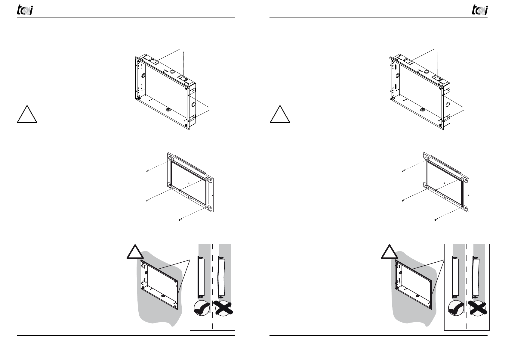
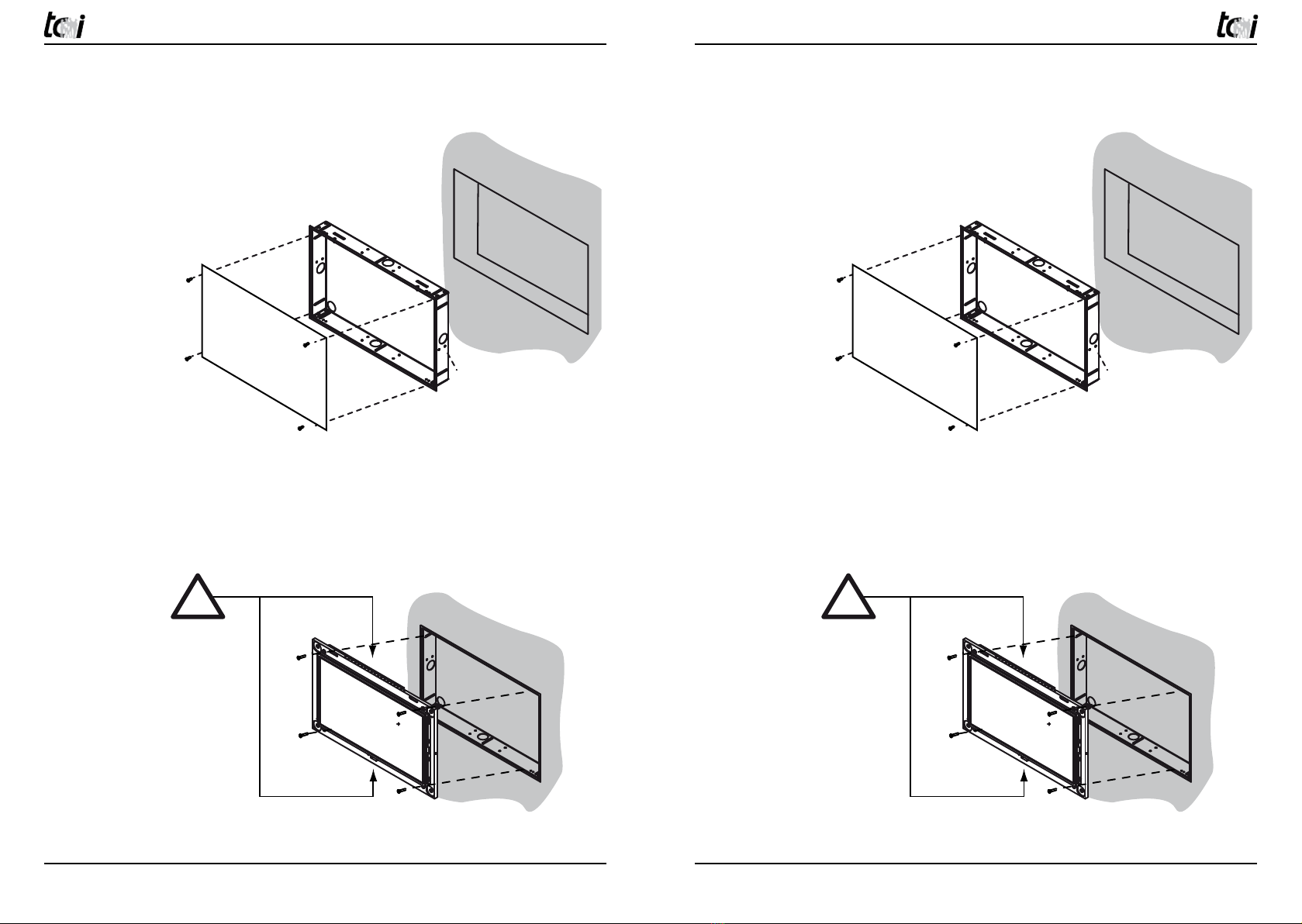
3.2 Vorbereitung der Montage
Einbau des Unterputzgehäuses:
Zum Einbau des Unterputzgehäuses stehen
Ihnen folgende Optionen zur Verfügung:
A) mit den vorhandenen Betonbaulaschen
in massivem Mauerwerk (Option)
B) mit den im Rahmen vorhandenen
Löchern zur Montage in Hohlraum-
wänden.
Empfehlung zur Positionierung des Unterputzgehäuses:
Die richtige Position des Unterputzgehäuse
hängt von Körpergröße des Benutzers ab.
Wir empfehlen: Displaymitte ~ 1650 mm
vom fertigen Fußboden
Ausbau aus dem Unterputzgehäuse:
Entfernen Sie die 4 Schrauben und nehmen
Sie den Wmura aus dem Unterputzgehäuse
3.21 Einbau UPG
[UNTERPUTZGEHÄUSE]
Achten Sie bei der Montage darauf, dass
das Unterputzgehäuse bei der Montage
nicht verzogen wird, da sonst beim Einbau
und in der Lebenszeit der ambiento.mura
Schaden nehmen kann.
A (8x)
(optional/optionally)
B (4x)
A (8x)
(optional/optionally)
B (4x)
Wand/Wall
!
Richtig!
OK!
Oui !
Falsch!
Not OK!
Non !
Wand
Wall
Mur
Wand
Wall
Mur
Wand/Wall/Mur
UPG
Wandausschnitt
Mounting hole
Découpe murale
M5x10
Von den Innenseiten verschrauben.
Bolted also from the Insides.
Des intérieurs boulonner.
Wand/Wall
Unterputz-
gehäuse
built-in box
Boîte
d'encastrement
!
Putzschutz
Plastering protection
Protection chantier
!
Wand/Wall
!
Richtig!
OK!
Oui !
Falsch!
Not OK!
Non !
Wand
Wall
Mur
Wand
Wall
Mur
Wand/Wall/Mur
UPG
Wandausschnitt
Mounting hole
Découpe murale
M5x10
Von den Innenseiten verschrauben.
Bolted also from the Insides.
Des intérieurs boulonner.
Wand/Wall
Unterputz-
gehäuse
built-in box
Boîte
d'encastrement
!
Putzschutz
Plastering protection
Protection chantier
!
3.2 Preparation of mounting and installation
Mounting of the built-in box
The two following different options can
used for mounting:
A) by straight plates for plastering into
masonary (optionally).
B) by the holes of the frame into a cavity
wall construction.
Introduction about position of the built-in box:
The position of the built-in box depends of
the body height of the user. We introduce:
Display middle ~ 1650 mm from the fini-
shed ground floor
Dismounting out of the built-in box:
Unscrew the 4 screws and take out the
Wmura
3.21 Mounting UPG
[BUILT-IN BOX]
Please attend that the built-in box not be
warped, because the ambiento.mura can
be demaged by mountingor in his livetime.
!
ACHTUNG: Vorsicht bei der Montage
und Demontage des Frontrahmens.
Der Touch könnte Schaden nehmen
Siehe Kapitel 3.5!
!
ATTENTION: Please be careful be
mounting or dismounting of the front
frame. The touch can be demaged
See chapter 3.5!
Ludwig-Rinn-Straße 10-14 • D- 35452 Heuchelheim/Gießen • Phone: +49 6 41-9 62 84-0 • Fax: +49 6 41-9 62 84-28 • www.tci.de Ludwig-Rinn-Straße 10-14 • D- 35452 Heuchelheim/Gießen • Phone: +49 6 41-9 62 84-0 • Fax: +49 6 41-9 62 84-28 • www.tci.de
Seite 14 von 40 Seite 15 von 40
3.22 Einbau UPG mit Putzschutz
Montage des Touches nach dem Verputzen
Lüftungschlitze an Ober- und Unterseite dürfen nicht verdeckt werden! Sollten durch den
Putz die Lüftungschlitze verdeckt sein, müssen 4 gleichstarke Distanzscheiben verwen-
det werden.
Wand/Wall
!
Richtig!
OK!
Oui !
Falsch!
Not OK!
Non !
Wand
Wall
Mur
Wand
Wall
Mur
Wand/Wall/Mur
UPG
Wandausschnitt
Mounting hole
Découpe murale
M5x10
Von den Innenseiten verschrauben.
Bolted also from the Insides.
Des intérieurs boulonner.
Wand/Wall
Unterputz-
gehäuse
built-in box
Boîte
d'encastrement
!
Putzschutz
Plastering protection
Protection chantier
!
Wand/Wall
!
Richtig!
OK!
Oui !
Falsch!
Not OK!
Non !
Wand
Wall
Mur
Wand
Wall
Mur
Wand/Wall/Mur
UPG
Wandausschnitt
Mounting hole
Découpe murale
M5x10
Von den Innenseiten verschrauben.
Bolted also from the Insides.
Des intérieurs boulonner.
Wand/Wall
Unterputz-
gehäuse
built-in box
Boîte
d'encastrement
!
Putzschutz
Plastering protection
Protection chantier
!
3.22 Mounting UPG with plastering protection
Mounting of the touch after plastering
Don’t cover ventilation slots at the top and bottom side! Should the ventilation slots be
covered by the finery covered, 4 equally strong distance rings must be used.

Ludwig-Rinn-Straße 10-14 • D- 35452 Heuchelheim/Gießen • Phone: +49 6 41-9 62 84-0 • Fax: +49 6 41-9 62 84-28 • www.tci.de Ludwig-Rinn-Straße 10-14 • D- 35452 Heuchelheim/Gießen • Phone: +49 6 41-9 62 84-0 • Fax: +49 6 41-9 62 84-28 • www.tci.de
Seite 16 von 40 Seite 17 von 40
3.23 Einbau EPG [EINPUTZGEHÄUSE]
Bei der Verwendung eines EPG‘s müssen Sie darauf achten, dass
die Oberkannte mit der fertigen Wandfläche abschließt. Die Box
wird von den Innenseiten verschraubt. Eine Nachjustierung des
EPG‘s nach dem verputzen ist daher noch möglich. Da die vordere
Kante des EPG‘s sichtbar bleibt, müssen diese bei der Endbear-
beitung der Wand geschützt werden.
3.3 Montagehinweis
Einbau des ambiento.mura nur durch autorisiertes Fachpersonal und Elektriker.
Die tci GmbH kann keine Haftung für die montierte Unterputzgehäuse und deren
Funktion übernehmen. Eine Prüfung durch Fachpersonal ist erforderlich.
Montage nur im spannungsfreien Zustand der Zuleitungen.
PE Erdung muss unbedingt angeschlossen werden! Es besteht Lebensgefahr durch einen
elektrischen Schlag, wenn z.B. die Außenhülle der Zuleitung beschädigt ist und das
Gehäuse berührt.
Montagehilfe beim UPG
Sie finden die Montagehilfe im Zubehör-
karton. Sie besteht aus zwei abgewinkelten
Blechen und dafür vorgesehene Schrauben.
Montieren Sie beide Bleche wie in der Ab-
bildung gezeigt in das Unterputzgehäuse an
der Oberseite.
Montagehilfe beim EPG
Wie im Bild gezeigt können Sie mit dem
mitgelieferten Distanzstreifen die Position
des ambientoWmura von der Unterkannte
bestimmem.
! !
3.23 Einbau EPG [EINPUTZGEHÄUSE]
By using an EPG please make sure the top edge fits tightly against
the finished wall. The EPG gets screwed from the inner sides. So
it is possible to readjust the EPG‘s position after plastering. Due to
the fact that the front edge remains visible, it has to be protected
during the completion of the wall.
3.3 Instruction of installation
Mounting of the ambiento.mura only by authorized technical personal and elec-
trician. tci GmbH cannot take over adhesion for the installed built-in box and
their function. An examination by technical personnel is necessary.
Assembly only in the unstressed condition of the inlets.
PE ground must be connected! There is mortal danger by an electrical impact, if the outer
hull of the inlet is damaged e.g. and affects the housing.
Fit-up aid of the UPG
You will find the fit-up aid into the accessory
box. It is consisting of two bent laminations
and therefore useable screws. Please mount
the laminations as figured into the built-in
box on the top side. The distance between
fit-up aid and built-in box would be 5 mm.
Fit-Up aid of the EPG
This picture show how you have to use
distance parts to positioning the ambien-
toWmura from the bottom edge.
ambiento10Wmura
Front
ambiento10Wmura
EPG: Einputzkasten zum
flächenbündigen Einbau
Built-in box, flush mounting
with the adjacent areas
190
302
201 mm
313 mm
183 mm
287 mm
21 mm
43 mm
189 mm
293 mm
181 mm
285 mm
48 mm
UPG: Unterputzkasten
built-in box
Rev.: 1.1 | 01.06.2010
ambiento10Wmura
Front
ambiento10Wmura
EPG: Einputzkasten zum
flächenbündigen Einbau
Built-in box, flush mounting
with the adjacent areas
190
302
201 mm
313 mm
183 mm
287 mm
21 mm
43 mm
189 mm
293 mm
181 mm
285 mm
48 mm
UPG: Unterputzkasten
built-in box
Rev.: 1.1 | 01.06.2010
Ludwig-Rinn-Straße 10-14 • D- 35452 Heuchelheim/Gießen • Phone: +49 6 41-9 62 84-0 • Fax: +49 6 41-9 62 84-28 • www.tci.de Ludwig-Rinn-Straße 10-14 • D- 35452 Heuchelheim/Gießen • Phone: +49 6 41-9 62 84-0 • Fax: +49 6 41-9 62 84-28 • www.tci.de
Seite 18 von 40 Seite 19 von 40
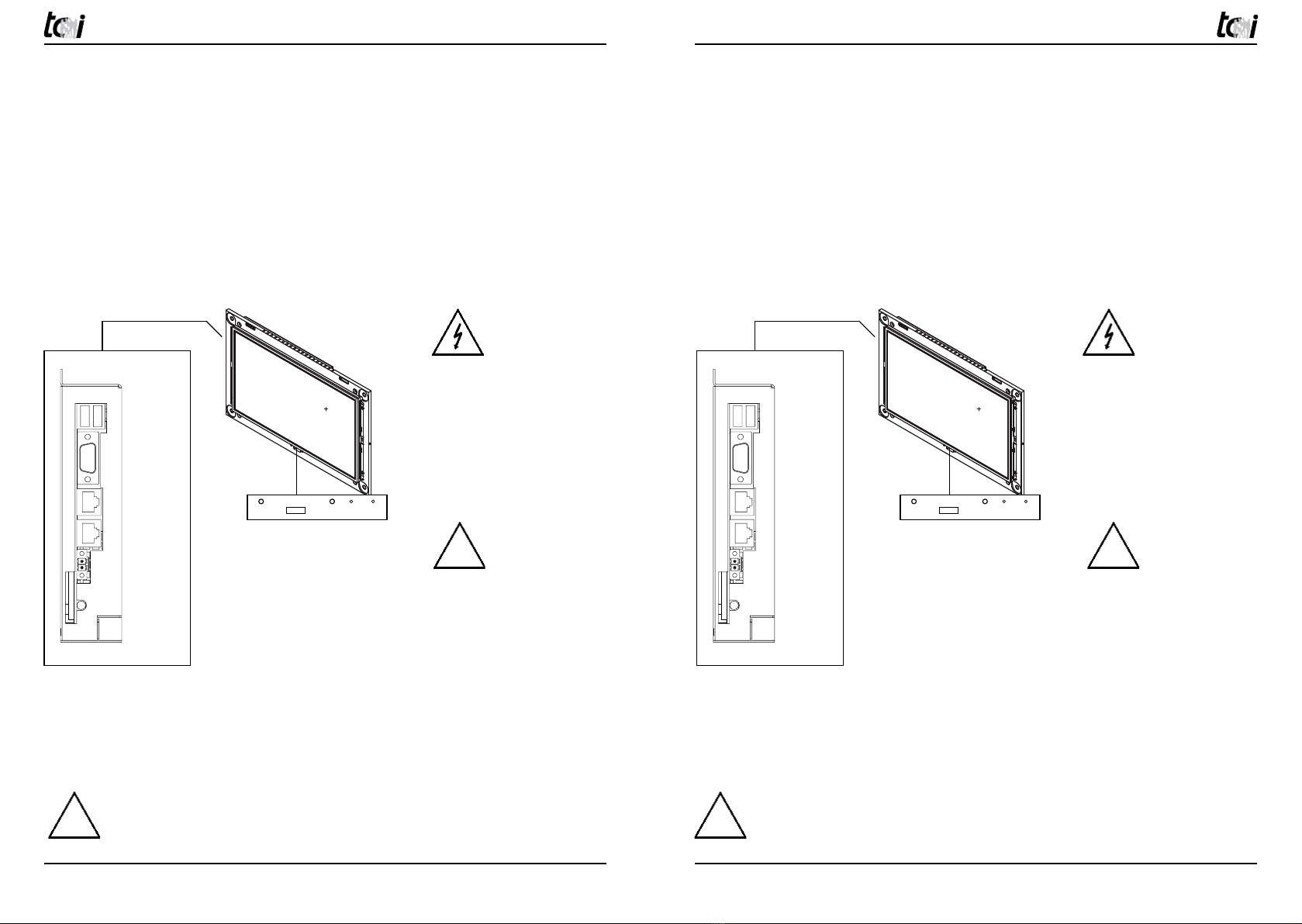
3.4 Montage und Schnittstellen
Anschluss der Versorgungsleitungen an das Gerät:
Bevor Sie das Gerät in den Unterputzgehäuse einbauen, müssen alle benötigten Versor-
gungsleitungen gemäß dieser Abbildung anschließen. Bitte achten Sie auf den korrekten
Anschluss der Stromversorgung, der passende Anschlussstecker ist im Lieferumfang
enthalten. An der Front befindet sich USB-Anschluss, optional CAM oder WLAN.
Montage im Unterputzgehäuse:
Befestigen Sie den Wmura mit den 4 Schrauben, die Sie bei der „Vorbereitung der Mon-
tage“ Kapitel 3.2 entfernt haben. Sofern der Unterputzgehäuse vorab geliefert wurde,
befinden sich die Schrauben beim Zubehör.
Achtung: Touchbedienung
Wir empfehlen bei aktiviertem Powersavingmode = Backlights aus, zusätzlich den
Screensaver mit gleicher Zeit einzustellen. Sie verhindern damit, dass beim aktivieren des
Touches auch ein Button in Ihrer Visualisierung gedrückt wird.
Achtung: MULTITOUCH
Es kann zu Störungen des Touches kommen, wenn die Front im Betrieb
montiert oder demontiert wird! Erst im stromlosen Zustand Front montieren/
demontieren.
3.4 Mounting and interfaces
Connection of cable to the unit:
Before you mount the unit into the built-in box you have to connect the cables as fol-
lowing picture. Please attend of correct connection of the power input, the specified plug
is part of the delivery. On the front you have USB connection and optionally CAM or
WLAN
Mounting into the built-in box:
Fasten ambiento.mura with the 4 screws, which removed you during „ preparation of the
mounting and installation “chapter 3.2. If the built-in box was delivered first, the screws
will be found into the accessory box.
Attention: Touch using
We recommend by activated Power saving mode = Backlights off additionally use the
same time by the Screensaver. That prevent by activation the touch also use a button in
your visualization.
Attention: MULTITOUCH
It may be come problems to the touch when the front will be mount or dismount
in the operating. Only in power off state front mount / remove.
! !
USB
COM 1
LAN2
LAN/PoE
Power In
12-27V DC
Audio
SD
KNX(optional)
USB
Reset Power
ON/OFF
Orange
DC-IN
Grün/green
PowerOn
USB
COM 1
LAN2
LAN/PoE
Power In
12-27V DC
Audio
SD
KNX(optional)
USB
Reset Power
ON/OFF
Orange
DC-IN
Grün/green
PowerOn
Empfehlungen:
LAN/PoE mit anliegender
Spannung nicht gleichzeitig
mit Power In 12-27 VDC
verwenden
LAN2 nicht mit PoE
betreiben.
Setzen Sie jetzt die Zulei-
tung wieder unter Span-
nung. Das Gerät sollte bei
einwandfreier Spannungs-
versorgung nach dem
Einschalten starten.
Introduction:
Do not use LAN/PoE with
voltage at the same time
with Power In 12-27 VDC.
Do not connect LAN2 to
PoE.
Now you can supply the
cables with power. The unit
will be start automatically
after pushing the power
button.
! !
Ludwig-Rinn-Straße 10-14 • D- 35452 Heuchelheim/Gießen • Phone: +49 6 41-9 62 84-0 • Fax: +49 6 41-9 62 84-28 • www.tci.de Ludwig-Rinn-Straße 10-14 • D- 35452 Heuchelheim/Gießen • Phone: +49 6 41-9 62 84-0 • Fax: +49 6 41-9 62 84-28 • www.tci.de
Seite 20 von 40 Seite 21 von 40
3.5 Installation/Erste Inbetriebnahme
Remote-Desktop
1) verbinden Sie den ambientoWmura mit Ihrem Netzwerk.
Die Defaulteinstellung des ambientoWmura ist:
LAN1: DHCP
LAN2: IP: 192.168.0.20 / 255.255.255.0
2) Stellen Sie nun die Spannungsversorgung her, das System bootet das Betriebssystem
automatisch*
3) Der ambientoWmura meldet sich automatisch in Ihrem Netzwerk an und kann mit
diesen Zugangsdaten konfiguriert werden:
Computer Name: tci-pc
User Name: tci
Passwort: tci
* Hinweise:
a) Unter bestimmten Voraussetzungen kann dieser Vorgang bei der ersten Inbetrieb-
nahme einige Minuten dauern, da Treiber sich automatisch konfigurieren müssen. In
diesem Zustand reagieren Tastatur und Maus nicht.
BIOS Konfiguration tci-Baseboard
Im Auslieferungszustand ist das BIOS optimal eingestellt.
Alle Änderungen im BIOS auf eigene Gefahr und sind nicht im Gewähr-/Garantieleistungs-
umfang enthalten.
!
Niemals im Bios
ändern/ausführen:
Internal Flat Panel type unter Chipset Configuration
3.5 First installation
via Remote-Desktop
1) Connect the ambientoWmura to your network.
The default setting ot the ambientoWmura is:
LAN1: DHCP
LAN2: IP: 192.168.0.20 / 255.255.255.0
2) Now connect to the power input, the system will be started automaticly the operating
system*
3) The ambientoWmura will be connected in your network and can be configurated with
the following login:
Computer Name: tci-pc
User Name: tci
Password: tci
* advices
a) Under certain conditions this procedure can take some minutes with first start-up,
since drivers must configure themselves automatically. In this condition keyboard and
mouse do not react.
BIOS configuration tci-Baseboard
On delivery the BIOS is optimally adjusted.
All changes in the BIOS on own danger and are not contained in the guarantee/guaranting
extent.
!
Never change/use
on Bios:
Internal Flat panel type under chip set Configuration
Ludwig-Rinn-Straße 10-14 • D- 35452 Heuchelheim/Gießen • Phone: +49 6 41-9 62 84-0 • Fax: +49 6 41-9 62 84-28 • www.tci.de Ludwig-Rinn-Straße 10-14 • D- 35452 Heuchelheim/Gießen • Phone: +49 6 41-9 62 84-0 • Fax: +49 6 41-9 62 84-28 • www.tci.de
Seite 22 von 40 Seite 23 von 40
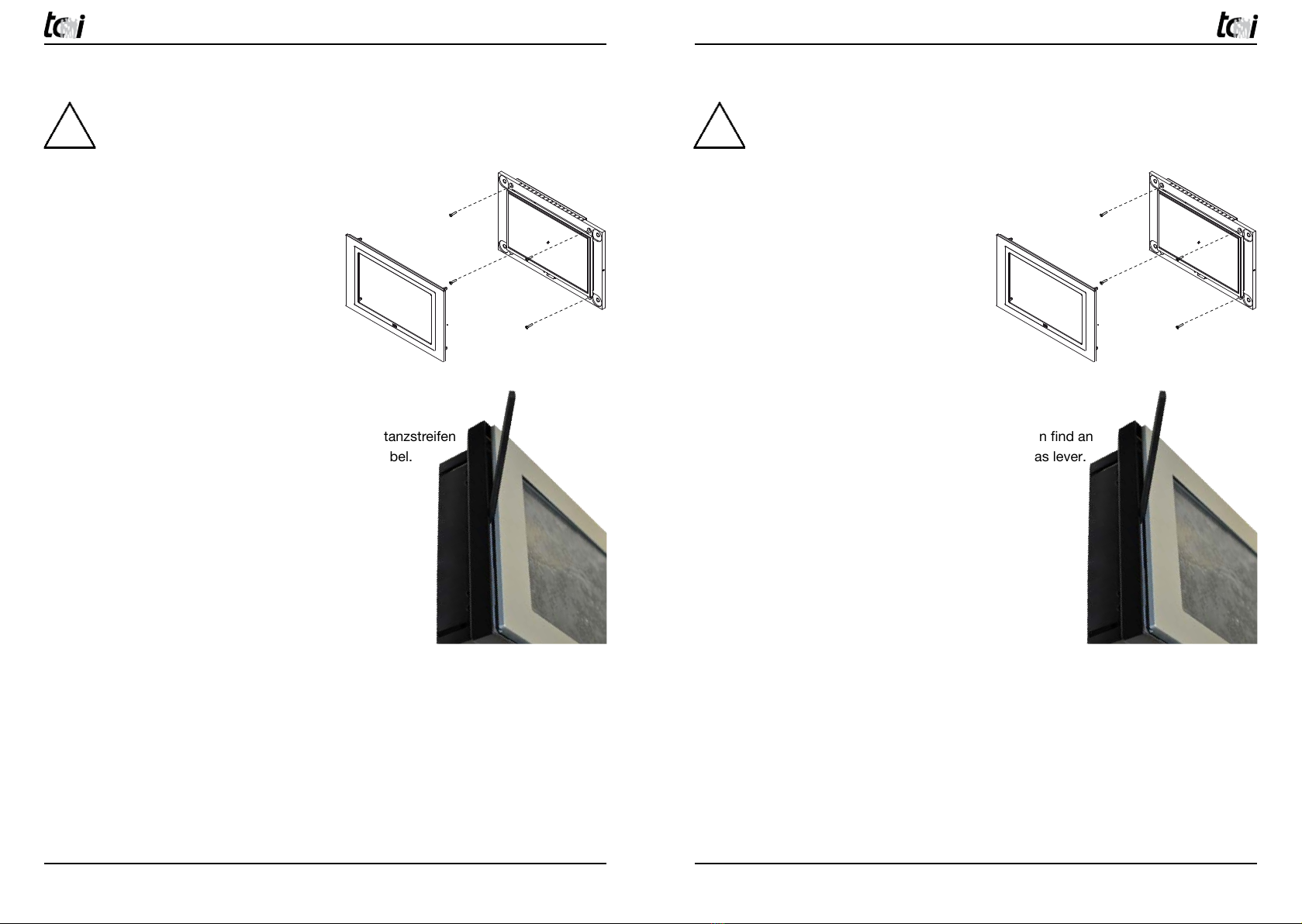
3.6 Final assembly/cleaning and care
Now you can separate the protection foil.
Don’t cover the ventilation slots of the top and bottom side!
Please mount with the screws M5x25 the
Wmura into the built-in box and remove the
distance strips.
Afterwards push the front with the 4 rivets
into the holes. Don‘t cant because the touch
can be demaged.
Dismounting of the front: At the parts of delivery you can find an
distance strip with an an beleved end. Please use that as lever.
Cleaning and care of the touch
On the desktop or the provided data storage you will find the
software called touchblocker. With this software the touch will be
blocked for 60 sec. In this time you can clean the touch with yield
cloth without cleaning agents
Cleaning and care of the front frame
For the care and cleaning only suitable cleaning agents may be used.
3.6 Endmontage/Reinigung und Pflege
Sie können jetzt die Schutzfolie von der Front entfernen.
Lüftungsschlitze an der Ober- und Unterseite niemals verdecken!
Montieren Sie mit den mitgelieferten
Schrauben M5x25 den Wmura in das
Unterputzgehäuse oder Einputzgehäuse.
Entfernen Sie die Distanzstreifen bei wieder.
Drücken Sie anschließend die Front mit den
Schnappnieten in die dafür vorgesehenen
Bohrungen. Nicht verkannten sont droht ein
Schaden am Touch.
Demontage der Front: Im Zubehör finden Sie einen Distanzstreifen
der leicht angeschrägt ist. Verwenden Sie diesen als Hebel.
Reinigung und Pflege des Touches
Auf dem Desktop bzw. auf dem mitgelieferten Datenträger befin-
det sich eine Software mit dem Namen Touchblocker. Durch diese
Software wird der Touch für 60 Sekunden blockiert. In dieser Zeit
haben Sie die Möglichkeit den Touch mit einem weichen Tuch ohne
Reinigungsmitteln zu säubern.
Reinigung und Pflege der Frontrahmen
Für die Pflege und Reinigung dürfen nur geeignete Reinigungsmittel eingesetzt werden.
! !
Ludwig-Rinn-Straße 10-14 • D- 35452 Heuchelheim/Gießen • Phone: +49 6 41-9 62 84-0 • Fax: +49 6 41-9 62 84-28 • www.tci.de Ludwig-Rinn-Straße 10-14 • D- 35452 Heuchelheim/Gießen • Phone: +49 6 41-9 62 84-0 • Fax: +49 6 41-9 62 84-28 • www.tci.de
Seite 24 von 40 Seite 25 von 40
3.7 KNX/EIB Schnittstelle
Anwendung
Die Schaltung dient der Herstellung einer bidirektionalen Datenverbindung zwischen dem
logico (USB Anschluss intern) und dem Installationsbus EIB/KNX. Der USB-Anschluss ist
vom KNX Bus galvanisch getrennt. Die Schaltung ist kompatibel mit dem KNX Medium
TP1 (EIB), die Firmware unterstützt das Protokoll EMI1.
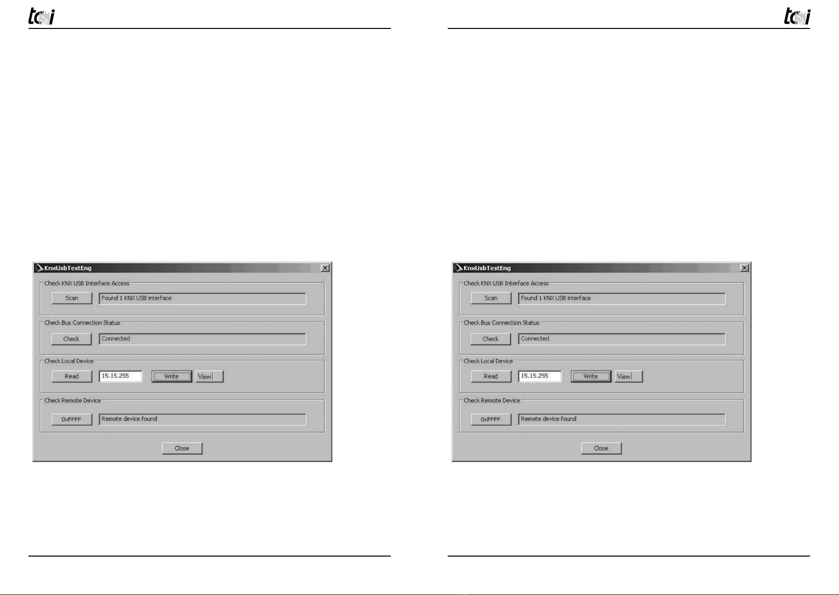
3.71 Manuelle Einrichtung der KNX Schnittstelle
(Optional)
Zur manuellen Umstellung der KNX-Adresse können Sie das knxtool.ambiento.de ein
Softwaretool downloaden.
Wenn Sie die Software öffnen sehen sie dieses Fenster:
Die Schaltfläche „View“ ermöglicht die Umschaltung zwischen DEC- und HEX-Darstellung
für die Adresse. Tragen Sie die neue Adresse in das Feld ein und klicken Sie anschließend
auf die Schaltfläche „Write“.
3.7 KNX/EIB Interface
Purpose
This board is used to establish a connection between logico and the installation bus EIB/
KNX. The USB connector has a galvanic separation from the EIB/KNX bus. The circuit is
compatible with KNX medium TP1 (EIB), the firmware supports protocol EMI1.
3.71 Manuel configuration of the KNX interface
(Optionally)
For manual changing of the KNX adress you can download under knxtool.ambiento.de a
software tool
After open the software you will see this window:
The button „View“ offers the possibility to change between DEC and HEX of the adress.
Please enter now the new adress into the field and confirm with „Write“.

Ludwig-Rinn-Straße 10-14 • D- 35452 Heuchelheim/Gießen • Phone: +49 6 41-9 62 84-0 • Fax: +49 6 41-9 62 84-28 • www.tci.de Ludwig-Rinn-Straße 10-14 • D- 35452 Heuchelheim/Gießen • Phone: +49 6 41-9 62 84-0 • Fax: +49 6 41-9 62 84-28 • www.tci.de
Seite 26 von 40 Seite 27 von 40
3.8 ICOM und CAM
Mit der Option ICOM und CAM können Sie das System zum Freisprechen als Gegen-
sprechanlage für eine IP-Sprechanlage nutzen. Entsprechende Einstellungen können Sie
über die Windows Systemeinstellungen ändern.
Bei der Option CAM ist oberhalb des Displays eine USB-Kamera eingebaut. Bitte beach-
ten Sie bei der Reinigung, dass das Kamera-Auge nicht beschädigt wird.
3.9 BacklightControl
BacklightControl ist ein Tool zur Steue-
rung der Backlight Helligkeit und verfügt
über 2 verschiedene Modi [Mode]:
1. Manuell: Hier kann die Helligkeit
direkt eingestellt werden.
2. Auto : Im Auto Mode wird die Hel-
ligkeit in Abhängigkeit der Umgebung
automatisch geregelt.
BacklightControl benötigt das DotNET Framework sowie den Dienst GIVEIO.SYS und Easi.dll
Funktionsbeschreibung Auto Mode:
Im automatischen Modus wird die Backlight Helligkeit an den vom Helligkeitssensor gelesenen Wert
angepasst. BacklightControl erkennt anhand des Helligkeitssensors wann „Tag“ und wann „Nacht“ ist
und setzt die Helligkeit des Backlights auf die dafür vorgesehenen Werte.
Sensor Wert „Tag“ Backlight wird auf den maximalen Helligkeitswert gesetzt. Der maximale Hellig-
keitswert des Backlights wird aus der eingestellten Helligkeit im manuellen Modus übernommen.
Sensor Wert „Nacht“ Backlight wird auf den minimalen Helligkeitswert gesetzt. Der minimale Hellig-
keitswert entspricht der eingestellten Schrittweite.
Sensor Grenzwerte Tag/Nacht
Die Sensor Grenzwerte für „Tag“ und „Nacht“ können im Teachmode konfiguriert werden. Der Teach-
mode kann über das Optionsmenü aktiviert werden. Ist der Teachmode aktiv kann der momentan
vom Helligkeitssensor gelesene Wert als Grenzwert für „Tag“ oder „Nacht“ mit einem Klick auf den
jeweiligen Button übernommen werden.
3.8 ICOM and CAM
With the options ICOM and CAM you can use handsfree the system as IP based intercom
system. By speaking the integrated micro will be open and you can contact the visitor.
Changings can be made in the Windows System properities.
The option CAM is a USB-camera modul, which is integrated on the top of the display.
Please attend by cleaning that the eye of the cam not be damaged.
3.9 BacklightControl
BacklightControl is a tool to the control-
ling of the Backlight brightness a have 2
different modes [Mode]:
1. Manually: Here the brightness can be
stopped directly.
2. Automatic : In the automatic mode is
regulated automatically the brightness
according the environment.
Dependence: BacklightControl needs the DotNET Framework as well as the service GIVEIO.SYS and
Easi.dll
Description of function auto mode:
In the automatic mode the Backlight brightness is adapted to the value read from the brightness
sensor. BacklightControl recognizes day on the basis the brightness sensor when „“and when „night
“is and sets the brightness of the Backlights on the values planned for it:
Sensor value „day “ Backlight is set on the maximum brightness value. The maximum brightness
value of the Backlights is transferred from the adjusted brightness in the manual mode.
Sensor of limit values day/night
The sensor of limit values for „day “and „can be configured to night “in the Teachmode. The Teach-
mode can be activated over the option menu. The Teachmode is can the value momentarily read
from the brightness sensor as limit value for „day “or „night “with one clicks actively on the respective
button to be taken over.

Ludwig-Rinn-Straße 10-14 • D- 35452 Heuchelheim/Gießen • Phone: +49 6 41-9 62 84-0 • Fax: +49 6 41-9 62 84-28 • www.tci.de Ludwig-Rinn-Straße 10-14 • D- 35452 Heuchelheim/Gießen • Phone: +49 6 41-9 62 84-0 • Fax: +49 6 41-9 62 84-28 • www.tci.de
Seite 28 von 40 Seite 29 von 40
Für das folgend bezeichnete Erzeugnis
tci Industrie PC Typ:
wird die Übereinstimmung mit Bestimmungen der nachstehenden EG Richtlinien bestätigt.
- EMV-Richtlinie 2004/108/EG
- Niederspannungsrichtlinie 2006/65/EG
Zur Beurteilung der elektromagnetischen Verträglichkeit des Erzeugnisses wurden folgen-
de Normen herangezogen:
- EN 55022 : 2006 Klasse A
- EN 55024 : 1998 + A1 : 2001 + A2 : 2003
- EN 61000-3-2 : 2006
- EN 61000-3-3 : 1995 + A1 : 2001 + A2 : 2005
- EN 61326-1 : 2006
- EN 60601-1-2 : 2007
- EN 61000-6-2 : 2006-03
- EN 61000-6-3 : 2007-09
Zur Beurteilung der elektrischen Sicherheit wurden folgende Normen herangezogen:
- EN 60950-1 : 2006 + A11 : 2009
Diese Erklärung wird verantwortlich für den Hersteller
tci Gesellschaft für technische Informatik mbH
Ludwig-Rinn-Straße 10 – 14
35452 Heuchelheim
abgegeben durch die Geschäftsleitung
Heuchelheim, 25.03.2010
The product described in this manual
tci Industrial PC Type:
Hereby the agreement with regulations of the following EC guidelines is confirmed.
- EMC directive 2004/108/EG
- Low voltage directive 2006/65/EG
To evaluate the electromagnetic compatibility of these products, the following standards
were taken into consideration:
- EN 55022 : 2006 class A
- EN 55024 : 1998 + A1 : 2001 + A2 : 2003
- EN 61000-3-2 : 2006
- EN 61000-3-3 : 1995 + A1 : 2001 + A2 : 2005
- EN 61326-1 : 2006
- EN 60601-1-2 : 2007
- EN 61000-6-2 : 2006-03
- EN 61000-6-3 : 2007-09
To evaluate the electrical safety of the products, the following standards were taken into consideration:
- EN 60950-1 : 2006 + A11 : 2009
This declaration is made under the sole responsibility of the producer
tci Gesellschaft für technische Informatik mbH
Ludwig-Rinn-Straße 10-14
35452 Heuchelheim
The Management
Heuchelheim, 25th March 2010
3.10 EG-Konformitätserklärung
Wmura
3.10 EC-Declaration of Conformity
Wmura

Ludwig-Rinn-Straße 10-14 • D- 35452 Heuchelheim/Gießen • Phone: +49 6 41-9 62 84-0 • Fax: +49 6 41-9 62 84-28 • www.tci.de Ludwig-Rinn-Straße 10-14 • D- 35452 Heuchelheim/Gießen • Phone: +49 6 41-9 62 84-0 • Fax: +49 6 41-9 62 84-28 • www.tci.de
Seite 30 von 40 Seite 31 von 40
4. Lieferumfang
• Wmura
• Wmura Front, optional
• Unterputzgehäuse, optional (sofern nicht vorab geliefert)
• Montagematerial
• Handbuch
• Touch-Treiber
• Touchblocker
• Treiber und Dokumentationen der eingebauten Hardware
• Optional Betriebssystem
ambientoOS-XPProf: WindowsXP® Professional MUI installiert auf Festplatte
ambientoOS-Win7: Windows7® installiert auf Festplatte,
für 16WmuraMT, Empfehlung: nur mit CPU-Upgrade
ambientoOS-XPEmb: WindowsXP® embedded installiert
ambientoOS-Win7Emb: Windows7® embedded installiert
ambientoOS-LX: Linux
• Recovery CD
4. Scope of Delivery
• Wmura
• Wmura front, optionally
• built-in box, optionally (could be delivered before)
• mounting assembly
• manual
• touch driver
• touchblocker
• driver and documentation of the installed hardware
• optionally operating system
ambientoOS-XPProf: WindowsXP® Professional MUI installed on HDD
ambientoOS-Win7: Windows7® installed on HDD, for 16WmuraMT,
Suggestion: only with CPU-Upgrade
ambientoOS-XPEmb: WindowsXP® embedded installed
ambientoOS-Win7Emb: Windows7® embedded installed
ambientoOS-LX: Linux
• Recovery CD
Ludwig-Rinn-Straße 10-14 • D- 35452 Heuchelheim/Gießen • Phone: +49 6 41-9 62 84-0 • Fax: +49 6 41-9 62 84-28 • www.tci.de Ludwig-Rinn-Straße 10-14 • D- 35452 Heuchelheim/Gießen • Phone: +49 6 41-9 62 84-0 • Fax: +49 6 41-9 62 84-28 • www.tci.de
Seite 32 von 40 Seite 33 von 40
5. Support
5.1 Support
Wir unternehmen im Vorfeld alles, um die Funktionsfähigkeit unserer Systeme zu ge-
währleisten. Sorgfältige Auswahl der Komponenten, aufwendige Tests und Prüfverfahren
stellen dies sicher. Dennoch kann es zu Ausfällen kommen. In einem solchen Fall
steht Ihnen unsere Hotline zur Verfügung. Wir helfen schnell und unkompliziert.
Rat und Hilfe bzw. Support erhalten Sie unter der
Telefonnummer E-Mail
0641-96284-55 [email protected]
Wir beantworten Ihre Fragen oder lösen Ihre Probleme so schnell wie möglich.
5.2 Rücksendung
Die richtige Verpackung ist der erste Schritt zur problemlosen Versendung eines Gerä-
tes. Verwenden Sie ausschließlich für Ihre Rücksendungen Original-Verpackungen von
tci, darin enthalten sind 2 Inletts und ein Umkarton. Sollten Sie keine Verpackung mehr
haben, wenden Sie sich bitte an unseren Support.
Unsachgemäß verpackte und dadurch beschädigte Geräte können von der Garantie
ausgeschlossen werden, wenn die Beschädigungen auf die unsachgemäße Verpackung
zurückzuführen ist. Wir empfehlen den Versand mit einer Spedition, da
erfahrungsgemäß hierbei weniger Schäden entstehen. Einen Verpackungshinweis und
einen Reparaturschein finden Sie unter www.tci.de/support.
5. Support
5.1 Support
It is our priority to guarantee the functionality of our systems. This is ensured by a
careful selection of components, extensive inspection and test procedure. However,
errors cannot be completely ruled out. If you should have any problems with your
unit, please do not hesitate to contact our hotline. We will assist you immediately
and without any complications.
You can reach our Support team at
Phone number E-Mail
+49-(0)641-96284-55 [email protected]
We will answer your questions or solve any problems you might have with your unit.
5.2 Dispatch
The right packaging is the first step for a trouble-free dispatch of a device. Please only use
the original tci protective packaging for your returns. Devices that get damaged due to
improper packaging can be excluded from guarantee.
We suggest to task a private forwarding agent with the shipment, because by our experi-
ence the devices get less damaged during the transport.
Further packaging information and a repair form you will find under www.tci.de/support.

Ludwig-Rinn-Straße 10-14 • D- 35452 Heuchelheim/Gießen • Phone: +49 6 41-9 62 84-0 • Fax: +49 6 41-9 62 84-28 • www.tci.de Ludwig-Rinn-Straße 10-14 • D- 35452 Heuchelheim/Gießen • Phone: +49 6 41-9 62 84-0 • Fax: +49 6 41-9 62 84-28 • www.tci.de
Seite 34 von 40 Seite 35 von 40
5.3 Herstellergarantie
Die tci - Gesellschaft für technische Informatik mbH (TCI) gewährt ihrem Käufer eine 12-monatige
Produktgarantie auf von TCI hergestellte Produkte.
Tritt bei einem von TCI hergestellten Produkt innerhalb von 12 Monaten nach Lieferung ein Mangel
auf, wird TCI diesen unter nachgenannten Voraussetzungen nach eigener Wahl entweder durch Liefe-
rung eines Neugerätes, Austausch von Teilen oder durch Reparatur beseitigen.
TCI trägt im Rahmen seiner Garantieleistungen während der Garantiezeit die mit dem Austausch oder
der Reparatur von Produkten oder Produktteilen verbundenen Kosten, soweit der Mangel im Rahmen
einer ordnungsgemäßen Nutzung der Produkte aufgetreten ist. Die Kosten zur Feststellung des Man-
gels beim Käufer sowie des Ein- oder Ausbaus sind vom Käufer zu tragen. Transport und Versand
von Produkten oder Produktteilen erfolgen auf Gefahr und Kosten des Käufers.
Garantiezeiten beginnen jeweils mit dem Tag, an dem die Lieferung des Produktes erfolgt. Die Erbrin-
gung von Garantieleistungen verlängern die Garantiezeiten nicht.
Die im oder zum Austausch gelieferten Produkte oder Produktteile sind neu oder neuwertig und in
einwandfreiem, funktionstüchtigem Zustand; ausgetauschte Produkte oder Produktteile werden mit
Absendung durch TCI oder Abholung der entsprechenden Austauschteile bei TCI deren Eigentum;
der Käufer garantiert, dass Rechte Dritter diesem Austausch und Eigentumsübergang nicht im Wege
stehen.
Ansprüche aus dieser Garantie sind innerhalb von einem Monat ab Kenntnis des Mangels schrift-
lich bei TCI anzumelden. Derzeitige Anschrift ist tci -Gesellschaft für technische Informatik mbH;
Ludwig-Rinn-Straße 10-14; 35452 Heuchelheim / Gießen. Weitergehende Ansprüche, insbesondere
Schadensersatzansprüche, sind von der Garantie nicht umfasst. Die gesetzliche Mängelhaftung bleibt
von der Garantie unberührt. Es gilt das Recht der Bundesrepublik Deutschland unter Ausschluss des
UN-Kaufrechts. Ist der Kunde Kaufmann, ist Gerichtsstand für Streitigkeiten aus dieser Garantie der
Sitz von TCI.
Voraussetzungen für Garantieleistungen:
1. Es handelt sich um einen Mangel, der nach
dem Kauf entstanden ist.
2. Das betreffende Produkt ist über die Serien-
nummer eindeutig identifizierbar.
3. Vorlage des Kaufbelegs.
4. Äußere Faktoren, wie z.B. Brand, Vanda-
lismus, nicht autorisierte Eingriffe, zu hohe
Temperaturen etc., oder normaler Verschleiß
sind als Ursache ausgeschlossen.
5. Das Produkt wurde nicht verändert, ausge-
nommen von autorisierten TCI-Mitarbeitern
/-Partnern.
6. Das Produkt wurde ausschließlich sachgemäß
entsprechend der Bedienung¬sanleitung und
Dokumentation angewendet.
7. Die Installation, Bedienung, Reparatur und
Wartung erfolgt gemäß den von TCI zur Ver-
fügung gestellten Vorgaben. Dies bedeutet im
Einzelnen:
a. Installation, Aufbau und Montage erfolgen
gemäß der Bedienungs- und Montageanlei-
tung und durch eine entsprechende Fachkraft.
b. Eine im Garantiefall notwendige
Reparatur
wird ausschließlich von einem TCI-Mitarbeiter/-
Partner oder mit von tci zur Verfügung gestell-
ten Ersatzteile durchgeführt.
c. Das betreffende Produkt wird ausschließ-
lich in Verbindung mit kompatiblen Produkten
angewendet.
Nicht von der Garantie umfasst:
1. Maßnahmen zur Beseitigung von Störungen,
die auf Bedienungsfehlern, sonstiger unsach-
gemäßer Behandlung, technischen Eingriffen
seitens des Käufers oder Dritter oder auf
äußeren, nicht von TCI zu vertretenden Ein-
flüssen beruhen.
2. Kosten von Austauschteilen, die einem
besonderen Verschleiß unterliegen, von Ver-
brauchsmaterial und von Datenträgern.
3. Instandsetzung von Zubehör, Änderungen,
Anbauten oder sonstigen Einrichtungen, die
nicht von tci geliefert wurden.
4. Instandsetzungsarbeiten, wenn die Umge-
bungs-bedingungen lt. der Dokumentation
nicht eingehalten wurden.
5. Mängel, die durch mangelhafte Systemausle-
gung, Systemkonfiguration und Montageart,
durch den Betrieb unter ungeeigneten Umge-
bungsbedingungen oder sonstigen ungeeig-
neten Betriebsmethoden, durch ungeeignete
Wartung oder ungeeig¬nete Tests oder durch
Einflüsse wie Verunreinigungen bedingt sind.
5.3 Manufacturer’s Guarantee
tci Gesellschaft für technische Informatik mbH (TCI) provides a 12-month product guarantee to the
purchaser, which covers products manufactured by TCI.
Should a defect be determined with a product manufactured by TCI within 12 months after delivery,
then TCI will remove this defect at their own option either by providing a new product, or by replacing
parts or by repairing the product subject to the conditions defined below.
Within the scope of the guarantee, TCI will bear all costs related to the replacement of parts or the
repair of products or product parts during the term of this guarantee, insofar as the defect has oc-
curred during proper use of the product. Any costs incurred for the determining of the defect as well
as costs of mounting and demounting at the customer’s premises are to be borne by the purchaser.
Delivery and dispatch of products or product parts will be effected at the purchaser’s risk and expen-
se. The term of guarantee shall begin from the date of delivery of the product. Any services provided
within the scope of the guarantee do not extend the term of guarantee.
All products or product parts delivered as or for a replacement are new or equivalent to new and in
perfect operative condition; replaced products or product parts will become property of TCI as soon
as they are sent off to or collected by TCI; the purchaser guarantees that there are not any legal im-
pediments to such transfer of product and ownership which might result from third-party rights.
Any claims under this guarantee are to be made to TCI in writing within one month after cognizance
of the defect. Current address: tci -Gesellschaft für technische Informatik mbH; Ludwig-Rinn-Strasse
10-14; 35452 Heuchelheim / Giessen Germany. Any further claims, claims for damages in particular,
are excluded from this guarantee. Statutory liability for defects remains unaffected of this guarantee.
The German law shall apply to all matters related to this guarantee. In case the purchaser is a mer-
chant, place of jurisdiction for any litigation resulting from this guarantee shall be the location of the
registered office of TCI.
Terms of guarantee:
1. Only defects that have occurred after the
purchase are covered by this guarantee.
2. The product in question must be clearly iden-
tifiable by its serial number.
3.
The voucher of the purchase has to be submitted.
4. External factors, e.g. fire, vandalism, unau-
thorized handling, excessive temperatures
etc., or normal wear are excluded from the
guarantee.
5. The product must not have been modified,
ex-
cept by authorized TCI employees or partners.
6. The product has been used exclusively in a
competent way according to the operating
manual and documentation.
7.
Installation, operation, repair, and maintenance
have been performed according to the instructions
and the operating documentation the purchaser
has obtained from TCI. This means in particular:
a. Installation, setup, and mounting have been
performed according to the installation and
operating instructions in the documentation
and by a competent professional.
b. Necessary repair work during the term of
guarantee has been performed exclusively by
a TCI employee or authorized partner or with
spare parts provided by TCI.
c. The product concerned has been used
exclusively in connection with compatible
products.
Excluded from this guarantee are:
1. All measures for the removal of defects that
have been caused by operating mistakes,
other incompetent handling, technical inter-
vention on the part of the purchaser or any
third party or any other external influence TCI
can not be held responsible for;
2. Costs of replacement parts subject to
extreme wear and of consumables and data
carriers;
3. Maintenance or repair of accessories, modi-
fied parts, added parts or any other part that
have not been delivered by TCI;
4. Repair work that has become necessary
because the limits of the environmental spe-
cifications in the documentation have been
exceeded;
5. Defects that have resulted from an inadequate
system layout, system configuration, and type
of mounting, or from operation under inappro-
priate environmental conditions or from other
inappropriate operating methods or from
incompetent maintenance or inappropriate
tests or from influences like contamination.
Ludwig-Rinn-Straße 10-14 • D- 35452 Heuchelheim/Gießen • Phone: +49 6 41-9 62 84-0 • Fax: +49 6 41-9 62 84-28 • www.tci.de Ludwig-Rinn-Straße 10-14 • D- 35452 Heuchelheim/Gießen • Phone: +49 6 41-9 62 84-0 • Fax: +49 6 41-9 62 84-28 • www.tci.de
Seite 36 von 40 Seite 37 von 40
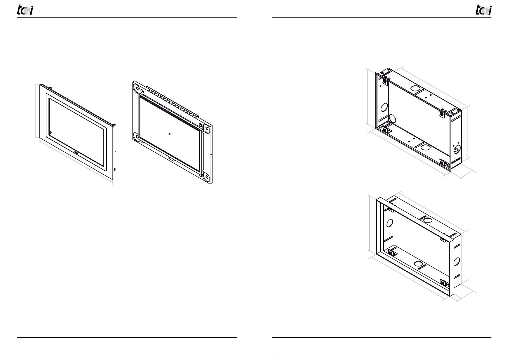
6. Technische Zeichnung / Technical Drawing
6.1 10Wmura
ambiento10Wmura
Front
ambiento10Wmura
EPG: Einputzkasten zum
flächenbündigen Einbau
Built-in box, flush mounting
with the adjacent areas
190
302
201 mm
313 mm
183 mm
287 mm
21 mm
43 mm
189 mm
293 mm
181 mm
285 mm
48 mm
UPG: Unterputzkasten
built-in box
Rev.: 1.1 | 01.06.2010
ambiento10Wmura
Front
ambiento10Wmura
EPG: Einputzkasten zum
flächenbündigen Einbau
Built-in box, flush mounting
with the adjacent areas
190
302
201 mm
313 mm
183 mm
287 mm
21 mm
43 mm
189 mm
293 mm
181 mm
285 mm
48 mm
UPG: Unterputzkasten
built-in box
Rev.: 1.1 | 01.06.2010
Alle Maßangaben ohne Kabeldurchführungen und Betonbaulaschen!
All measure data without cable entries and plates for plastering!
Ludwig-Rinn-Straße 10-14 • D- 35452 Heuchelheim/Gießen • Phone: +49 6 41-9 62 84-0 • Fax: +49 6 41-9 62 84-28 • www.tci.de Ludwig-Rinn-Straße 10-14 • D- 35452 Heuchelheim/Gießen • Phone: +49 6 41-9 62 84-0 • Fax: +49 6 41-9 62 84-28 • www.tci.de
Seite 38 von 40 Seite 39 von 40
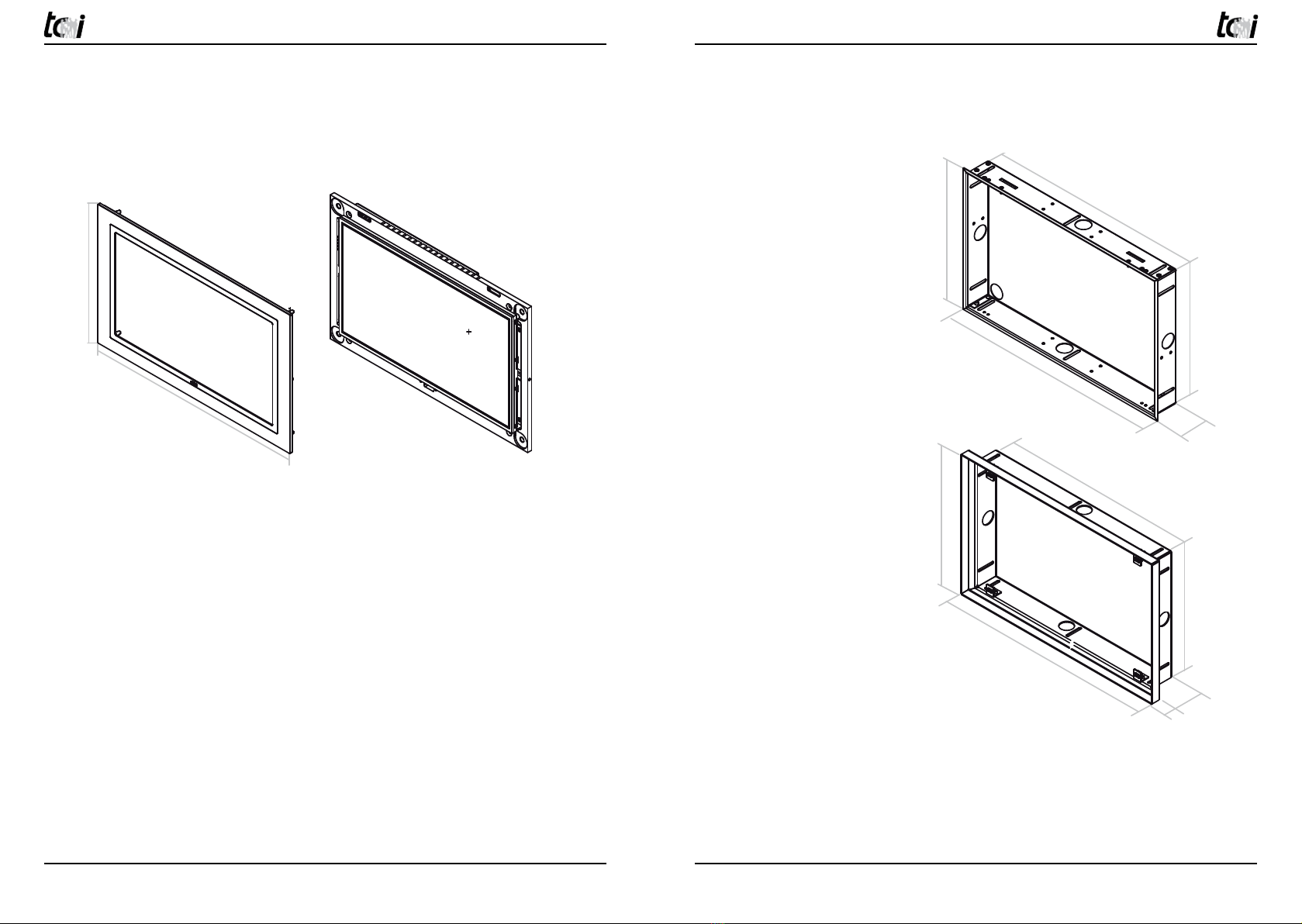
6.2 16Wmura
ambiento16Wmura
Front
ambiento16Wmura
EPG: Einputzkasten zum
flächenbündigen Einbau
Built-in box, flush mounting
with the adjacent areas
UPG: Unterputzkasten
built-in box
266
424
277 mm 260 mm
435 mm
411 mm
250 mm
401 mm
21 mm
43 mm
248 mm
399 mm
48 mm
Rev.: 1.1 | 01.06.2010
ambiento16Wmura
Front
ambiento16Wmura
EPG: Einputzkasten zum
flächenbündigen Einbau
Built-in box, flush mounting
with the adjacent areas
UPG: Unterputzkasten
built-in box
266
424
277 mm 260 mm
435 mm
411 mm
250 mm
401 mm
21 mm
43 mm
248 mm
399 mm
48 mm
Rev.: 1.1 | 01.06.2010
Alle Maßangaben ohne Kabeldurchführungen und Betonbaulaschen!
All measure data without cable entries and plates for plastering!
This manual suits for next models
2
Table of contents
Other TCi Control Unit manuals


Popular Control Unit manuals by other brands


Edwards
Edwards SIGA-CC2 Installation sheet

MD
MD mXion TLSpro user manual

Schmalz
Schmalz SCPi Brief operating instructions

Immergas
Immergas Trio Base V2 Instructions and warnings

Telit Wireless Solutions
Telit Wireless Solutions HE910 Hardware user's guide

Texas Instruments
Texas Instruments SN65HVD257 user guide


