HBX ECO-1000 Operating instructions

Page 1
©HBX Control Systems Inc. 2015
Phone: +1 (403) 720-0029 Fax: +1 (403) 720-0054
Email: info@hbxcontrols.com Web: www.hbxcontrols.com
HBX Control Systems Inc.
4516 - 112th Avenue SE
Calgary, AB Canada T2C 2K2
HBX Control Systems Inc.
ECO-1000
Central Processing Unit 1000
Version 1.35
Solar Programming Guide

HBX ECO-1000 HVAC Control
Version 1.35
Page 2
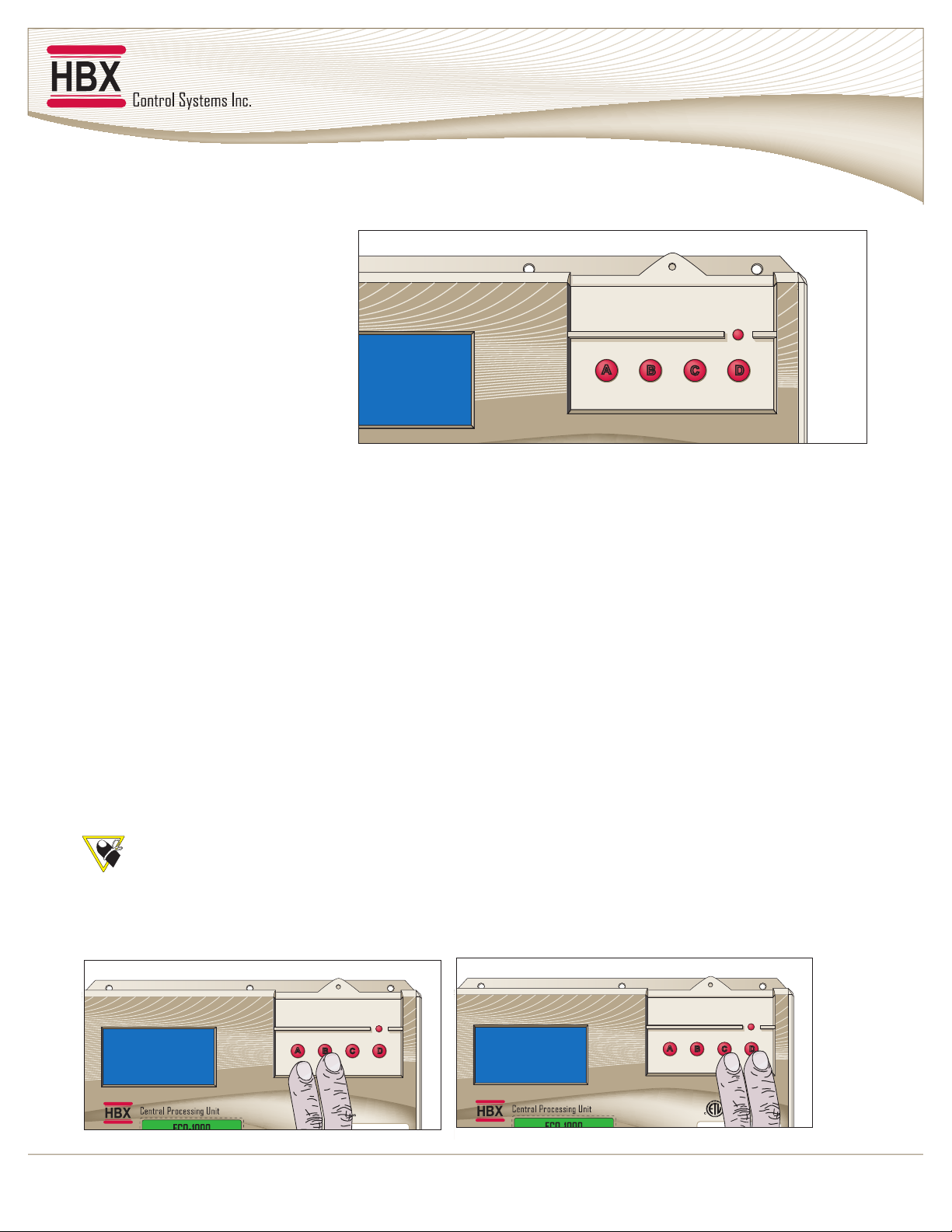
NAVIGATING THE CONTROL
The four large red buttons labeled “A”, “B”, “C”, and “D” are used to make your way through the programming
options within the Control.
Pressing the “A” or “B” button while
viewing the initial “System Status” and
“System Function” main screens will
swap from screen to screen. Pressing
the “D” button will take you to the
“Programming Options” screen.
Pressing the “D” button again will
revert to the main system screens.
Once in the “Programming Options”
menu you may move the selection
indicator up and down by pressing the A and B buttons, pressing the “C” button will enter the selected option.
Pressing the “C” button on options with limited choices (ie. on/off, yes/no) will toggle the selection.
Pressing the “A” and “B” buttons on options with variable numerical choices (ie. temperature values, time settings)
will increase and decrease the selected amount. Pressing the “C” button upon completion will forward you to the next
step.
The “D” button can be used to revert to the previous menu.
AAB
BC
CD
D
Input: 120VAC 60Hz 5A
Relays: 240VAC 10A
Demand Signal: 20 - 240V
Model: CPU - 1000
CAUTION,
RISK OF ELECTRICAL SHOCK - DISCONNECT POWER PRIOR TO SERVICING
Certified to CSA C22.2 No 24
Conforms to UL Standard 873
Central Processing Unit
ECO-1000
Program Lock Feature
To minimize the potential for unauthorized tampering of your control after commissioning, you have the ability to
limit/lock the programming menus.
To lock the control, use two ngers to press and hold down the A and B buttons simultaneously for approximately 10
secs.
To unlock the control, use two ngers to press and hold down the C and D buttons simultaneously for approximately
10 secs.
at the same time.
AAB
BC
CD
D
Input: 120VAC 60Hz 5A
Relays: 240VAC 10A
Demand Signal: 20 - 240V
Model: CPU - 1000
CAUTION,
RISK OF ELECTRICAL SHOCK - DISCONNECT POWER PRIOR TO SERVICING
Certified to CSA C22.2 No 24
Conforms to UL Standard 873
AAB
BC
CD
D
Input: 120VAC 60Hz 5A
Relays: 240VAC 10A
Demand Signal: 20 - 240V
Model: CPU - 1000
CAUTION,
RISK OF ELECTRICAL SHOCK - DISCONNECT POWER PRIOR TO SERVICING
Certified to CSA C22.2 No 24
Conforms to UL Standard 873

HBX ECO-1000 HVAC Control
Version 1.35
© HBX Control Systems Inc. 2015 Page 3
- This signal is only used in a
geothermal application as a heat demand signal.
- This signal is only used in a
geothermal application as a cooling demand signal.
- This signal is only used in a
geothermal application, for a fault indicator.
- Tank Sensor
- GND loop or cold tank sensor
for geothermal applications, solar sensor in solar
applications.
- Outdoor Sensor / return sensor for
solar.
- Used for a reversing valve in geothermal
applications or as solar pump 2 in a solar system.
- Used as a geo-circulating pump in a
geothermal application or as solar pump 1 in a solar
system.
- Used as a geothermal circulating pump or
tank 1 pump in a solar system.
- the 3-wire 120VAC input to the
control. Protected by a 30Amp breaker or fuse.
- This relay is the default relay for
bringing on the rst geothermal stage, or the solar
backup.
- This relay is the default relay for
bringing on the 2nd geothermal stage or for a hi temp
dump contact in a solar system.
21
SD
1
SD
1
43
SD
2
SD
2
65
SD
3
SD
3RG
021
82
N
L
7262
RG
021
52
N
L
4232
RG
021
22
N
L
1202
RG
021
91
N
L
8171
LR
2
LR
6151
2
LR
1
LR
4131
1
MT
3
MT
2111
3
MT
2
MT
019
2
MT
1
MT
87
1
v042-02 v042-02 v042-02
EREHREWOPTCENNOCTONOD
A01 A01
A01 A01A01
0001OCE
XBH TINUGNISSECORPLARTNEC
yaleR3P
yaleR2P
yaleR1P
CAV021rewoPylppuS
2yaleR:csiM
1yaleR:csiM
1langiSdnameD
2langiSdnameD
3langiSdnameD
1rotsimrehT
2rotsimrehT
3rotsimrehT
Terminal Designations for ECO-1000

Control Systems Inc.
Comfort
Control
Innovation
HBX ECO-1000 HVAC Control
Version 1.34
Page 4
Programming
PROGRAMMING
The HBX display is a 128 x 64 pixel, back-lit graphic display on a blue background.
In addition to displaying text and icons it has the ability to provide you with visual
graphing capabilities. These graphing capabilities will allow you to get representative
data and trending information of up to 2 independent feedback values.
System Status
Tank 1
System
Return
Setpnt 1
162
180
167
72
Target
º
F
ºF
ºF
ºF
170
120
SP1 SP2 SP3
Mon Feb 14 2011 12:00:45
Target
Temperature
Shown in
Column below
Real Time and Date Shown
Temperature Feedback
( deg. Fahrenheit shown)
Setpoint ON Indicator

Page 5
Selecting the solar option will setup the ECO-1000 to display all options applicable to a solar
application.
2B2B
Choose Control Type
1) GeoThermal
2) Solar
This screen will be visible for approximately 5 seconds to identify the application you have
selected.
1.26
Temperatures visible depend on the settings currently active.
4B4B
TARGET
Tank 1 open °F 226
System open °F 200
Return open °F
Setpnt1 open °F
System Status
WED FEB 11 2009 11:07:02
The ECO-1000 can be congured as either a Geothermal or Solar specic hydronic control.
This screen will only stay on the rst time you power up the control. This screen will display
for ve seconds each time the control is started after you have selected the control type.
Choose Control Type
1) Geothermal
2) Solar
System function displays currently active solar pumps, heat pumps and dumps.
You can toggle between main screens by pressing either the “A” or “B” button.
5B5B
CYCLES
Solar Pump1 ON 1
Solar Pump2 ON 1
Tank 1 Pump OFF 0
Backup OFF 0
Dump ON 1
System Function
1) Control Options
2) Solar Options
3) Change Designs
4) Setpoint Options
5) Setback Options
6) Graphing
7B7B
1) Control Options
2) Solar Options
3) Change Designs
4) Setpoint Options
5) Setback Options
6) Graphing
Programming
The third system screen displays extra sensors if applicable in your system.
66
Target
Extra OFF °F
Extra OFF °F
System Status

Page 6
The control options area contains options for changing the display, setting constant heat/
cooling demands; testing/viewing activity and enabling zone control. To enter the desired
selection, press the “C” button. For example, with line 1 ashing, press button “C” to enter
the “Control Options screen”.
8B8B
1) Control Options
2) Solar Options
3) Change Designs
4) Setpoint Options
5) Setback Options
6) Graphing
Programming
Select the appropriate year by pressing the “A” button to decrease and the “B” button to
increase the year. Press the “C” button to proceed.
1212
Year 2000
Display options allow you to: set your date and time; reset the internal relay counter for
pump and heat pump cycles; program and display either ºF or ºC; program the Control
to allow for Daylight Savings; access website information for HBX; and clear the stage
accumulated hours counter.
9B9B
1) Display Options
2) Always HD? N
3) Always HD2? N
4) Mins and Maxs
5) Testing
6) Stage Run Times
7) Use Zone Module? N
Control Options
Display options allow you to: set your date and time; reset the internal relay counter for
pump and heat pump cycles; program and display either ºF or ºC; program the Control
to allow for Daylight Savings; access website information for HBX; and clear the stage
accumulated hours counter.
1010
1) Change Time
2) Reset Cycles
3) Display in °F
4) D-lite savings? N
5) Contact HBX
6) Reset Run Times
Display Options
It is recommended that you setup the correct time on your Control before conguring other
options, as the real-time settings are effected by the “Change Time” feature.
1111
1) Change Time
2) Reset Cycles
3) Display in °F
4) D-lite savings? N
5) Contact HBX
6) Reset Run Times
Display Options
Select the appropriate month (1-12) by pressing the “A” button to decrease and the “B”
button to increase the month. Press the “C” button to proceed.
1313
Month 00
Select the appropriate day of the month (1-31) by pressing the “A” button to decrease and
the “B” button to increase the day. Press the “C” button to proceed.
1414
Day 00

Page 7
Pressing the “C” button with the “Reset Cycles” option selected will reset the internal relay
counter for heat pumps and heat pump cycles. Heat pump and pump cycles are visible on
the “System Function” screen.
1) Change Time
2) Reset Cycles
3) Display in °F
4) D-lite savings? N
5) Contact HBX
6) Reset Run Times
Display Options
18
18
Pressing the “C” button with the “Display in °F/°C” option selected will allow you to
program the Control and display in either ºF or ºC scales.
1919
1) Change Time
2) Reset Cycles
3) Display in °C
4) D-lite savings? N
5) Contact HBX
6) Reset Run Times
Display Options
Pressing the “C” button with the “D-Lite Savings” option selected will allow you to program
the Control to allow for Daylight Savings time shifting.
2020
1) Change Time
2) Reset Cycles
3) Display in °F
4) D-lite savings? Y
5) Contact HBX
6) Reset Run Times
Display Options
Pressing the “C” button with the “Contact HBX” option selected will display the
manufacturer contact information and the units individual serial number.
2121
1) Change Time
2) Reset Cycles
3) Display in °F
4) D-lite savings? N
5) Contact HBX
6) Reset Run Times
Display Options
Select the appropriate day of the week (1-7) by pressing the “A” button to decrease and the
“B” button to increase the day. Press the “C” button to proceed.
1515
Weekday 1
(Sunday = 1)
Select the appropriate hour of the day (0-24) by pressing the “A” button to decrease and the
“B” button to increase the hour. Press the “C” button to proceed.
1616
Hour 00
Select the appropriate minute of the hour (0-60) by pressing the “A” button to decrease and
the “B” button to increase the minute. Press the “C” button to proceed.
1717
Min 00

Page 8
Contact HBX Controls directly and display your Controls serial number
2222 HBX Control Systems
Calgary, AB, Canada
1-403-720-0029
www.hbxcontrols.com
ID Serial: xxxxxxxxxx
Press B to Continue
Pressing the “C” button with the “Reset Run Times” option selected will clear the stage
accumulated hours counter. To view the stage runtime, select the “Stage Run Times” option
within the “Control Options” menu.
2323
1) Change Time
2) Reset Cycles
3) Display in °F
4) D-lite savings? N
5) Contact HBX
6) Reset Run Times
Display Options
Not applicable for solar applications.
24B24B
1) Display Options
2) Always HD? Y
3) Always HD2? N
4) Mins and Maxs
5) Testing
6) Stage Run Times
7) Use Zone Module? N
Control Options
Not applicable for solar applications.
25B25B
1) Display Options
2) Always HD? N
3) Always HD2? Y
4) Mins and Maxs
5) Testing
6) Stage Run Times
7) Use Zone Module? N
Control Options
Allows you to look at a maximum of six different thermistor min/max temperature extremes
and reset back to zero. To see updated Min/Max values return to the System Status screen to
refresh the view.
2727
1) Thermistor 1
2) Thermistor 2
3) Thermistor 3
4) Thermistor 4
5) Thermistor 5
6) Thermistor 6
7) Reset All
Mins and Maxs
Each thermistor has its highest and lowest temperatures stored, as well as the time that this
temperature was reached and the period of time that it spent at this value.
2828
01/01/09 Min Temp
00HRS 223˚F
01/01/09 Max Temp
00HRS 223˚F
Thermistor 1
When formatting the Control existing min/max values are reset. Selecting the “Reset All”
option clears the time and date stamps.
2929
1) Thermistor 1
2) Thermistor 2
3) Thermistor 3
4) Thermistor 4
5) Thermistor 5
6) Thermistor 6
7) Reset All
Mins and Maxs

Page 9
This allows you to manually test/run each relay for up to 30 seconds.
30B30B
1) Display Options
2) Always HD? N
3) Always HD2? N
4) Mins and Maxs
5) Testing
6) Stage Run Times
7) Use Zone Module? N
Control Options
This allows you to view extreme temperatures that the thermistor has been subjected to.
These values can be reset at any time.
26B26B
1) Display Options
2) Always HD? N
3) Always HD2? N
4) Mins and Maxs
5) Testing
6) Stage Run Times
7) Use Zone Module? N
Control Options
There are ve relays on the main control box. Relays six and higher will be run with
the corresponding Expansion Module connected. By continually pressing the “A”
button you can access extra screens showing Relays #8 and higher.
3131
1) Relay #1
2) Relay #2
3) Relay #3
4) Relay #4
5) Relay #5
6) Relay #6
7) Relay #7
Testing
The third screen is displayed by pressing the “A” button on the last selection of the
previous screen. PWM relays are accessible here.
3232 16) Relay #16
17) Relay #17
18) PWM #1
19) PWM #2
20) PWM #3
21) PWM #4
22) PWM #5
This screen informs you that the Control is reverting the relays to an off state.
3333
Waiting for relays
to turn off
This allows you to view cumulative run times for your heat pump stages. This is reset in the
“Display Options” menu.
35B35B
1) Display Options
2) Always HD? Y
3) Always HD2? N
4) Mins and Maxs
5) Testing
6) Stage Run Times
7) Use Zone Module? N
Control Options
Pressing the “C” button on selected relays will activate the test sequence.
3434
Relay 1 is on

Page 10
This screen will display staging runtimes in a geothermal system, and the backup system
runtime in a solar installation.
Press the “D” button to exit
3636
1) 0:00
Stage Run Times
This option is not available in this mode of operation.
37B37B
1) Display Options
2) Always HD? Y
3) Always HD2? N
4) Mins and Maxs
5) Testing
6) Stage Run Times
7) Use Zone Module? N
Control Options
The solar options menu provides settings specic to your solar installation.
1) Control Options
2) Solar Options
3) Change Designs
4) Setpoint Options
5) Setback Options
6) Graphing
Programming
38B
38B
This option allows you to setup hot water tanks in your solar system.
1) Tank Settings
2) Solar Settings
3) Differential
Solar Options
39B
39B
The ECO-1000 can control up to 4 storage tanks (individually), this option allows you to set
the number.
1) # of Control Tanks
2) Start Temp
3) Step Temp
4) Min (Backup) Temp
5) Backup OFF Temp
6) Max (Dump) Temp
Tank Settings
40B
40B
Use the “A” and “B” button to set the number of tanks, press “C” once complete. Allows
1-4 tanks.
Number of Tanks
To be Controlled
41B
41B
1
If you are controlling multiple tanks, this is the starting temperature for all tanks. Each tank
will be brought up individually to meet the temperature before raising the target by adding
the step temperature to it.
1) # of Control Tanks
2) Start Temp
3) Step Temp
4) Min (Backup) Temp
5) Backup OFF Temp
6) Max (Dump) Temp
Tank Settings
42B
42B

Page 11
Set this temperature to be the initial heat value for the tanks.
If only 1 control tank is being used, set this temperature to be the max desired in the tank.
Starting Tank Temp
43B
43B
70°F
Step temperature is used in multiple tank applications. Once each tank has reached the target
tank temperature the step temperature is added to the target to increase the target for each
tank.
1) # of Control Tanks
2) Start Temp
3) Step Temp
4) Min (Backup) Temp
5) Backup OFF Temp
6) Max (Dump) Temp
Tank Settings
44B
44B
Choose the desired value for each step to raise the target temperature in multiple tank
applications. The step temperature will be added to the target when all tanks have reached
the target temperature.
Tank Step Temp
45B
45B
10°F
This setting is used if there is a backup present in the system.
1) # of Control Tanks
2) Start Temp
3) Step Temp
4) Min (Backup) Temp
5) Backup OFF Temp
6) Max (Dump) Temp
Tank Settings
46B
46B
Set this value to be the minimum start temperature for a backup system to start.
Minimum Tank Temp
47B
47B
70°F
This setting allows you to designate the temperature that the backup will shut off. This will
allow you to setup the control to achieve the greatest return from a solar system before
relying on the backup.
1) # of Control Tanks
2) Start Temp
3) Step Temp
4) Min (Backup) Temp
5) Backup OFF Temp
6) Max (Dump) Temp
Tank Settings
48B
48B
This setting allows you to designate the temperature that the backup will shut off. This
temperature works in conjunction with the min backup temperature value.
Backup Off Temp
49B
49B
70°F

Page 12
This value is set to the maximum temperature that you desire within the tank.
1) # of Control Tanks
2) Start Temp
3) Step Temp
4) Min (Backup) Temp
5) Backup OFF Temp
6) Max (Dump) Temp
Tank Settings
50B
50B
This is the maximum temperature that you desire within the tank. After this temperature
is achieved the dump contact will close, allowing heat to be taken out of the system before
overheating occurs.
Maximum Tank Temp
51B
51B
190°F
These options are specic to solar installations.
1) Tank Settings
2) Solar Settings
3) Differential
Solar Options
52B
52B
This value is set to the minimum solar temperature at the start of a solar cycle.
1) Min Solar
2) Max Solar
3) Solar Pump2 ON Temp
4) Min Solar Pump Time
Solar Temp Settings
53B
53B
This value should be the temperature at that the solar panel to achieves before turning on the
solar pump. It is only valid if there has been no temperature in the solar panel for 4+ hours.
54B54B Minimum Solar Temp
100°F
This setting will be the maximum solar temperature. After this temperature is achieved the
dump contact will close, allowing heat to be taken out of the system before overheating
occurs.
1) Min Solar
2) Max Solar
3) Solar Pump2 ON Temp
4) Min Solar Pump Time
Solar Temp Settings
55B
55B
Set this value to be the temperature that causes the dump contact to close once it has been
achieved.
56B56B Maximum Solar Temp
200°F

Page 13
Once this user dened temperature is reached, the second solar pump will turn on.
1) Min Solar
2) Max Solar
3) Solar Pump2 ON Temp
4) Min Solar Pump Time
Solar Temp Settings
57B
57B
Set this to be the temperature that you wish the second solar pump to turn on at. This pump
will start if the solar temperature is above the selected temperature, and will shut off if it is
below.
58B58B Solar Pump2 ON Temp
50°F
This setting is only used when auto differential is turned on (see “Differential” settings
within the “Solar Options” menu). This is the min time that the solar pump is desired to
run.
1) Min Solar
2) Max Solar
3) Solar Pump2 ON Temp
4) Min Solar Pump Time
Solar Temp Settings
59B
59B
Set this to the min time that you desire to run the solar pump. This setting is used to
calculate the auto differential which optimizes the temperature recovery in a solar system
(see next step).
60B60B Min Solar Pump Time
Only Used For
Auto Differential
2 mins
This is the temperature setting for the temperature differential between the solar panel
temperature and storage tank temperature.
1) Tank Settings
2) Solar Settings
3) Differential
Solar Options
61B
61B
Set this temperature to be the minimum difference consistently desired between solar panel
temperature and storage tank temperature.
62B62B Differential Temp
4°F
Some features in this menu are not applicable in solar applications
6363
1) Control Options
2) Solar Options
3) Change Designs
4) Setpoint Options
5) Setback Options
6) Graphing
Programming

Page 14
You have the ability to work with up to 3 different setpoints. The default is set to “Off ”.
Select which setpoint you are going to operate, then press the “C” button to enter. Each
system setpoint is congured in the same manner.
6767
1) Setpoint 1 OFF
2) Setpoint 2 OFF
3) Setpoint 3 OFF
4) Merge Setpoints? N
Setpoint Options
Setpoints give you the option to utilize an independent heat/cool demand such as a fancoil,
hot tub or spa. HBX Expansion Modules are required to run setpoints.
6666
1) Control Options
2) Solar Options
3) Change Designs
4) Setpoint Options
5) Setback Options
6) Graphing
Programming
When selected, all of the original settings are reloaded as in the “Factory Defaults” option.
In addition, the “Format Control” option will reset the designated functions for each
terminal.
6464
1) Manual
2) Format Control
Programming
This screen is your nal opportunity to avoid formatting the options within the Control.
6565 CAUTION
All Settings will
be RESET to FACTORY
Settings
Press B to Continue
Press C to EXIT
By selecting choice #1, you will pick the actual setpoint temperature to control around ± the
differential.
6868
1) Setpoint Temp
2) Heating
3) Cool Interlock? N
4) Differential
5) Lag Time
6) Demand Temp
Setpoint 1 Program
Enter value to correspond with setpoint temp thermistor/sensor location.
6969 Setpoint 1 Temp
OFF
Any changes to setpoint controls will prompt you to install one of the HBX Expansion
Modules Eg. EXP-0100 or EXP-0300.
7070 CAUTION
This Setting requires
An Extra module
Press B To Continue

Page 15
Choice #2 allows you to select either heating or cooling mode. Press “C” to toggle between
choices, eg. heating/cooling.
- when the temperature drops below the setpoint, the relays engage.
- when the temperature rises above the setpoint, the relays engage
7171
1) Setpoint Temp
2) Cooling
3) Cool Interlock? N
4) Differential
5) Lag Time
6) Demand Temp
Setpoint 1 Program
If selected “Y”, this will allow cooling only and not a simultaneous heat demand. If selected
“N”, then heating and cooling can be delivered to the same zone space. Eg. tile oor
warming and air conditioning.
7272
1) Setpoint Temp
2) Heating
3) Cool Interlock? Y
4) Differential
5) Lag Time
6) Demand Temp
Setpoint 1 Program
Choice #4 “Differential” will allow you to set your margin for error in ºF or ºC around the
setpoint temperature.
7373
1) Setpoint Temp
2) Heating
3) Cool Interlock? N
4) Differential
5) Lag Time
6) Demand Temp
Setpoint 1 Program
Setpoint differential value is the temp value which the Control will turn on and off around
the setpoint. In this example of 2ºF with a setpoint of 68ºF, the Control will turn on when
the temp falls below 67ºF and turn off when the temp rises above 69ºF.
7474 Setpoint 1 Diff’ntial
2°F
Choice #5 is “Lag Time”. This allows you to set a minimum off time between setpoint
demands. This helps to establish a cycle length between heat demands and reduce short
cycling.
7575
1) Setpoint Temp
2) Heating
3) Cool Interlock? N
4) Differential
5) Lag Time
6) Demand Temp
Setpoint 1 Program
You have a range of 0 to 600 seconds for lag time, and is adjustable in 5 second increments.
7676 Setpoint 1 LagTime
0 S
Set this option to the desired tank temperature when the setpoint engages. This option can
be set to “No Demand”, or from 1-200ºF.
7777
1) Setpoint Temp
2) Heating
3) Cool Interlock? N
4) Differential
5) Lag Time
6) Demand Temp
Setpoint 1 Program

Page 16
“Merge Setpoints” is set to “Y” if you wish to have setpoints 1 and 2 output to the same
Expansion Module. This would be used to effectively save space, increasing the number of
heat pumps that the Control can manage.
79
79
1) Setpoint 1 ON
2) Setpoint 2 OFF
3) Setpoint 3 OFF
4) Merge Setpoints? Y
Setpoint Options
You must have more than two modules attached to the control to merge the setpoints. There
must also be an even number of heat pumps in the system.
8080 CAUTION
Can’t Merge Setpoints
Not enough modules
for thermistors
Press B To Continue
Not applicable in solar mode
8181
1) Control Options
2) GeoThermal Options
3) Change Designs
4) Setpoint Options
5) Setback Options
6) Graphing
Programming
When set to “NO Demand”, there is no call for a hot or cold tank.
7878 Setpoint Demand Temp
No Demand
You have the option to look at the “Load Graph” (Actual vs. Target).
8383
1) Load Graph
2) Source Graph
Graphing
The display allows you to get a visual impression of how your system is performing.
8282
1) Control Options
2) GeoThermal Options
3) Change Designs
4) Setpoint Options
5) Setback Options
6) Graphing
Programming
The Y and X axis are not adjustable. The dotted line represents the target temperature and
the solid line represents the actual temperature. One full screen will display approx 10 mins
of temperature data in 10 sec intervals.
Source Graph °F
90
200
8484

HBX ECO-1000 HVAC Control
Version 1.35
© HBX Control Systems Inc. 2015 Page 17
• Single tank solar system
• Using backup and hi temp dump.
CENTRAL PROCESSING UNITECO-1000
12
DS
1
DS
1
34
DS
2
DS
2
56
DS
3
DS
3GR
120
28
NL
2726
GR
120
25
NL
2423
GRGR
120
22
NL
2120
120
19
NL
1817
RL
2
RL
1615
2
RL
1
RL
1413
1
TM
3
TM
1211
3
TM
2
TM
109
2
TM
1
TM
87
1
20-240 v 20-240 v 20-240 v
DO NOT CONNECT POWER HERE
10 A 10 A
10 A 10 A 10 A
Main
Solar
Pump
P1
Backup
Hi Temp
Dump
Contact
120VAC L
N
Tank
Sensor
Solar
Sensor
Solar
Return
Sensor
120VAC
BBC
CD
D
Input:120VAC 60Hz 5A
Relays: 240VAC 10A
DemandSignal: 20- 240V
Model: CPU - 1000
CAUTION,
RISK OF ELECTRICAL SHOCK - DISCONNECT POWER PRIOR TO SERVICING
Certifiedto CSA C22.2 No 24
Conformsto UL Standard 873
Central Processing Unit
ECO-1000
Multiple
Panel
Application
Supply
Sensor
DHW
Out
Cold
Water In
Electrical
Pump Legend:
• P1 - Solar Pump

HBX ECO-1000 HVAC Control
Version 1.35
Page 18
• Four tank solar system
• Running backup and hi temp dump
EXP-0300
34
DS
1
DS
1
20-240 v
DO NOT
CONNECT
POWER
HERE
TM
1
TM
21
1
EXP. MODULE
GR
120
13
NL
1211
GR
120
10
NGRNL
98
120
7
L
65
10 A 10 A
EXP-0300
34
DS
1
DS
1
20-240 v
DO NOT
CONNECT
POWER
HERE
TM
1
TM
21
1
EXP. MODULE
GR
120
13
NL
1211
GR
120
10
NGRNL
98
120
7
L
65
10 A 10 A
EXP-0300
34
DS
1
DS
1
20-240 v
DO NOT
CONNECT
POWER
HERE
TM
1
TM
21
1
EXP. MODULE
GR
120
13
NL
1211
GR
120
10
NGRNL
98
120
7
L
65
10 A 10 A
CENTRAL PROCESSING UNITECO-1000
12
DS
1
DS
1
34
DS
2
DS
2
56
DS
3
DS
3GR
120
28
NL
2726
GR
120
25
NL
2423
GRGR
120
22
NL
2120
120
19
NL
1817
RL
2
RL
1615
2
RL
1
RL
1413
1
TM
3
TM
1211
3
TM
2
TM
109
2
TM
1
TM
87
1
20-240 v 20-240 v 20-240 v
DO NOT CONNECT POWER HERE
10 A 10 A
10 A 10 A 10 A
Tank 1
Pump
Main Solar
Pump
Tank 2
Pump
Tank 3
Pump
Tank 4
Pump
P1 P2 P3 P4 P5
Backup
120VAC L
N
Tank 1
Sensor
Tank 2
Sensor
Tank 3
Sensor
Tank 4
Sensor
Solar
Sensor
Solar
Return
Sensor
120VAC
120VAC
Certifiedto CSA C22.2 No 24
Conformsto UL Standard 873
Input:120VAC 60Hz 2A
Relays: 240VAC 10A
DemandSignal: 20- 240V
Model: EXP-0300
CAUTION, RISKOF ELECTRICAL SHOCK -
DISCONNECTPOWER PRIOR TO SERVICING
EXP-0300
Expansion Module
Certifiedto CSA C22.2 No 24
Conformsto UL Standard 873
Input:120VAC 60Hz 2A
Relays: 240VAC 10A
DemandSignal: 20- 240V
Model: EXP-0300
CAUTION, RISKOF ELECTRICAL SHOCK -
DISCONNECTPOWER PRIOR TO SERVICING
EXP-0300
Expansion Module
Certifiedto CSA C22.2 No 24
Conformsto UL Standard 873
Input:120VAC 60Hz 2A
Relays: 240VAC 10A
DemandSignal: 20- 240V
Model: EXP-0300
CAUTION, RISKOF ELECTRICAL SHOCK -
DISCONNECTPOWER PRIOR TO SERVICING
EXP-0300
Expansion Module
AA B
B C
C D
D
Input:120VAC 60Hz 5A
Relays: 240VAC 10A
DemandSignal: 20- 240V
Model: CPU - 1000
CAUTION,
RISKOF ELECTRICAL SHOCK - DISCONNECT POWER PRIOR TO SERVICING
Certifiedto CSA C22.2 No 24
Conformsto UL Standard 873
AA
AA
AA
AA
AA
AA
AA
AA
AA
AA
AA
AA
A
A
A
A
A
A
A
A
A
A
A
A
A
A
AA
A
A
A
A
A
A
A
A
A
A
A
AA
A
A
B
B
B
D
D
D
D
D
DD
D
Central Processing Unit
ECO-1000
Backup
Boiler
Multiple
Panel
Application
Solar
Sensor
DHW
Out
Cold
Water In
P1
P2
P3 P4 P5
Pump Legend:
• P1 - Tank 1 Pump
• P2 - Solar Pump
• P3 - Tank 2 Pump
• P4 - Tank 3 Pump
• P5 - Tank 4 Pump
Electrical

HBX ECO-1000 HVAC Control
Version 1.35
© HBX Control Systems Inc. 2015 Page 19
• Two tank solar system
• Running hi temp dump
• Using solar boost pump
EXP-0300
34
DS
1
DS
1
20-240 v
DO NOT
CONNECT
POWER
HERE
TM
1
TM
21
1
EXP. MODULE
GR
120
13
NL
1211
GR
120
10
NGRNL
98
120
7
L
65
10 A 10 A
CENTRAL PROCESSING UNITECO-1000
12
DS
1
DS
1
34
DS
2
DS
2
56
DS
3
DS
3GR
120
28
NL
2726
GR
120
25
NL
2423
GRGR
120
22
NL
2120
120
19
NL
1817
RL
2
RL
1615
2
RL
1
RL
1413
1
TM
3
TM
1211
3
TM
2
TM
109
2
TM
1
TM
87
1
20-240 v 20-240 v 20-240 v
DO NOT CONNECT POWER HERE
10 A 10 A
10 A 10 A 10 A
Tank 1
Pump
Tank 2
Pump
Main
Solar
Pump
Solar
Boost
Pump
P1 P4P2 P3
Backup
120VAC L
N
Tank 1
Sensor
Solar
Sensor
Solar
Return
Sensor
Tank 2
Sensor
120VAC
120VAC
Certifiedto CSA C22.2 No 24
Conformsto UL Standard 873
Input:120VAC 60Hz 2A
Relays: 240VAC 10A
DemandSignal: 20-240V
Model: EXP-0300
CAUTION, RISKOF ELECTRICAL SHOCK -
DISCONNECTPOWER PRIOR TO SERVICING
EXP-0300
Expansion Module
AA B
B C
C D
D
Input:120VAC 60Hz 5A
Relays: 240VAC 10A
DemandSignal: 20-240V
Model: CPU - 1000
CAUTION,
RISKOF ELECTRICAL SHOCK - DISCONNECT POWER PRIOR TO SERVICING
Certifiedto CSA C22.2 No 24
Conformsto UL Standard 873
AA
AA
AA
AA
AA
AA
AA
AA
AA
AA
AA
AA
A
A
A
A
A
A
A
A
A
A
A
A
A
A
A
A
A
A
A
A
A
A
A
A
A
A
A
A
A
A
A
A
A
AA
A
B
B
B
D
D
D
D
DD
D
Central ProcessingU nit
ECO-1000
Backup
Boiler
Cold
Water In
Multiple
Panel
Application
Solar Sensor
DHW
Out
P1
P2
P3
P4
Electrical
Pump Legend:
• P1 - Tank 1 Pump
• P2 - Solar Pump
• P3 - Solar Boost Pump
• P4 - Tank 2 Pump

Page 20
©HBX Control Systems Inc. 2015
Phone: +1 (403) 720-0029 Fax: +1 (403) 720-0054
Email: info@hbxcontrols.com Web: www.hbxcontrols.com
HBX Control Systems Inc.
4516 - 112th Avenue SE
Calgary, AB Canada T2C 2K2
v3.4
Other manuals for ECO-1000
1
Table of contents
Other HBX Control Unit manuals
Popular Control Unit manuals by other brands

Mortara
Mortara WAM user manual

Strand
Strand Vision.Net DMX quick start guide

Amersham Pharmacia Biotech
Amersham Pharmacia Biotech INV-907 instructions

Allen-Bradley
Allen-Bradley ArmorBlock 1732E-8IOLM12R Wiring diagrams

Skipper
Skipper SB-100-SA Installation and operation manual

VAT
VAT 111 Series Installation, operating, & maintenance instructions