Field WiringInformation
Below isthe typical wiringdiagramforthe3-phase
reactorapplied tothefrontend oftheVariable
Frequency Drive(VFD).
Single-phaseapplicationsareacceptable,howev
er,itisimportanttosizetheunitbasedonthe sin
gle phaseFull Load AmperageoftheVFD.The
inputandoutputconnectionsshouldbe on termi
nalsAand Ctoensureproperperformance.
Product Specifications
WiringDiagram
LOAD
LINE
*Forsingle-phaseapplications,usecoils
AandC.IsolateterminalsB1andB2.
u3-Phase,600VoltClass
uULRecognized;FileE-116124
uCEMarked
uCSACertified
uCurrent-rated device
u200%rated currentfor3minutes
uAmbient Temperature:40°C
u
Patented BobbinConstruction on
unitssmallerthan 110 amps
uDistributedGapTechnology
TCIrecommendsthatthesereactorsbe
wiredandlocatedasclosetothefrontendof the
VFDaspossibletohavethegreatest success in
bothprotectingtheVFDaswellasmitigatingline
harmonics.Werecommendthisbe10feetof
cableorless.
Instandard40°Cambientorless installa-
tions,aclearanceof3inchesonallsidesofthe
reactorsanditsenclosureisrecommendedfor
assistinginheatdissipationandamplewire
bendingspace.Thisisageneralguidelinefor
typicalapplications.Ifthe reactorisbeing
installednexttoaheatsensitiveinstrumentor
controldevice,werecommendreviewingspecif-
icrequirementsorheatlimitations.Linereactor
heat loss informationisavailableinthestandard
TCIproductliteratureoronthe webat
www.transcoil.com.
Thesereactorsaredesigned tobefloor-
mounted,orwall-mounted.Large open-style
devicesshouldbepanelmountedbyincorporat-
ingabracketthat wouldactasashelftosupport
thereactorand/orenclosure. Wheninstallingan
openstyledeviceinanexistingcontrolcabinet,
drivecabinet, motorcontrolcenter,orotherlarge
enclosure,thereactorshouldbemountedinthe
lowerhalfofthecabinettopreventhotspotsor
pocketsofheat. Locatingthereactorinthelower
halfofthecabinettypicallyallowsbetterthermal
dissipationandheatconvection.
KLR/KDRLineReactor
InstallationInstruction
INPUT
RecommendationsandConsiderations
WheninstallingtheKLR/KDRLineReactorson
the INPUT sideoftheVariableFrequency Drive
(VFD),pleaseusethefollowingguidelineswhen
wiringtheunit:
TheKLR/KDR LineReactorisa3-phase
deviceandshouldbewiredinseriesandposi-
tionedontheinputsideoftheVFD.
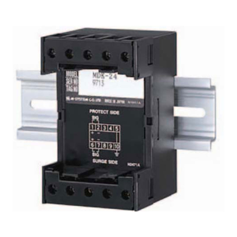
AllTerminalBlock connectorswill be
marked. A1,B1,andC1aretheinputterminals
wherethe3phasesof incomingpoweraretobe
wired.Asaresult,A2,B2,andC2aretheout-
putterminals.Unitswithcopperbusorringlug
terminalsarenotmarked.Inthesecases,either
theupperterminalsorthelowerterminalscan
beusedastheinputterminals,aslongasthe
selectionisconsistent. Forexample,ifanupper
terminalisselectedastheinput, all uppertermi-
nalsmustbeinputterminals.Wiringfromthe
outputterminalsshouldconnecttotheinputof
theVFD.
RefertoNECwiringpracticesforappro-
priatewiresizesforyourapplication.
PowerWiring:Onlyuse75°Ccopper
conductors,unless thewireconnectorismarked
forAI/Cu,thentheuseofaluminumwireisper-
mitted.
