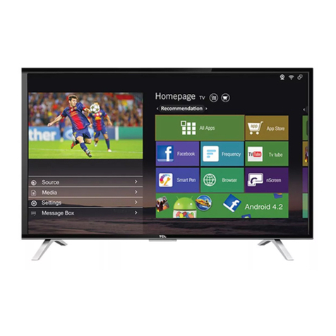
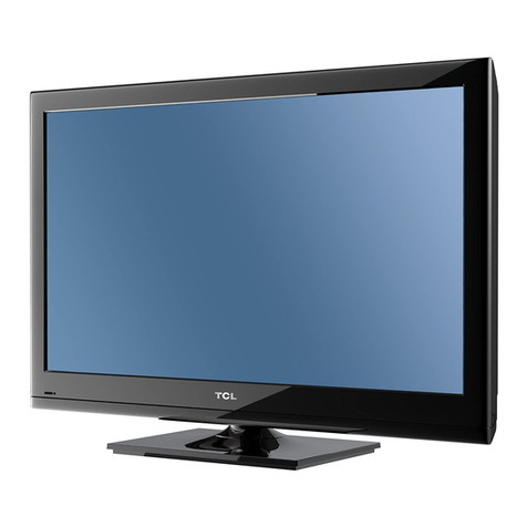
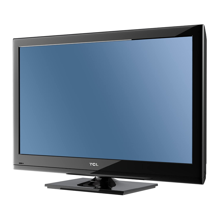
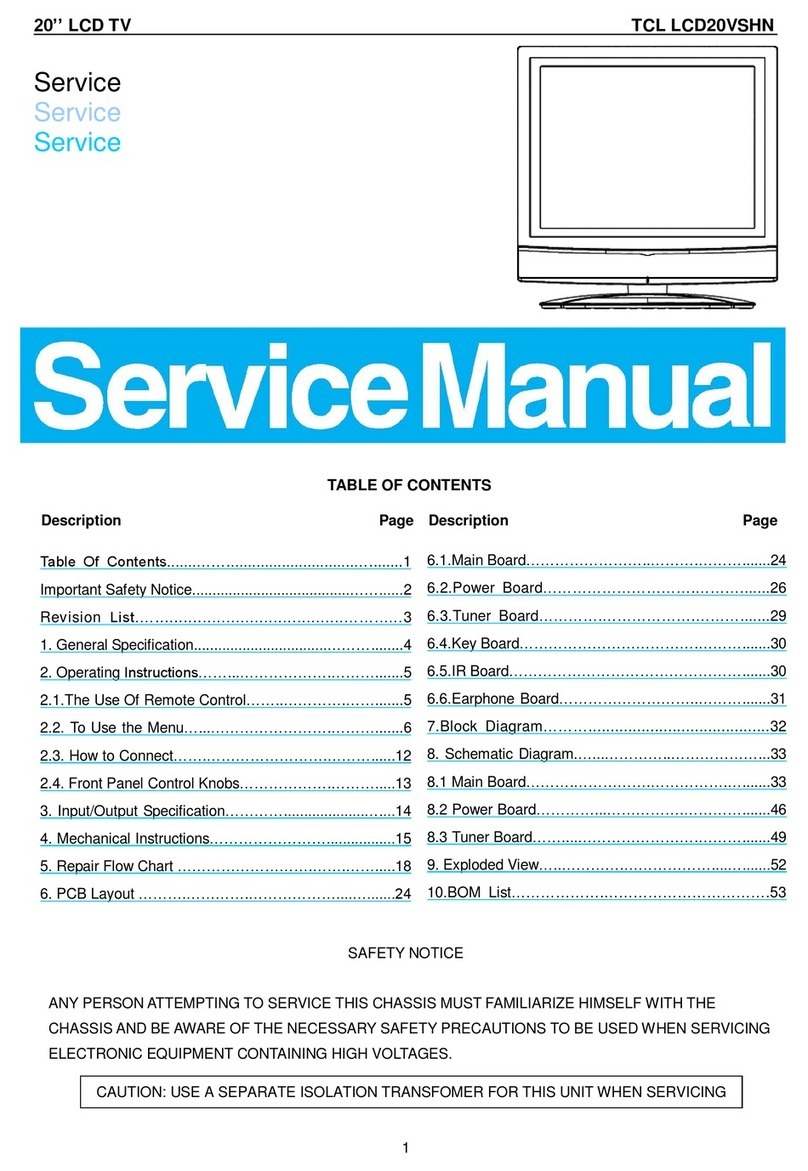
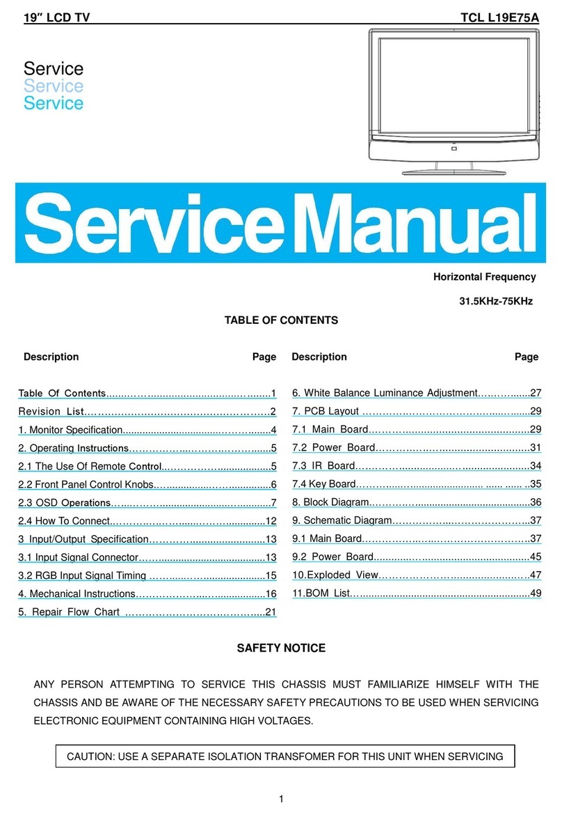
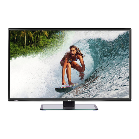
TCL L32B2800 User manual

TCL
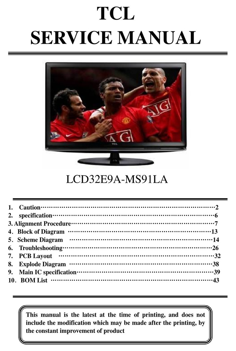
SERVICE MANUAL
L32B0MS08PA-LA
1. CautionĂĂĂĂĂĂĂĂĂĂĂĂĂĂĂĂĂĂĂĂĂĂĂĂĂĂĂĂ2
2. Specification ĂĂĂĂĂĂĂĂĂĂĂĂĂĂĂĂĂĂĂĂĂĂĂĂĂ6
3. Alignment ProcedureĂĂĂĂĂĂĂĂĂĂĂĂĂĂĂĂĂĂĂĂĂĂ7
4. Block Diagram ĂĂĂĂĂĂĂĂĂĂĂĂĂĂĂĂĂĂĂĂĂĂĂĂ2
5. Scheme DiagramĂĂĂĂĂĂĂĂĂĂĂĂĂĂĂĂĂĂĂĂĂĂĂ 2
6. PCB Layout ĂĂĂĂĂĂĂĂĂĂĂĂĂĂĂĂĂĂĂĂĂĂĂĂĂ27
7. Trouble ShootingĂĂĂĂĂĂĂĂĂĂĂĂĂĂĂĂĂĂĂĂĂĂĂĂ
8. Explode DiagramĂĂĂĂĂĂĂĂĂĂĂĂĂĂĂĂĂĂĂĂĂĂĂĂ35
9ˊBOM ListĂĂĂĂĂĂĂĂĂĂĂĂĂĂĂĂĂĂĂĂĂĂĂĂĂĂĂ36
This manual is the latest at the time of printing, and does not
include the modification which may be made after the printing, by
the constant improvement of product

CA UTION: TO RE DUCE THE RIS K OF
ELECTR ICA L SHOCK, DO NOT RE MOVE
COVER (OR BACK). NO USER SERVICEABLE
PAR TS INSIDE . RE FER SER VIC ING TO
QUALIFIE D SERVICE PERSONNEL.
The lighting flash with arrowhead symbol, with an equilateral triangle is intended to
alert the user to the presence of uninsulated voltage within the products
enclosure that may be of sufficient magnitude to constitute a risk of electric shock to
the person.
The exclamation point within an equilateral triangle is intended to alert the user to the
presence of important operating and maintenance (servicing) instructions in the
literature accompanying the appliance.
CAUTION:
Use of controls, adjustments or procedures other than those specified herein may result in
hazardous radiation exposure.
CA U T ION
RISK
RISK OF
ELECTRI
ELECTRIC
SHOCK
SHOCK DO
NOT
NOT
OPEN.
OPEN.
2
dangerous
WARNING: TO REDUCE RISK OF FIRE OR ELECTRIC SHOCK, DO NOT
EXPOSE THIS APPLIANCE TO RAIN OR MOISTURE.
SCHNEIDER ELECTRONICS GMBH-GERMANY
1. CAUTION

1. When the power cord or plug is damaged or frayed, unplug this television set from the wall outlet and refer servicing to
qualified service personnel.
2. Do not overload wall outlets and extension cords as this can result in fire or electric shock.
3. Do not allow anything to rest on or roll over the power cord, and do not place the TV where power cord is subject to
traffic or abuse. This may result in a shock or fire hazard.
4. Do not attempt to service this television set yourself as opening or removing covers may expose you to dangerous
voltage or other hazards. Refer all servicing to qualified service personnel.
5. Never push objects of any kind into this television set through cabinet slots as they may touch dangerous voltage
points or short out parts that could result in a fire or electric shock. Never spill liquid of any kind on the television set.
6. If the television set has been dropped or the cabinet has been damaged, unplug this television set from the wall outlet
and refer servicing to qualified service personnel.
7. If liquid has been spilled into the television set, unplug this television set from the wall outlet and refer servicing to
qualified service personnel.
8. Do not subject your television set to impact of any kind. Be particularly careful not to damage the picture tube surface.
9. Unplug this television set from the wall outlet before cleaning. Do not use liquid cleaners or aerosol cleaners. Use a
damp cloth for cleaning.
10.1. Do not place this television set on an unstable cart, stand, or table. The television set may fall, causing serious injury
to a child or an adult, and serious damage to the appliance. Use only with a cart or stand recommended by the
manufacturer, or sold with the television set. Wall or shelf mounting should follow the manufacturer s instructions, and
should use a mounting kit approved by the manufacturer.
10.2. An appliance and cart combination should be moved with care. Quick stops, excessive force, and uneven surfaces
may cause the appliance and cart combination to overturn.
CAUTION:
Read all of these instructions. Sa ve these instructions for later use . Follo w all W arnings and
Instructions marked on the audio equipment.
1. Read Instructions-All the safety and operating instructionsshouldbe read before the productis operated.
2. Retain Instructions- The safety and operating instructions should be retained for future reference.
3. Heed Warnings- All warnings on the product and in the operating instructions should be adhered to.
4. Follow Instructions- All operating and use instructions should be followed.
3
SCHNEIDER ELECTRONICS GMBH-GERMANY
IMPORTANT SAFETY INSTRUCTIONS
FOR YOUR PERSONAL SAFETY
3

11. Do not use this television set near water ... for example, near a bathtub, washbowl, kitchen sink, or laundry tub, in a
wet basement, or near a swimming pool, etc.
Never expose the set to rain or water. If the set has been exposed to rain or water, unplug the set from the wall
outlet and refer servicing to qualified service personnel.
12. Choose a place where light (artificial or sunlight) does not shine directly on the screen.
13. Avoid dusty places, since piling up of dust inside TV chassis may cause failure of the set when high humidity persists.
14. The set has slots, or openings in the cabinet for ventilation purposes, to provide reliable operation of the receiver, to
protect it from overheating. These openings must not be blocked or covered.
Never cover the slots or openings with cloth or other material.
Never block the bottom ventilation slots of the set by placing it on a bed, sofa, rug, etc.
Never place the set near or over a radiator or heat register.
Never place the set in enclosure, unless proper ventilation is provided.
15.1. If an outside antenna is connected to the television set, be sure the antenna system is grounded so as to provide some
protection against voltage surges and built up static charges, Section 810 of the National Electrical Code, NFPA No.
70-1975, provides information with respect to proper grounding of the mast and supporting structure, grounding of the
lead-in wire to an antenna discharge unit, size of grounding conductors, location of antenna discharge unit, connection
to grounding electrode, and requirements for the grounding electrode.
15.2. Note to CATV system installer : (Only for the television set with CATV reception)
This reminder is provided to call the CATV system attention to Article 820-40 of the NEC that provides
guidelines for proper grounding and, in particular, specifies that the cable ground shall be connected to the grounding
system of the building, as close to the point of cable entry as practical.
16. An outside antenna system should not be located in the vicinity of overhead power lines or other electric lights or power
circuits, or where it can fall into such power lines or circuits. When installing an outside antenna system, extreme care
should be taken to keep from touching such power lines or circuits as contact with them might be fatal.
17. For added protection for this television set during a lightning storm, or when it is left unattended and unused for long
periods of time, unplug it from the wall outlet and disconnect the antenna. This will prevent damage due to lightning
and power-line surges.
ANTENNA
LEAD- IN WIRE
ANTENNA DISCHARGE
UNIT (NEC SECTION
810-20)
GROUNDING
CONDUCTORS
(NEC SECTION810-21)
GROUND CLAMPS
POWER SERVICE GROUNDING
ELECTRODE SYSTEM
(NEC ART 250. PART H)
ELECTRIC SERVICE
EQUIPMENT
GROUND CLAMP
NEC-NATIONAL ELECTRICAL CODE
EXAMPLE OF ANTENNA GROUNDING AS PER
NATIONAL ELECTRICAL CODE
EXAMPLE OF ANTENNA GROUNDING AS PER NATIONAL ELECTRICAL CODE INSTRUCTIONS
a built-in
installer s
4
SCHNEIDER ELECTRONICS GMBH-GERMANY
PROTECTION AND LOCATION OF YOUR SET
4
18.
This television set should be operated only from the type of power source indicated on the marking label.If you are not
sure of the type of power supply at your home, consult your television dealer or local power company. For television
sets designed to operate from battery power, refer to the operating instructions.
19. If the television set does not operate normally by following the operating instructions, unplug this television set from the
wall outlet and refer servicing to qualified service personnel. Adjust only those controls that are covered in the operating
instructions as improper adjustment of other controls may result in damage and will often require extensive work by a
qualified technician to restore the television set to normal operation.
20. When going on a holiday : If your television set is to remain unused for a period of time, for instance, when you go on
a holiday, turn the television set and unplug the television set from the wall outlet.
21. If you are unable to restorenormal operation by followingthe detailedprocedurein your operatinginstructions,
do not attempt any further adjustment. Unplug the set and call your dealer or service technician.
22. Whenever the television set is damaged or fails, or a distinct change in performance indicates a need for
service, unplug the set and have it checked by a professional service technician.
23. It is normal for some TV sets to make occasional snapping or popping sounds, particularly when being
turned on or off. If the snapping or popping is continuous or frequent, unplug the set and consult your
dealer or service technician.
24. Do not use attachments not recommendedby the television set manufacturer as they may cause hazards.
25. When replacementparts are required,be sure the service technicianhas used replacementparts specified
by the manufacturer that have the same characteristics as the original part. Unauthorized substitutions
may result in fire, electric shock, or other hazards.
26. Upon completion of any service or repairs to the television set, ask the service technician to perform
routine safety checks to determine that the television is in safe operating condition.
off
5
SCHNEIDER ELECTRONICS GMBH-GERMANY
OPERATION OF YOUR SET
IF THE SET DOES NOT OPERATE PROPERLY
FOR SERVICE AND MODIFICATION
5

Product Type LCD Smart TV Music MP3/AC3/HE-AAC/LPCM
Chassis MS08PA-LA Picture JPEG/PNG/BMP/MPO
CPU 800MHz
H.264/MPEG2/MPEG4/Motion JPEG
GPU ---
OS Linux
Memory 2Gb DDR3 / 4Gb Nand Flash File ---
OSD Language English/Portuguese/Spanish
PAL M/N,NTSC-M
ISDB-T
Component Video Format YP
B
P
R
:up to 1080P
AV System
PAL,NTSC
DVI Video Format Up to XGA for HDMI-PC
Channels(Analog) Antenna:2~69;CATV:1~125
HDMI Video Format up to 1080P
DTV Channels(Digital) Antenna:7~69
PC Compatibility Up to SXGA
Power Supply
AC 110V-240V 50/60Hz
Power Consumption(TV On)
45W
Power Consumption(Standby)≤0.5W Backlight Unit LED
Certification CB Panel supplier CSOT(ST3151A04-3)
Wired Network Default Aspect Ratio 16:9
Built-in WI-FI Panel Size (inch) 32"
Display Resolution 1366*768
Brightness (cd/m2)(typ.) 250
Contrast Ratio 4000:1
Response Time (G to G) 6.5ms
Auto Source --- Viewing Angle (H/V) 178°/178°
EPG
Yes(at DTV)
Life Time(Typ.) >30,000hrs
Subtitle --- Color 16.7M (8 bit)
Parental Control
Yes (at DTV)
Refresh Rate 60Hz
Content restriction
Yes (at DTV)
Sleep Timer Yes
System Update Yes
Side
Hotel Mode
---
Input Method Smart TV IME
MHL ---
Teletext ---
Nicam ---
Lightsensor ---
3DTV Type ---
3D Format ---
Natura Light Technology Yes (Natural Light Engine ‖)
DCC(Dynamic Contrast Control)ON、Off
Backlight Adjustable Yes (0~100)
Color Temperature Normal/Cold/Warm
Picture Mode Normal、Vivid、Mild、User
Picture Size Auto、16:9、4:3、Just Scan
Gamma Adjustable ---
Comb Filter 3D
Back
Dynamic Noise Reduction 3D
Adaptive Deinterlacing 3D
Motion Compensation
Yes
Speakers Integrated speakers (Bottom side)
Audio Power Output(THD=7%)2×5W
Smart Volume Yes
Smart Audio User、Music、Movie、News、Standard
Sound Control Volume、Balance 、5 Band EQ
Sound Scene ---
Surround Sound ---
DD (Dolby Digital ) Yes
DD+(Dolby digital plus) Yes
Dolby Pulse Yes
Basic Information Media Format
Terminals
Panel Specification
Internet Link
Video
Basic Function
Picture
Sound
PRODUCT SPECIFICATION RELEASE
Model: L32B2800/MS08PA-LA/CS2
Version:1.0 Issued On: 2014-05-06
Signal Format Capability
TV System

YouTube V4
YouTube Leanback
Opera TV Store
compact TV appstore
Facebook
Social Network
Twitter
Social Network
Picasa
Online Album open API
Brazil local
media, authorized API
Opera TV Browser
TV Browser The application is for Brazil
Mechanical Ke
y
S
p
ecification
Carton Dimensions LxWxH(mm)851*136*531mm
Container Loading---20 feet(pcs)472
Container Loading---40 feet(pcs)1004
Container Loading--40 feet High(pcs)1180
Net Weight With Stand(Kg)5.1
Net Weight Without Stand(Kg)---
Gross Weight With Packaging(Kg)6.3
VESA Mounting Dimensions LxH(mm)200x150
Operation Manual Spanish(Default) Wall Mount WMB233
Remote Control and batteries RC199C Wireless Keyboard ---
Base Stand Integrated Packaging
Wireless Mouse ---
AC power cord 1 pc Built-in WI-FI(MT7601) 07-WF75RL-MA0G
Adapt Cable Wire For AV Or YPBPR --- WI-FI DONGLE (AR9271) ---
RF Converter(IECType toType F) ---
Drafted by: Approved by:
Design and specifications are subject to change without notice!
PVR
PVR
(P
ersona
l
Vid
eo
R
ecor
d)
a
ll
ows you
t
o
record your favorite TV programme.
Special FunctionPre-Installed Application List
Picasa Picasa is a software for you to search, edit
and manage photos.
Terra TV
Optional Accessories
Essential Accessories(Default)
Remote ID Picture
Mechanical ID Picture
734.5
480
431.5
15.4
18.
15.
340
80
160
Unit:mm

Factory Test & Alignment Specification For MS08P-LA Series (V1.0)
Page 1 of 9
7CL ,3& R&D CENTER
Factory Test & Alignment Specification
(FTAS)
for MS083-LA Series
Version 1.
PREPARED BY: Hongxin Gao DATE: 2014-04-23
APPROVED BY: DATE:

Factory Test & Alignment Specification For MS08P-LA Series (V1.0)
Page 2 of 9
Disclosure
The information contained in this document is proprietary to TCL IPC R&D CENTER and shall not
be disclosed by the recipient to third persons without the written permission of the team leader
or GM of R&D. Revision History
Version Issue Date Description of changes

Factory Test & Alignment Specification For MS08P-LA Series (V1.0)
Page 3 of 9
These chassis are designed for LatinAmerica(LA) markets ready for IPTV. The main chip is from
Mstar and supports below features matrix:
Class Item MS083-LA
ATV
( PA L M /PAN N / N TSC) Cable & Antenna
DTV
(ISDB-T) Antenna
HDMI
(480i/p, 576i/p, 720p up to 1080i/p, compliant v1.4
with HDCP)
3
CMP
(YPbPr can support from 480i up to 1080p, audio) 1
AV
(CVBS, audio)Share with CMP 1
AV out Share with SPDIF
USB thumb drive
2
- Picture, Video, Audio Playback
- Hub, Mouse, Keyboard rd
Headphone output NO
Inputs
&
Outputs
SPDIF output Coaxial
OAD No
WIFI Yes
DIVX No
DLNA (DMP) Yes
Internet Yes
3D (auto, top & bottom, side by side, frame
sequencing, …)
1920x2205@24Hz (1920x1080p x2)
1280x1470@50Hz (1280x720p x2)
1280x1470@60Hz (1280x720p x2)
Optional
Functions
Audio Return Channel (ARC) Yes
I2C connector of MEMC module N/A
Others Main SW Serial NAND Flash
BIN image
U501
IC Details
&
Position
Main IC
U700
INFO:
ª All tests and measurements mentioned hereafter have to be carried out at a normal mains voltage
(100 ~ 240 VAC)
ª All voltages have to be measured with respect to ground, unless otherwise stated
ª All final tests have to be done on a complete set including LCD panel in a room with temperature of
25+/-7°C
ª The Picture Performance assessment such as White Balance (luminance and colour temperature)

Factory Test & Alignment Specification For MS08P-LA Series (V1.0)
Page 4 of 9
has to be performed into subdued lighted room after at least 45min of warm-up in order to avoid any
temperature drift influence (colorimetry vs time)
1. PCB/SKD Assembly: Test & Alignment
1.1.Pre-Conditions and DC/DC Check
Before powe r-on, please check the board accordi ng to the releva nt block diagram and circuit
diagram, and make sure that no serious issue or mistake can destroy the board. For e xample, the
output of DC/DC and LDO should not be shorted to ground.
Supply a suited voltage and power-on, then check the voltage according to the relevant block
diagram, circuit diagram and voltage spec. The error should less than 5%. For example, the voltage
for main chip (+3V3, AV3.3, +1V2, CORE1V2, etc.), the voltage for DDR (DDRV), the voltage for
amplifier (AMP_VCC), etc...
Position Value Remark
UD90 5V ±5%
UD60 1.15V ±5%
U172/U175 3.3V ±5%
U174 1.5V ±5%
U201 TUNER_3.3V
1.2.SW Image download
(
Developing
)
Download the latest release SW from below PDM system:
- Link: http://sw.tcl-cctv.com
- Username:
- Password:
See Appendix o“How to upgrade FLASH SW using USB”
1.3.Project ID Modification
There a re di fferent ID stored into the NV M depen ding on dif ferent Panels settings and Models
features, but there’s only one key branching Project ID that includes all. So, it’s not recommended to
modify Panel ID with Hyper terminal as other ID features may not change!
To modify Project ID, you need to go through “Design menuÆService menuÆProject ID”, then
spin left or right with RCU “Zoom±” keys to suitable ID (Project name is dynamically refreshed).
See Appendix p“How to change Project ID with RCU”
Here below is none exhaustive Project ID table for reference:
MODEL ProjectID Panel Name
L28B2500 001 LVW320NEAL CJ9W02
L32B2800 002 LVF400NEAL SJ9W00 V6
L40B3800 005 LVF480ND2L CD9W00 V3

Factory Test & Alignment Specification For MS08F1-LA Series (V1.1)
Page 5 of 9
L55S4600F 004 LVF550ND2L CD9W00 V3
1.4.Functional Test
Once the b oards (chas sis, KB, IR, PSU…) an d the p anel are w ell interconnected, plug all
external generator devices to relevant inputs/outputs below according to their respective test patterns
format and check picture content and sound quality accordingly:
Source Test Signal Test Pattern
Analog/Digital Tuner
(VHF/UHF & CATV) RF cable generator
2D - Movie 1280x720
2D - Static Picture 1920x1080
1. Frequency Range: full band
2. Standard: NTSC /PAL M
3. ISDB-T
SPDIF (Coaxial) Audio Amplifier PCM or Dolby D+
AV IN
(CVBS & AUDIO)
Chroma/Fluke
generator PAL Half Color & Gray bars
CMP
(YPbPr & Audio)
Chroma/Quantum Data
generator
1920x1080i@60Hz
Half Color & Gray bars
HDMI
(Video & Audio)
with beyond HDMI 1.3
and HDCP compliant
DVD/BD player
2D - Movie 1280x720i@60Hz
RJ45
(LAN) Internet ICMP packets echo request
Headphone via mini jack adapter RF signal Suitable channel
Loud Speakers / Enclosures RF signal Suitable channel
AV OUT
(Audio) RF signal Suitable channel
Audio tones can be defined by the factory (i.e. 1 KHz & 3 KHz sweep).
Picture video formats can be changed by the factory according to their own standard.
Remark:1. AV Video & Audio in shared with CMP.
1.5.AD Calibration Test
As SoC is built-in an A/D self-calibration mechanism, ADC need not to be performed any more.
1.6.DDC & EDID & T-Link Test
The E-EDID data structures are according to VESA Enhanced EDID 1.3 (and EIA/CEA- 861B for
HDMI). CEA Timing Extension structure has been extended to support all 3D capable timings.
All VGA and HDMI structures have their own BIN profile which are part of main SW and uploaded
at power-on into HDMI switch chipset.
For EDID check, it’ s needed to check whether the correct EDID is down loaded b y checking
corresponding EDID NVM Checksu m or read t hem out to check bit by bit if i t i s in line with the
released EDID bin file.

Factory Test & Alignment Specification For MS08F1-LA Series (V1.1)
Page 6 of 9
1.7.HDCP Test
For HDCP compliancy, it’s needed to check whether the HDCP key has been well set.
1.8. LAN/WLAN Test (MAC address)
MAC Address Upgrade
See Appendix s“How to upgrade MAC Address
2. Product Assembly (PA): Test & Alignment
2.1.Factory Menu
Follow the below steps to pop-up the Factory menu in case of “Factory Key” is disabled:
- Press RCU “MENU” key to display main menu
- Select “Setting” and press “OK” key to enter into setting submenu
- Select “Picture” and press “OK” key to enter into picture submenu
- Scroll down to “Contrast” item
- Press the subsequence RCU keys “9”, “7”, “3” and “5”
In case of “Factory Key” is enabled, just press R CU “Return” key to pop-up again the Factory
menu.
The status of “Factory Key” can be changed in Factory Menu->Hotkey.
Press RCU “OK” key or “RIGHT” key to enter the submenu.
Press RCU “Menu” key to go back to the root menu.
Press RCU “RIGHT” or “LEFT” key to change the values.
Press RCU “OK” key run the function.
Press RCU “Exit” key exit the Factory menu.
See Appendix t“Factory Menu Description”
2.2.Warm-up
Following TCL standard and practices, it’s required minimum 15min of Warm-Up that can be
considered as Burn-In.
Additional Aging for White Balance alignment is no more necessary due to consistent Picture
Performance with Cloning usage.
This function is accessible by selectin g “Factory menu ÆWARM-UP”, pressing RCU “ Zoom+”
key and then leaving Factory menu . Other faster methods are availa ble on above enclosed
SIACP requirements (rev. v3.9).
2.3.White Balance (WB)
(
Developing
)
¾ for Alignment: ± 0.003
¾ for Measurement: ± 0.01
2.4.SHOP-END initial

Factory Test & Alignment Specification For MS08F1-LA Series (V1.1)
Page 7 of 9
At final process st age, it’ s necessary to perform “Reset shop” before any p acking to lea ve
Factory mode and restore User default presets.
This function is accessible by selectin g “Factory menu ÆSHOP init”, then pressing RCU “OK”
key. Other faster methods are available on above enclosed SIACP requirements (rev. v3.9).
Appendix n“How to upgrade SW FLASH using Mstar tool” (Developing)
Appendix o“How to upgrade FLASH SW using USB”
¾ Copy the SW BIN image “MstarUpgrade.bin” into USB stick root path.
Note: If there’s already other “MstarUpgrade.bin” into USB root, it needs to be deleted or renamed.
¾ Plug USB stick to the TV USB slot.
¾ Pres s RCU MENUÆSettingÆSoftware upgradeÆBy USBÆConfirm.
Or, turn of f the TV press and hold th e power key of key boar d before r econnect AC cord to
restart TV for 5-8seconds (Forced Upgrade).
¾ When the "UPGRADING SOFTW ARE" picture appears as below , it means TV is uploading
SW BIN image. Waiting a few minutes.
¾ When updating is successful, TV should restart automatically.
Appendix p“How to change Project ID with RCU”
¾ Process following subsequence IR codes to change pro ject ID: 062598+MENU+xxx (xxx:
Project ID, ex: 003) with TV automatic restart.
Appendix q“How to upgrade MAC Address
¾ Upgrading MAC address need to use the tool in factory and through serial command, the
specific methods according to the operation of the factory guidance.
Appendix r“Factory Menu Description”
1- Factory hotkey submenu
Item Sub-item Value Note
Factory
hotkey Of f/On OFF:hotkey is invalid
ON :hotkey(Return key) is availability

Factory Test & Alignment Specification For MS08F1-LA Series (V1.1)
Page 8 of 9
2- Warm-Up Mode submenu
Item Sub-item Value Note
Warm-UP
Mode Of f/On
Select panel On with left/right key, Press
“EXIT” key to enter the burning mode;
Press “Menu” key on keyboard t o exit the
burning mode
3-ADC submenu
As SoC is built-in an A/D self-calibration mechanism, ADC need not to be performed any more.
4-White Balance submenu
Item Sub-item Value Note
Source HDMI, etc Balance source are:
HDMI, ATV,DTV, PAL, NTSC, CMP
Color Temp Normal
/Warm/Cool
Warm and cool value is relative to Normal
one. Normal is the default Tone mode
R Gain 000..255 R White balance (-127..+128 for gain)
G Gain 000..255 G White balance (-127..+128 for gain)
B Gain 000..255 B White balance (-127..+128 for gain)
R Offset 000..255 R G ray balance (-127..+128 for offset)
G Offset 000..255 G G ray balance (-127..+128 for offset)
B Offset 000..255 B G ray balance (-127..+128 for offset)
White Balance Init DO Press “OK” key t o i nitial t he preset R GB
Gain/Offset value
VGA ADC Status NG
White
Balance
YPbPr ADC Status NG
5-Shop init submenu
Item Sub-item Value Note
Shop Init DO
Clear date o f N VM in us er me nu,include
the v alue r elated i nstallation,and Cle ar
date of fa ctory menu except the i tem o f
Balance and sound ,set to default value
6-NVM Reset submenu
Item Sub-item Value Note
Reset
ALL DO
Clear N VM v alues ,and s et t o default
value
7-Power On Mode submenu

Factory Test & Alignment Specification For MS08F1-LA Series (V1.1)
Page 9 of 9
Item Sub-item Value Note
Power
On Mode ON/LAST/ST B
ON: The s et will power on after switching
on power
STB: Force TV to start in standby
Last: F orce T V t o st art f rom last power
status
8-USB UPDATE submenu
Item Sub-item Value Note
Main Upgrade Upgrade software
MEMC Upgrade Upgrade MEMC
HDCP Uprade Upgrade HDCP
Mboot upgrade Upgrade Mboot
NVM Upgrade Upgrade NVM
NVM backup Backup NVM
CH list Upgrade Upgrade CH list
USB
UPDATE
CH list backup Backup CH list
9-Device ID test submenu
Item Sub-item Value Note
USB Clone Mode
All
Channel List
EEPROM
User Setting
Select to c hoose th e th ings y ou want to
clone
TV TO USB DO Press “R ight” key to c opy the d ata(WB,
ADC, picture setting, etc) to USB
USB
Clone
USB TO TV DO Press “Right” key to set the data(WB,
ADC, picture setting) from USB
Appendix s“Instructions of Updating SW”
1. The following IC should be pre-copied before SMT process
Position PART TYPE Part Number SW
U501 IC-TSOP48 13-FHMT29-4GB(CPP) Mboot, Main Software
2. The MAC Address, HDCPKEY, Device ID must be upgrade by debug port into U501.

GND
T
T
T
T
T
T
GND
GND
GND
GND
GND/ADJ
OUT
VIN
4
T
GND GND
T
T
T
GND
GND
GND
GND
OUT
AGND
FB
EN
PGND
SW
VIN
PG
GND
GND
T
...
DD-MM
DD-MM
DD-MM
DD-MM
...
...
...
...
...
...
...
...
...
...........
... ... ...
...
...
...
DD-MM-YY
......
Tel +86-755-3331xxxx Fax +86-755-3331xxxx
Nanshan District, Shenzhen, Guangdong
B Building, TCL Tower, Nanhai Road
TCL Thomson Electronics Ltd.
OF :
PAGE:
ON:
BY:
BY:
ON: CHECKED
DATE
Last saved :DESCRIPTION Last modifNAME
A
321
F
E
D
C
B
8 7 6 5
5
4 3 2 1
THIS DRAWING CANNOT BE COMMUNICATED TO UNAUTHORIZED PERSONS COPIED UNLES S PERMITTED IN WRITING
F
E
D
C
B
A
4678
FORMAT DIN A2
Index-Lab DESIGNATION
SBU :
TCLNO:
DRAWN
GND
GND
T
GND
GND
GND
GND
GND
VIN
FB
SS
EN
FSW
GND
BST
LX
COMP
GND
GND
GND
GND/ADJ
OUT
VIN
4
T
VOUTVIN ADJ/GND
D2
D1
G
S2
S3
D4
D3
S1
GND
GND
GND
LO =>Panel OFF
GND
KEY1
NC
R165/C157 CLOSE TO IC
C198 CLOSE TO connect
NC
R-LED
GND
IR
Vref=0.6V
(Vin=2.5V-5.5V)
@max3A
Fixed OCP=4.2A
If Vout=1V Set RD61=150K RD62=4.7K RD63=220K
If Vout=1.2V Set RD61=150K RD62=0R RD63=150K
If Vout=1.5V Set RD61=150K RD62=8.2K RD63=91K
If Vout=1.8V Set RD61=150K RD62=6.2K RD63=68K
If Vout=5V Set RD95=27K RD96=5.1K RD91=100K CD97 /CD98=22uF/10V(NO:28-CA0226-MBX ) And CD99 NC And LD90=4.7UH(NO:33-YLL479-MTX)
Output 1.5076V=1.25*(1+68/330)
@max4A
BOM COST=2.35RMB
If Input Voltage=24V,CD90/CD91=2.2uF/50V
If Vout=12V Set RD95=51K RD96=3.6K RD91=68K CD97 /CD98/CD99=10uF/16V
Change RD90 to adjust Fsw, Set Fsw=600kHZ
(Vin=3V-36V)
Fixed OCP=5.5A
Vref=0.8V
If Input Voltage=12V,CD90/CD91=10uF/16V(NO:28-CC0106-KBX) RD93=22K
3_3VSB
3_3VSB
SWITCH POWER
HI =>Panel ON
Fixed Fsw=1.2MHZ
For timing sequence
BOM COST=1.22RMB
C107
470P
R110
10R
DD91
SK54
C65
0.1U
CD60
0.1U
1
2
3
4
5
P104
1
2
3
4
P103
R105
220R
CD99
10U
7
8
4
2
3
5
6
1Q101
PMK50XP
23
1
U174 AZ1117
DIM_OUT
B
C
E
Q102
BT3904
5V
3_3VSB
R102
33K
R119
0R
3_3V
3_3V
RD62
39K
CD93 NC/220P
NC/0.1U
C172
C171
10U
16V
NC/100U
C174
1_5V
C181 10U
12V
5VSTB
RD93
22K
CD90
10U
CD91
10U
1
2
3
4
U172
AS1117-3.3
RD91
33K
C175 10U
5V
C176 0.1U
RD92
100K
9
6
7
8
4
3
2
1
5
UD90
AOZ1284PI
RD90
82K
CD96
0.1U
CD95
0.047U
DD90
SR34NC/
RD94
10R
CD9A 0.1U
CD94
1000P
CD92
0.1U
C185 10U
1V5
R171
330R
C182 0.1U
C177
10U
R172
68R
2
40-MS39A0-MAA2HG
3-11-2014_10:05 9
RD95
27K
RD96
5K1
CD97
22U CD98
22U
LD90
4.7UH
VCCK
CD62
22U CD63
22U
CD61
10U
5V
LD60
1UH VCCK
5
6
7
8
4
3
2
1
UD60
MP2143 CD64
10U
120K
RD63
RD61
150K
RD60
510K
R121
2K2
BL_ON_OUT
R122
330R
C103
0.01UR103
10K
C106
0.01U
C102
0.01U
DIM_PWM
BL_ON
POWER_ON
R104
330R
POWER_ON_OUT POWER_ON
BL_ON
BL_ON_OUT
3_3VSB
3_3VSB
C112
10U
C114
22U
C110
10U
3_3VSB
4
1
2
3
U175
AS1117-3.3
5VSTB
C111
0.1U 0.1U
C113
GND GND GND
R163
1K
3_3VSB
3_3VSB
0.1U
C157
R165
22K
R164
47K
LED
LED_OUT
0.1U
C173
0.1U
C154
R109
220R
KEY
C153
1000P
IR
1
3
2
D100 0BAV99NC/
F103
GND
KEY_IN
3_3VSB
IR
KEY_IN
LED_OUT
KEY
IR_IN
GND
5VSTB
5V
C115
0.1U
0.1U C116
R127
2K7
R126
3K3
R125
4K7
R124
33K
POWER_ON
5V
DIM_OUT DIM_PWM

GND
GND
GND
T
GND
GND
GND
GND
T
T
GND
T
T
T
T
GND
GND
GND/ADJ
OUT
VIN
4
IF-
SDA
SCL
IF+
NC3
NC1
VCC
RF_SW
NC2
IF-AGC
NC4
Close to tunter close to SOC
Close to MSTAR SOC
When tuner is 18723,CT70&CT71 0R
The impedance Zi between FAT+ & FAT- should be >=1K
The total capacitance should be <=40PF
Close to SOC
Close to tunter
6
11
10
7
8
1
3
2
4
5
9
TU101
1
2
3
4
U201
AZ1117
R205
1K
TU1_VCC
5V
0.1U
C216C215
0.1U
C214
10U
10V
C217
220U
6.3V
C207
0.022U
R207
0R
R208
10K
3_3V
IF-AGC
TU_VCC
T_SDA
RF_SW R206
470R
C203 10U
R204
4K7
R203
4K7
AGC
R202
33R
C206
6800P
R201
33R
C201
22P
C202
22P
C205
22P
C204
22P
T_SDA
IF+
IF-
TU1_VCC
TU1_SCL
RF_SW
IF_AGC
TU1_SDA
T_SDA
T_SCL
TUNER_FAT+
TUNER_FAT-
TUNER_AGC
TU1_VCC
C209 0.1U
C210 0.1U
C212
20P/NC
NC/47P
C213
C218
0.1U
C219
0.1U
NC/47P
C211
R209
NC/200R
TUNER_FAT-
TUNER_FAT+ FAT+_D
FAT-_D

GND
T
TTTT T
GND
GND
GND
GND
L
CVBS
GND
R
TT
GND
GND
GND
T
T
TTT
GND
T
T
T
T
GND
GND
GND
GND GND
GND
GND
GND
GND
GND
T
T
T
GND
TT
GND
MNT-HOLE1
MNT-HOLE2
T
GND
GND
GND
VIN
EN/EN# NC
GND
VOUT
GND
GND
BLUE
RED
GREEN
WHITE
RED
BLACK
CLOSE TO SOC
AV Output
IPTV IN WLAN CONNECTOR
ETHERNET
Must be differential 100ohm
close to conn.
close to U300
close to SOC
close to SOC
NEARLY CONNECTOR
NEARLY IC
SPDIF
USB CONNECTOR
AV1/YPBPR IN
C300
220U
16V
1
2
P310
1
2
3
4
P302
1
2
3
4
5
6
P301
5
4 3
2
1
U301/NC
RT9711A
75R/NC
R371 75R/NC
R370
F314
R306
0R/1206
C354
10U/NC
R366
470R/NC
R368
12K/NC
R367
470R/NC
R364
0R
C321/NC
10U
R363
0R
CVBS_OUT
AVOUT1_V
AVOUT1_V
R327
NC/4K7
R326
NC/4K7
R352
100R
R351
100R
USB1_D+_IN
USB1_D-_IN
U0RX
U0TX
R323
75R
C325
1000P
R321
75R
GND_AV_IN
C320
NC/47P
10
11
1
4
3
2
5
6
7
8
9P304
R382 2R2
R381 2R2
C319
0.1U C322
0.1U
RXVN_1
TXVP_0
TXVN_0
RXVP_1
C389 560P
R389 12K
C390 560P
10U
C329 F321
R362
120R
R361
220R
C352
33P
C351
0.1U
R315
33R C303
0.047U
R_IN
L_IN
AV/YPBPR_R_IN
AV/YPBPR_L_IN
C301 2U2
R305 10K
F306
VCOM0
AV1_V_IN
HD1_Y_IN-
HD1_PR_IN
HD1_PB_IN
C343
0.047U
HD1_SOG_IN
HD1_PB
HD1_PR
F313
R346
47R
C344
0.047U
R344
47R
R348
75R
R347
75R
AV1/Y
C330
0.047U
R357
68R
R343
68R C341
0.047U
R342
75R
R341
10R C345
1000P
0.047U
C340
R345
47R
R322
75R
F312F311F310
F309F308
F307
1
2
3
4
5
6
7
8 9
10
11
12
13
14
15
16
U300
TS8121CLF
HD1_Y_IN
5V
3_3VSB
75R
R320 NET_TXC
R338/NC
4K7
C302 2U2
R304 10K
R390 12K
NET_TX1P
NET_TX1N
NET_RX1P
NET_RX1N
F322
F323 SPDIF
GND12
SPDIF_OUT
F4
D-
GND
F3F2F1
D+RXDTXD
NET_RXC
AVOUT_R AVOUT_L R335
220K
C313
1000P
C315
2U2
C314
2U2
C332
1000P
R301
220K
F304
F305
AVOUT1_V
DGND
F302
F303
F301 AVOUT1_R_OUT
AVOUT1_L_OUT
5
4
1
3
2
P311
1U/NC
C353
L310
220R/NC
5V
B
E
C
Q301/NC
BT3906
B
C
E
BT3904
Q302/NC
AVOUT1_V
75R
R365
75R
R369/NC
3
4
5
6
7
8
1
2
9
10
11
12
P400
RX1N
TXC
RX1P
TX1N
TX1P
RXC NET_RXC
NET_RX1N
NET_TXC
NET_RX1P
NET_TX1N
NET_TX1P

GND
GND
T
T
T
T
T
T
T
T
TT
GND
GND
GND
GND
GND
GND
GND
GND
GND
GND
GND
RX2+
GND1
RX2-
RX1+
GND2
RX1-
RX0+
GND3
RX0-
RXC+
GND4
RXC-
NC1
NC2
DDCCLK
DDCDA
GND5
VCC
HPD
RX2+
GND1
RX2-
RX1+
GND2
RX1-
RX0+
GND3
RX0-
RXC+
GND4
RXC-
NC1
NC2
DDCCLK
DDCDA
GND5
VCC
HPD
RX2+
GND1
RX2-
RX1+
GND2
RX1-
RX0+
GND3
RX0-
RXC+
GND4
RXC-
NC1
NC2
DDCCLK
DDCDA
GND5
VCC
HPD
FAULTEN/EN#
GND
VIN
ILIM
VOUT
GND
GND
GND GND
close to Mstar IC
(6)
(6)
(6)
(6)
(6)
(6)
close to Mstar IC
R444
33R
C402
220U
16V
F423
F422
F421
F405
F404
F403
F402
F401
VGA_SCL
R448
510R
C414 0.047U
C412 0.047U
VGA_TXD
R442
18K
43
2
1
5
6
U401
RT9728B
R438
0R
R440
NC/100R
R441 1K
MHL_EN
MHL_CABLE_DET
R439
NC/10K
1 2
3
D401
BAT54C
5V
H2_5V
HDMI2_SDA
HDMI3_SCL
H3_RX2+
C405
10U
C407
0.1U
C406
0.1U
R406
0R
R431
10K
R430
4K7
C404
0.1U
C403
10U
H_CEC
H_CEC
H_CEC
H3_SDA
H3_SCL
H3_HPD
F420
F419
F418
F417
F416
H3_HPD_OUT B
C
EBT3904
Q403
R414
4K7
R413
10K
R412
1K
R411 100R
R410 100R R409 47K
R408 47K
H3_5V
H3_SDA
H3_SCL
H3_RXC-
H3_RXC+
H3_RX0-
H3_RX1-
H3_RX1+
H3_RX2-
15
16
2
5
8
11
17
19
13
14
7
9
4
6
1
3
10
12
18
P801
15
16
2
5
8
11
17
19
13
14
7
9
4
6
1
3
10
12
18
P802
AVDD5V_MHL
R459
33R
H2_HPD_OUT H2_HPD
C410
2U2
H1_ARC
R407
1K
R416 100R
R415 100R
R404
100R
R417 47K
R429 47K
H2_5V
R434
5R6
15
16
2
5
8
11
17
19
13
14
7
9
4
6
1
3
10
12
18
P800
H1_HPD
H1_RXC-
H1_RXC+
H1_RX0-
H1_RX0+
H1_RX1-
H1_RX1+
H1_RX2-
H1_RX2+
H_CEC
H_CEC
CEC
F403
C401
0.047U
R436
300K
R435
100R MHL_CABLE_DET
MHL_DETECT
H2_5V
R433 100R
R432 100R
H2_RX2+
H2_RX0+
H2_RX1-
H2_RX2-
H2_RX1+
H2_RX0-
H2_RXC+
H2_RXC-
MHL_DETECT
F406
F407
F408
F409
F410 F415
F414
F413
F412
F411 H2_HPD
H1_HPD
H1_5V
H1_SDA
H1_SCL
H1_SCL
H1_HPD_OUT
HDMI1_SDA
HDMI1_SCL H1_SDA
B
C
EBT3904
Q402
R425
4K7
R424
10K
H1_ARC_OUT
H1_ARC
H2_5V
H2_SDA
H2_SCL
HDMI2_SCL
H2_SCL
H2_SDA
H1_5V
H3_HPD
H3_RX0+
H_CEC
H3_5V
HDMI3_SDA
H2_5V
5V
VGA_BLU
VGA_HS
R447
33R
75R
R450
R449
75R
R451
75R
10K
R452
R453
10K
C413 0.047U
C411 0.047U
510R
R446
R443
33R
17
16
2
1
9
10
3
13
5
8
12
7
15
14
11
4
6
P405
VGA_VS_IN
VGA_GRN_IN
VGA_SOG_IN
VGA_HS_IN
VGA_BLU_IN
VGA_RED_IN
VGA_VS
VGA_RXD
VGA_RED
VGA_GRN
VGA_SCL
VGA_SDA
VGA_TXD
GND
F424
C419 100P
NC
C418
100P NC
U0RX
U0TX
R454 100R
R457 100R
R455 100R
R456 100R
VGA_BLU
VGA_RXD
VGA_BLU
VGA_VS
VGA_RXD
VGA_GRN
VGA_HS
VGA_RED
VGA_SDA
VGA_VS
VGA_RED
VGA_HS
VGA_SCL
VGA_SDA
VGA_SCL
VGA_VS_IN
VGA_HS_IN
U0TXVGA_SDA
U0RX
VGA_RXD
VGA_TXD
VGA_TXD
VGA_GRN
R445
33R
Table of contents
Other TCL LCD TV manuals