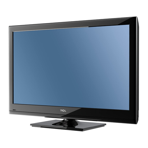
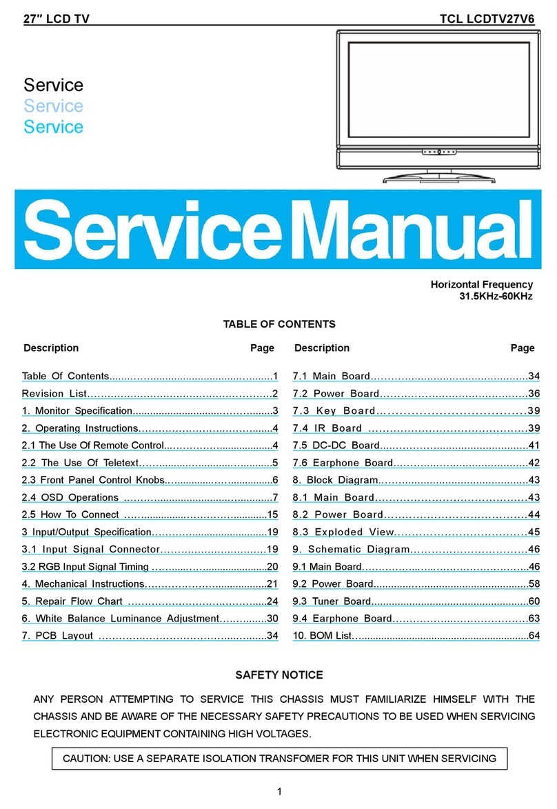
TCL 32E320 User manual

TCL
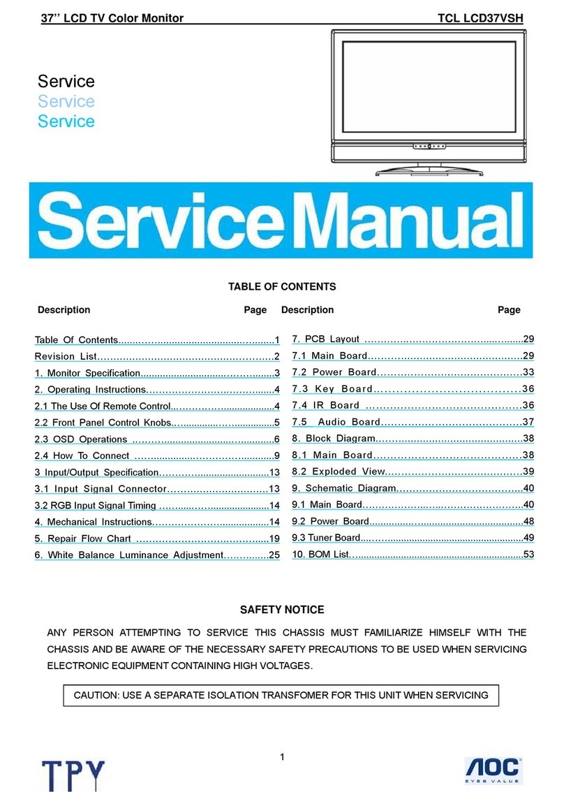
SERVICE MANUAL
32E320 MT23L-LA
1. Caution…………………………………………………………………………2
2. Specification …………………………………………………………………6
3. Alignment Procedure…………………………………………………………7
4. Scheme Diagram…………………………………………………………… 19
5. PCB Layout …………………………………………………………………26
6. Explode Diagram……………………………………………………………30
7.BOM List………………………………………………………………………31
This manual is the latest at the time of printing, and does not
include the modification which may be made after the printing, by
the constant improvement of product

CA UTION: TO RE DUCE THE RIS K OF
ELECTR ICA L SHOCK, DO NOT RE MOVE
COVER (OR BACK). NO USER SERVICEABLE
PAR TS INS IDE . RE FER SER VIC ING TO
QUALIFIE D SERVICE PERSONNEL.
The lighting flash with arrowhead symbol, with an equilateral triangle is intended to
alert the user to the presence of uninsulated voltage within the products
enclosure that may be of sufficient magnitude to constitute a risk of electric shock to
the person.
The exclamation point within an equilateral triangle is intended to alert the user to the
presence of important operating and maintenance (servicing) instructions in the
literature accompanying the appliance.
CAUTION:
Use of controls, adjustments or procedures other than those specified herein may result in
hazardous radiation exposure.
CA U T ION
RISK
RISK OF
ELECTRI
ELECTRIC
SHOCK
SHOCK DO
NOT
NOT
OPEN.
OPEN.
2
dangerous
WARNING: TO REDUCE RISK OF FIRE OR ELECTRIC SHOCK, DO NOT
EXPOSE THIS APPLIANCE TO RAIN OR MOISTURE.
SCHNEIDER ELECTRONICS GMBH-GERMANY
1. CAUTION
2

1. When the power cord or plug is damaged or frayed, unplug this television set from the wall outlet and refer servicing to
qualified service personnel.
2. Do not overload wall outlets and extension cords as this can result in fire or electric shock.
3. Do not allow anything to rest on or roll over the power cord, and do not place the TV where power cord is subject to
traffic or abuse. This may result in a shock or fire hazard.
4. Do not attempt to service this television set yourself as opening or removing covers may expose you to dangerous
voltage or other hazards. Refer all servicing to qualified service personnel.
5. Never push objects of any kind into this television set through cabinet slots as they may touch dangerous voltage
points or short out parts that could result in a fire or electric shock. Never spill liquid of any kind on the television set.
6. If the television set has been dropped or the cabinet has been damaged, unplug this television set from the wall outlet
and refer servicing to qualified service personnel.
7. If liquid has been spilled into the television set, unplug this television set from the wall outlet and refer servicing to
qualified service personnel.
8. Do not subject your television set to impact of any kind. Be particularly careful not to damage the picture tube surface.
9. Unplug this television set from the wall outlet before cleaning. Do not use liquid cleaners or aerosol cleaners. Use a
damp cloth for cleaning.
10.1. Do not place this television set on an unstable cart, stand, or table. The television set may fall, causing serious injury
to a child or an adult, and serious damage to the appliance. Use only with a cart or stand recommended by the
manufacturer, or sold with the television set. Wall or shelf mounting should follow the manufacturer s instructions, and
should use a mounting kit approved by the manufacturer.
10.2. An appliance and cart combination should be moved with care. Quick stops, excessive force, and uneven surfaces
may cause the appliance and cart combination to overturn.
CAUTION:
Read all of these instructions. Sa ve these instructions for later use . Follo w all Warnings and
Instructions marked on the audio equipment.
1. Read Instructions-All the safety and operating instructionsshouldbe read before the productis operated.
2. Retain Instructions- The safety and operating instructions should be retained for future reference.
3. Heed Warnings- All warnings on the product and in the operating instructions should be adhered to.
4. Follow Instructions- All operating and use instructions should be followed.
3
SCHNEIDER ELECTRONICS GMBH-GERMANY
IMPORTANT SAFETY INSTRUCTIONS
FOR YOUR PERSONAL SAFETY
3

11. Do not use this television set near water ... for example, near a bathtub, washbowl, kitchen sink, or laundry tub, in a
wet basement, or near a swimming pool, etc.
Never expose the set to rain or water. If the set has been exposed to rain or water, unplug the set from the wall
outlet and refer servicing to qualified service personnel.
12. Choose a place where light (artificial or sunlight) does not shine directly on the screen.
13. Avoid dusty places, since piling up of dust inside TV chassis may cause failure of the set when high humidity persists.
14. The set has slots, or openings in the cabinet for ventilation purposes, to provide reliable operation of the receiver, to
protect it from overheating. These openings must not be blocked or covered.
Never cover the slots or openings with cloth or other material.
Never block the bottom ventilation slots of the set by placing it on a bed, sofa, rug, etc.
Never place the set near or over a radiator or heat register.
Never place the set in enclosure, unless proper ventilation is provided.
15.1. If an outside antenna is connected to the television set, be sure the antenna system is grounded so as to provide some
protection against voltage surges and built up static charges, Section 810 of the National Electrical Code, NFPA No.
70-1975, provides information with respect to proper grounding of the mast and supporting structure, grounding of the
lead-in wire to an antenna discharge unit, size of grounding conductors, location of antenna discharge unit, connection
to grounding electrode, and requirements for the grounding electrode.
15.2. Note to CATV system installer : (Only for the television set with CATV reception)
This reminder is provided to call the CATV system attention to Article 820-40 of the NEC that provides
guidelines for proper grounding and, in particular, specifies that the cable ground shall be connected to the grounding
system of the building, as close to the point of cable entry as practical.
16. An outside antenna system should not be located in the vicinity of overhead power lines or other electric lights or power
circuits, or where it can fall into such power lines or circuits. When installing an outside antenna system, extreme care
should be taken to keep from touching such power lines or circuits as contact with them might be fatal.
17. For added protection for this television set during a lightning storm, or when it is left unattended and unused for long
periods of time, unplug it from the wall outlet and disconnect the antenna. This will prevent damage due to lightning
and power-line surges.
ANTENNA
LEAD- IN WIRE
ANTENNA DISCHARGE
UNIT (NEC SECTION
810-20)
GROUNDING
CONDUCTORS
(NEC SECTION810-21)
GROUND CLAMPS
POWER SERVICE GROUNDING
ELECTRODE SYSTEM
(NEC ART 250. PART H)
ELECTRIC SERVICE
EQUIPMENT
GROUND CLAMP
NEC-NATIONAL ELECTRICAL CODE
EXAMPLE OF ANTENNA GROUNDING AS PER
NATIONAL ELECTRICAL CODE
EXAMPLE OF ANTENNA GROUNDING AS PER NATIONAL ELECTRICAL CODE INSTRUCTIONS
a built-in
installer s
4
SCHNEIDER ELECTRONICS GMBH-GERMANY
PROTECTION AND LOCATION OF YOUR SET
4
18.
This television set should be operated only from the type of power source indicated on the marking label.If you are not
sure of the type of power supply at your home, consult your television dealer or local power company. For television
sets designed to operate from battery power, refer to the operating instructions.
19. If the television set does not operate normally by following the operating instructions, unplug this television set from the
wall outlet and refer servicing to qualified service personnel. Adjust only those controls that are covered in the operating
instructions as improper adjustment of other controls may result in damage and will often require extensive work by a
qualified technician to restore the television set to normal operation.
20. When going on a holiday : If your television set is to remain unused for a period of time, for instance, when you go on
a holiday, turn the television set and unplug the television set from the wall outlet.
21. If you are unable to restorenormal operation by followingthe detailedprocedurein your operatinginstructions,
do not attempt any further adjustment. Unplug the set and call your dealer or service technician.
22. Whenever the television set is damaged or fails, or a distinct change in performance indicates a need for
service, unplug the set and have it checked by a professional service technician.
23. It is normal for some TV sets to make occasional snapping or popping sounds, particularly when being
turned on or off. If the snapping or popping is continuous or frequent, unplug the set and consult your
dealer or service technician.
24. Do not use attachments not recommendedby the television set manufacturer as they may cause hazards.
25. When replacementparts are required, be sure the service technicianhas used replacementparts specified
by the manufacturer that have the same characteristics as the original part. Unauthorized substitutions
may result in fire, electric shock, or other hazards.
26. Upon completion of any service or repairs to the television set, ask the service technician to perform
routine safety checks to determine that the television is in safe operating condition.
off
5
SCHNEIDER ELECTRONICS GMBH-GERMANY
OPERATION OF YOUR SET
IF THE SET DOES NOT OPERATE PROPERLY
FOR SERVICE AND MODIFICATION
5

EM BUSINESS CENTER
FTV PRODUCT MANAGEMENT DEPT.
SPECIFICATION RELEASE
Version: V1.0 Issued Date: 2011.2.28
PICTURE
Category LCDTV
Naturalight Technology
Yes (Natural Light Engine‖)
Dynamic Contrast Yes
Color Temperature Warm / Normal / Cool SIGNAL FORMAT CAPABILITY
Backlight Adjustable Yes Component Video Format Y,Pb/Cb,Pr/Cr:up to 1080P
Scale Mode Full, Wide Screen,Subtitle,4:3 DVI Video Format Up to XGA for HDMI-PC
Picture Effect User, Bright, Standard and Soft HDMI Video Format up to 1080P
Film Mode (3:2 pull down) AUTO PC Compatibility Up to SXGA
TERMINALS
Audio/CVBS Input (Composite) 2 R/L+2 Video: AV1, AV2(Side)
S-Video Input --
Audio Input for S-Video --
Comb Filter 3D YPbPr Input 1
Dynamic Noise Reduction 3D for SDTV Audio Input for YPbPr 1
Adaptive Deinterlacing 3D for SDTV YCbCr Input Share with "YPbPr"
Blue Stretch Yes Audio Input for YCbCr Share with Audio for "YPbPr"
Black Stretch Yes VGA Input(RGB) 1 (D-Sub,15 Pins)
Motion Compensation Yes Audio Input for RGB Share with Audio for "YPbPr"
DLTI Yes DVI --
DCTI Yes Audio Input for DVI --
Dynamic Skin Correction Yes HDMI 1
Audio/CVBS Output (Composite) 1 (R/L+CVBS) (RCA)
PANEL SPECIFICATION SPDIF Output --
Back light Unit CCFL Headphone Output --
Panel supplier SEC RF Input(Antenna) 1 (IEC Type)
Aspect Ratio 16:9 USB 1
Panel Size (inch) 32.0" BASIC INFO.
Display Resolution 1366*768 TV System NTSC-M;PAL-M;PAL-N
Brightness (cd/m2) 450 AV System PAL,NTSC
Contrast Ratio 4000:1 Channels
Cable 125 (1~125) , Antenna 68 (2~69)
Response Time Tr/Tf 8ms Chassis MT23L-LA
Viewing Angle (H/V) 178°/178° Certification CB
LED Life Time
50,000hrs(Min.)Power Supply AC 100V-240V 50/60Hz
Color 16.7M Power Consumption-TV on 110W
SOUND Power Consumption-Standby
≤1W
Speakers Integrated speakers (Bottom side) Default Color of Front Cabinet Black
Audio Power Output 2×10W Keyboard Position Side
Smart Volume Yes Base Stand Detachable Yes
Sound Effect Standard,News,Movie,User Unpackaged Dimension for Main Body (L*H*D) (mm)
Sound Control Volume, Balance, Bass,Treble, With Base Stand (mm) 785.4Lx590.3Hx196.0D
Without Base Stand (mm) 785.4Lx523.9Hx86.0D
Packaged Dimension (L*H*D)
Main Body (mm) 884(L)x193(W)659(H)
Speaker Box --
FUNCTION Base Stand Packaged with Main Body
OSD Language English/French/Spanish Net Weight (Kg) 10.0KG
OSD Main-Menu Features Motion Bmp style Gross Weight (Kg) 12.06KG
CC (Closed Caption)
Yes (CC1~CC4,TT1~TT4) Container Loading
Sleep Time Select Yes 20 feet (12x6+2x3)x3=234
Watch Time Limit Yes 40 feet (12x13+2x2)x3=480
Listen Only Yes (Listening to Music without picture) 40 feet high (12x13+2x2)x4-1=639
Demo Function Yes ACCESSORIES
DNR Yes Operation Manual English(Default)
Nicam Yes(MTS) Remote Control For TV control (with two batteries)
USB Connection
Yes.(Only for mp3 Player and JPG Photo Dispaly)Base Stand Integrated Packaging
Hotel Menu Optional (in factory menu) Speaker Box Integrated
Wall Mount WMB231(Optional)
Others AC Power cord
Design and specifications are subject to change without notice! Page 1 of 1
Sound Features
Drafted by: 魏刚
Model: C32E320/MT23L-LA/SS8
Approved by:
Surround on/off, Scene Mode Selecting(Desk and Wall
Mode)
Picture Enhancement

Factory Alignment Specification for MT23L(H)-AP/LA
Page 1 of 12
TCL GPC R&D
FPD CENTER
Factory Alignment Specification
Version
˖
V0.1
MODEL
˖
MT23L-AP/MT23L-LA: L19P11E,L19P21E,L24P21E,etc.
MT23H-AP/MT23H-LA: L32P20, L42P20, etc.
PREPARED BY : Reft Zhang DATE : 2010-07-08
APPROVEDBY: DATE:

Factory Alignment Specification for MT23L(H)-AP/LA
Page 2 of 12
Disclosure
The information contained in this document is proprietary to TCL SZ FPD lab and shall not be
disclosed by the recipient to third persons without the written permission of the team leader or
GM of R&D.
Revision History
Status, Ver Date, Drafter Description of changes
0.1 08/07/2010 Initial release

Factory Alignment Specification for MT23L(H)-AP/LA
Page 3 of 12
The main chip is from MediaTek (MT8223L and MT8223H) and supports input or output as
follows:
MT8223L MT8223H
1 analog RF 1 analog RF
1 AV input (CVBS + L/R) 1 AV input (CVBS + L/R)
1 Component with L/R 1 Component with L/R
1 VGA + audio input 1 VGA + audio input
1 HDMI 1.3. with HDCP 1 HDMI 1.3. with HDCP
Back
Connectors
1 AV-out with L/R 1 AV-out with L/R
1 HDMI 1.3. with HDCP 1 HDMI 1.3. with HDCP
1 USB input 1 USB input
1 AV input (CVBS + L/R) 1 AV input (CVBS + L/R)
Side
Connectors
1 Headphone output
Other Serial connector( Location P001) Serial connector( Location P001)
Serial connector Definition:
Pin1:VCC Pin2:RXD Pin3:TXD Pin4:GND
More relevant details are listed into the Spec.
INFO:
ªAll tests and measurements mentioned hereafter should be carried out at a normal mains
voltage (100 ~ 240 VAC)
ªAll voltages should be measured to ground, unless otherwise stated
ªAll final tests should be done on a complete set including LCD/LED panel in a room with
temperature of 25+/-7°C
ªThe White Balance (color temperature) has to be performed in subdued lighted room after at
least 1 hour of warm-up/burn-in.
1. Electrical Assembly Alignment
1.1. Check DC Voltage
Before Power On the chassis, please check and make sure that U103, U104, U105, U106, U108,
U502,etc outputs are not shorted to ground.
Check supply voltage, basing on the table below:
Specifications
Description Test
Location Min Type Max Unit Remark
24V 24.0 V
+12V 12.0 V Q101 DC-DC
+5V 5.0 V U108 DC-DC

Factory Alignment Specification for MT23L(H)-AP/LA
Page 4 of 12
AVDD3V3 3.3 V U103 LDO
+5V_TUNER 5.0 V U502 LDO
AVDD1V25 1.25 V U105 LDO
SDR_V 2.55 V U104 LDO
VCCK 1.15 V U108
1.2. Download SW
Download main SW using MTK tool. See Appendixn“How to download main SW”.
PS: If the main software pre-load before SMT, this step can be omitted.
IC must be pre-load SW before SMT as follows˖
Location Content Remark
U002 Main program and VGA EDID Support ISP
U003 EEPROM data and HDMI KEY&EDID Support ISP
Updating main SW can also use USB device. See Appendixo“How to use USB device to
update main SW”.
1.3. Check or Change Project ID
Each TV model has only one Project ID in main SW which is stored in EEPROM. See
Appendix
p
“Project ID”.
If you can see display on screen, enter factory menu to check or change ProjectID as follows:
“Factory menu” Ö”DesignMenu1” Ö”ProjectID”.
If no display on screen, ProjectID can be changed by MTK Tool.
Name EEP Address Value(hex)
PROJECT_ID 0xC7B See Appendix
p
PROJECT_ID_BAK 0xDB7 See Appendix
p
PROJECT_ID_BAK1 0xDB5 See Appendix
p
Note: The Project ID cannot change after service or repair TV set.
1.4. Functional Test
Once the boards (chassis, KB, IR, PSU…) and the panel are well interconnected, connect all
external generator devices to relevant inputs/outputs below according to their respective test
patterns format and check picture content and sound quality accordingly:
Source Test signal (generator) Test pattern (format/image)
Analog Tuner RF cable Full Band (VHF/UHF) + CATV
Composite(CVBS) Chroma/Fluke PAL Half Color & Grey bars
VGA(PC) Chroma/QuantumData 1024x768@60Hz

Factory Alignment Specification for MT23L(H)-AP/LA
Page 5 of 12
Half Color & Grey bars
CMP (YPbPr) Chroma/QuantumData 1080i@60Hz
Half Color & Grey bars
HDMI DVD with HDMI compliancy Movie 720p@60Hz
Headphone RF cable First channel
Loud Speakers RF cable First channel
.
1.5. DDC & EDID Test
It’s necessary to check whether the VGA DDC and HDMI EDID have been set well.
1.6. HDCP Test
For HDCP compatibility, it’s needed to check whether the HDCP key has been set well.
2. Final Assembly Alignment
2.1. How to enter “Factory Menu”
When “HotKey” is disabled, Factory Menu could be entered by the following steps:
-Press the Remote Control key “Menu”;
-Select “Picture”, press ”OK” to enter the picture submenu item ”Contrast”;
-Press the “9”, “7”, “3” and “5”.”
If “HotKey” is enabled, please pop-up “Factory Menu” as the following step:
-Press Remote Control key “Return”.
How to come back to “Factory Menu” root when you are into a submenu:
-Press Remote Control “Menu” key.
How to change item value or state into “Factory Menu” or submenu:
-Press Remote Control “>” or ”<” key.
How to exit “Factory Menu”,
-Press “Menu” or “Exit” key from Remote Control.
2.2. How to enter “P” Mode
If “HotKey” is enabled, that means you have entered “P” mode.
2.3. How to enter “Warm Up” Mode
If “Warm Up” is enabled, that means you have entered “Warm Up” mode.
Pressing “keystoke” from TV set can exit “Warm Up” mode.
Note: The White Balance (color temperature) has to be performed in subdued lighted room
after at least 1 hour of warm-up/burn-in.

Factory Alignment Specification for MT23L(H)-AP/LA
Page 6 of 12
2.4. White Balance Alignment
Only Normal Color Temperature mode need to be aligned.
Please make sure that below preconditions are set correctly:
- “Picture Mode” ÖStandard
- “Color Temp.” ÖNormal
- “Natural Light II” ÖON
Then enter “P” mode, the features below are automatically disabled:
- “Picture Mode” ÖUser
- “Natural Light II” ÖOFF
You should only align the Bright White Balance (R_GAIN, B_GAIN) .
The Dark White Balance (R_OFFSET, B_OFFSET) default value is ”0” for all source
input, and it’s not suggested to change.
PC,YPbPr,CVBS_NTSC color coordinates follow HDMI.
CVBS_NTSC color coordinates follow CVBS_PAL.
Only HDMI(YUV 720p@60Hz) source need to be aligned.
You should write OFFSET value according to HDMI for other source (YPbPr,PC,CVBS).
Warm and Cool color coordinates are relative to Normal Color Temperature mode for
all source (HDMI,YPbPr,PC,CVBS).
Note: The normal color coordinates definition depend on category of panel (CCFL or
LED) backlight, See Appendix
q
“Color Coordinates”.
3. Shop Set & Shop Init
The “Shop Set” content can be changed by customer’s request in factory.
If alignment is finished before packing, press ”Shop Init” in “Factory Menu”.
“Shop Set” and “Shop Init” are defined as bellow.
4. “FactoryMenu” Definition
1)ˊHotKey
Item Sub-item
Hotkey OFF˖Factory Key is invalid.
ON ˖Factory Key is available, and Return key is
the shortcut key
2)
ˊ
Warm up
Item Sub-item
Warm up OFF/ON ˖”Warm up” state on-off

Factory Alignment Specification for MT23L(H)-AP/LA
Page 7 of 12
3)
ˊ
WB
Item Sub-item
BalanceSource AV1\ YPbPr\PC\ HDMI
Color Temp Cool \ Normal\ Warm
R GAIN
G GAIN
B GAIN
R OFFSET
G OFFSET
B OFFSET
WB
WB Init DO / WAIT / OK
4)
ˊ
Shop Set
Item Sub-item
InitVol 20(default)
Picture Mode Standard/Bright(default)/Soft/User
Sound Effect Standard(default)/News/Movie/User
Language English(default)
Shop Set
Power Logo On(default)/Off
5)
ˊ
Shop Init
Item Sub-item
Shop Init DO / WAIT / OK
6)
ˊ
NVM Reset
Item Sub-item
NVM
Reset
DO / WAIT / OK
7)
ˊ
Pre Channel
Item Sub-item
Pre
Channel
HuiZhou\ TTET \WUXI
8)
ˊ
PowerMode
Item Sub-item
Power
Mode
ON\ LAST \Standby
9)
ˊ
DesignMenu1
Item Sub-item
TunerAGC 0(default)
ProjectID See Appendix
p
PrintMessage Off(default)/On
DBC 0(default)
DesignM
enu1
DB_CP 100(default)

Factory Alignment Specification for MT23L(H)-AP/LA
Page 8 of 12
DBC_BP 40(default)
Spread Step 50(default)
10)
ˊ
DesignMenu2
Item Sub-item
BlueMute On(default)/Off
OtherCTI On(default)/Off
FleshTone On(default)/Off
LumaControl On(default)/Off
Hotel Menu On/Off(default)
USB UPG USB Update Software
DesignM
enu2
BackIT On(default)/Off
11)
ˊ
Sound Curve
Item Sub-item Default Value
Vol_1 0
Vol_10 2
Vol_20 27
Vol_40 65
Vol_50 104
Vol_70 153
Vol 100 220
TV Pre 60(AP)/110(LA)
AV Pre 98
Sound
Curve
I2S 110
12)
ˊ
Ver.
Item Sub-item
Prj. Project ID
Ver. SW Version
Panel Model
PSU Power Supply Unit
SIACP_VER 0.01
Version
Date SW Release Date

Factory Alignment Specification for MT23L(H)-AP/LA
Page 9 of 12
Appendixn“How to download main SW”
Prepare MTK SW tool for update.
1. Connect the PC to the board using an external +5VDC through serial device (USB or
COMx),the board J1 connector from chassis board P001.
2. Provide the +3.3V or 5VDC STB on P101 connector from chassis board.
3. Start “MTKTOOL.exe” application under MTKxx folder, and set the parameters as below
picture. Select chassis MT8223.
4. Press “Browse” button to select the corresponding SW bin file to upload.
5. Press “Upgrade” button to start downloading the SW and wait the gauge displayed “100%”
that means the SW has been successfully downloaded.
In the meanwhile, all operations such erasing flash and so… are parsed into the debug
window script.
6. Once the SW is downloaded, switch-off/on the chassis board and wait few seconds for
EEPROM update.

Factory Alignment Specification for MT23L(H)-AP/LA
Page 10 of 12
Appendixo“How to use USB device to update main SW”
1. Rename the main SW as MT23ATV.bin or mt23atv.bin, copy or save as the file to the
root directory of a USB device.
2. Insert the USB device to TV set, enter “Factory Menu”
ķ
, please follow the steps below:
- “Factory Menu”Ö” DesignMenu2”Ö” USB UPG”.
- When the screen indicates “Upgrade File Detected” and ”Press OK To Start”,
press “OK” key from Remote Control to start downloading the SW.
- Meanwhile, the gauge is displaying and showing “Upgrading…”, the LED is
flickering.
3. Once the SW is downloaded, the TV set will switch-off/on automatically.
Note: Using USB device download SW request the version and description matching. See the
table below.
SW Version Description Remark
V8-MT23L03-LF1V**** MT23L-AP, OSD Language1:
English/Thai/Vietnamese/Russian TCLAP1L
V8-MT23L06-LF1V**** MT23L-AP, OSD Language2:
English/French/Arabic/Farsi TCLAP2L
V8-MT23L04-LF1V**** MT23L-LA, OSD Language:
English/ French /Spanish TCLLAL
V8-MT23H03-LF1V**** MT23H-AP, OSD Language1:
English/Thai/Vietnamese/Russian TCLAP1H
V8-MT23H06-LF1V**** MT23H-AP, OSD Language2:
English/French/Arabic/Farsi TCLAP2H
V8-MT23H04-LF1V**** MT23H-LA, OSD Language:
English/ French/Spanish TCLLAH
ķ
How to enter “Factory Menu”
When “HotKey” is disabled, Factory Menu could be entered by the following steps:
-Press the Remote Control key “Menu”;
-Select “Picture”, press ”OK” to enter the picture submenu item ”Contrast”;
-Press the “9”, “7”, “3” and “5”.”
If “HotKey” is enabled, please pop-up “Factory Menu” as the following step:
-Press Remote Control key “Return”.
How to come back to “Factory Menu” root when you are into a submenu:
-Press Remote Control “Menu” key.
How to change item value or state into “Factory Menu” or submenu:
-Press Remote Control “>” or ”<” key.
How to exit “Factory Menu”,
-Press “Menu” or “Exit” key from Remote Control.

Factory Alignment Specification for MT23L(H)-AP/LA
Page 11 of 12
Appendix
p
“Project ID”
Two ways can change the ProjectID
1.Use MTK Tool to set EEPROM:0xDB5 = ProjectID,0xDB7 = ProjectID;
2.Enter Factory Menu: "Fatory menu -> DesignMenu1 -> ProjectID"
The ProjectID is available after the AC switch-off/on TV set.
83'$7('$7(
3DQHO,' 3URMHFW
3URMHFW,'IDWRU\
PHQX
)HDWXUH!3URMHFW
,'
3DQHOQDPH
IDWRU\PHQX
YHUVLRQ
LQIR!3DQHO
3DQHO0RGOH
0x1D 23L-L37-AU L37F11L/CN T370-XW02 1366x768
0x1C 23H-L42-TCL LCD42R18/ROWA LVF42AUDW-C2 1920x1080
0x1B 23H-L32-AU1 LCD32R18/ROWA T315XW3 1366x768
0x1A 23L-L19-AU2 L19P21E/AP M185XW1 1366x768
0x19 23H-L26-AU LCD26TA1C/TSB T26XW5 1366x768
0x18 23S-L32-AU MT23S-DEMO/CN T315XW6 1366x768
0x17 23L-L32-AU L32F11/CN T315XW3 1366x768
0x16 23L-L26-IVO L26P31/CN P26TWR1-IV1 1366x768
0x15 23L-L24-IVO LED24C200/ROWA P236MWF1 1920x1080
0x14 23L-L24-IVO L24P31/CN P236MWF1 1920x1080
0x13 23L-L24-AU2 L24P21/CN M24HW1 1920x1080
0x12 23L-L24-IVO L24F11/CN M236MWF1 1920x1080
0x11 23H-L32-TCL L32P20/AP LVW32AUDW-C2
1366x768
0x10 23L-L19-AU2 LED19C200/CN M185XW1 1366x768
0x0F 23L-L19-AU2 L19P31/CN M185XW1 1366x768
0x0E 23L-L19-BOE3 L19F11/CN HT185WX1 1366x768
0x0D 23L-L24-AU2 L24P21FE/LA M24HW1 1920x1080
0x0C 23L-L19-AU2 L19P21E/LA M185XW1 1366x768
0x0B 23L-L19-AU2 L19P11E/LA M185XW1 1366x768
0x0A 23L-L24-AU2 L24P21FE/AP M24HW1 1920x1080
0x09 23L-L19-AU2 L19P11E/AP M185XW1 1366x768
0x08 23H-L42-TCL L42P20F/AP LVF42AUDW-C2 1920x1080
0x07 23H-L40-CMO LCD40TA1C/TSB V40H1 1920x1080
0x06 23H-L32-LG LCD32TA1C/TSB L32W1 1366x768
0x05 23L-L26-AU L26F11L-AU/CN T260-XW04 1366x768
0x04 23L-L32-SS L32L-SS-DEMO/CN LTA320-AP02 1366x768
0x03 23H-L37-AU L37F11H/CN T370-XW02 1366x768
0x02 23L-L26-SS L26L-SS-DEMO/CN LTA260-AP06 1366x768
0x01 23H-L32-SS L32H-SS-DEMO/CN LTA320-AP02 1366x768
0x00 23-L19-CMO MTK-DEMO/CN 1440x900

Factory Alignment Specification for MT23L(H)-AP/LA
Page 12 of 12
Appendix
q
“Color Coordinates”
The normal color coordinates definition depend on category of panel (CCFL or LED) backlight.
See the table below.
Panel Backlight Type Color Coordinates(Normal) Remark
CCFL x=280, y=290
19”or 24” LED x=313, y=329

......
.............
DESIGNATION
The JTC Summit SINGAPORE 609434
OF :
PAGE:
ON:
BY:
BY:
ON:
CHECKED
DRAWN
DATE
Last saved :
DESCRIPTION Last modifNAME
A
321
F
E
D
C
B
8765
5
4321
THIS DRAWING CANNOT BE COMMUNICATED TO UNAUTHORIZED PERSONS COPIED UNLES S PERMITTED IN WRITING
F
E
D
C
B
A
4678
FORMAT DIN A2
Index-Lab
SBU :
TCL Thomson Electronics Singapore Pte. Ltd.
8 Jurong Hall Road #28-01/06
Tel (65) 63092900 Fax (65) 63092999
TCLNO:
DESIGNATION
XTAL
POWER
8223L
TUNER
32.59mA
power supply
document
AS1117
AS1117
RT9116
+5V
12V/24 DC/DC
SDR_V=2.5v VCCK=1.1V
367mA
AVDD3V3
LDO #4
LDO #1
MP1482
LDO #2
AS1117
LDO #3
AS1117
LDO #5
RT9042
DVDD3V3 /3.03mA
3.3V/5VSTB
POWER TREE BLOCK
HPD to source device(fall edge)
HDMI power detect
JTAG/A ALL mute(power on/off mute)
VGA-SCL/JTDI
BOOST PWM
LVDS CTRL0
LVDS PWR CTRL
LVDS CTRL0
BL ON/OFF
Boost PWM for tuner 30v
VGA-SDA/JTMS
JTAG/SYS-EDID-WP(L WP)
JTAG/AU-AMP-MUTE(H AMP Mute)
HDMI CEC
HDMI SCL
HDMI SDLHDMI SDL
HDMI SCL
HDMI CEC
PWR5V-IN
HDMI HPD
JTRST#
JTDO
JTCK
OPWRSB
ADIN3
RF-AGCO
U1TX AU-SWA
AU-SWBU1RX
RXD1 PIN41:GPIOL[0]
HDMI-PC0 PIN241:GPIOE[0]
HDMI_SW2/SCL
HDMI_SW1/SDA
ADIN0
BL-Dimming
TCL MULTIMEDIA TECHNOLOGY HOLDINGS LTD
JTAG/VGA-SDA
JTAG/VGA-SDA
function defineGPIO
PIN240:GPIOE[1]
PIN239:GPIOE[2]
LVDS PWR CTRL(H POWER Enable)
sheet4
sheet5
sheet6
sheet7
sheet3
sheet2
sheet1
8223L,Flash/XTAL/JTAG/UART,Backlight
HDMI,USB,VGA
AV/YPbPr/Audio MUX
Speaker/Line out/Mute
AVDD1V25
125.74mA
3.3VSTB
80mA
LDO #6
332mA
423mA
760mA
Main power supply
5V-TUNER
ON/OFF From MT8223L
LVDS/ Tuner
LVDS Socket
VGA P201
AV2 P305
YPBPR L/R P301
SCART & AV OUT P303&P302
USB P203
AV1
P304
TU1 TU2 U503
U601
spi flash u001
AUDIO OUT P601
key Main power P101
EEPROM U003
HDMI P202
LED & IR Socket
POWER Module on(L)/off(H) Control
Backlight Dimming
BL ON/OFF
RF AGCO
KEY pad
SCT1-FS
AMP TPA3113D2
MT22/21/20 MAIN SCHEMATIC
04-13-2009
7
4
3-25-2010_21:26

GND
GND
GND
GND
GND
GND
D1B
D1A
G2
G1
S2
D2B
D2A
S1
GND
GND
GND
GND
T
GND
GND
GND
T
GND
GND
GND
GND
GND
GND
T
GND
GND
GND
T
GND
GND
GND
GND
GND
GND
T
GND
T
GND
GND
GNDGND
......
.............
DESIGNATION
The JTC Summit SINGAPORE 609434
OF :
PAGE:
ON:
BY:
BY:
ON:
CHECKED
DRAWN
DATE
Last saved :
DESCRIPTION Last modifNAME
A
321
F
E
D
C
B
8765
5
4321
THIS DRAWING CANNOT BE COMMUNICATED TO UNAUTHORIZED PERSONS COPIED UNLES S PERMITTED IN WRITING
F
E
D
C
B
A
4678
FORMAT DIN A2
Index-Lab
SBU :
TCL Thomson Electronics Singapore Pte. Ltd.
8 Jurong Hall Road #28-01/06
Tel (65) 63092900 Fax (65) 63092999
TCLNO:
DESIGNATION
GND
GND
T
GND
GND
GND
GND
GND
GND
GND GND
GNDGND
GND GND
GND/ADJ
OUT
VIN
4
EN
VIN VOUT
NC
GND
VDD
ADJ
PGOOD
T
T
T
T
T
T
T
GND/ADJ
OUT
VIN
4
GND
GND
T
VCC
LGATE
GNDPHASE
BOOT
FB
UGATE
VIN
IN OUT
GND
GND/ADJ
OUT
VIN
4
GND
GND
GND
D2B
D2A
G1
G2
S1
D1B
D1A
S2
BS
IN
SWCOMP
FB
SS
GND
EN
GND
3.3/5VSB
GND
3.3/5VSB
TCL MULTIMEDIA TECHNOLOGY HOLDINGS LTD
ANALOG POWER AVDD3V3
ANALOG POWER AVDD1V25
PW-ON
PB-ON/OFF
For 19&22 Model
STANDBY POWER for 19&22
For 26&32 Model
For >=32 Model
+12V_IN +12V_IN
+12V_IN
GND
GND
PB-ADJ
VCCK POWER
DRAM POWER
R118
2R7
SDR_V
R150
0R
R113
2R7
+5V
R1532R7
+5V
1
2
36
5
8
4
7
U108
MP1484
R1492R7
C144 220U
16V
C147
0.22U
C156
0.1U
NC
G
D
S
Q108
PMV65XP/NC
G
D
S
Q107
PMV65XP/NC
1000P
C110
12
4
6
8
12
10
3
5
7
9
11
P101
C140
220U
16V
C142
220U
16V
C136
220U
16V
C138
220U
16V
7
8
4
2
3
5
6
1
Q109
A04803
R127
0R
R137
2K2
NC
B
C
E
Q106
BT3904/NC
R138
47K
NC
+12V
C123
1U
1K8
R117
R102
0R
R103
0R
R111
0R
R112
0R
C120
220U
16V
C118
220U
16V
C122
220U
35V
C130
470U
16V
C170
470U
16V
L104
10UH
1
2
3
4
U105
AS1117AD
C166
0.047U
C169
220U
16V
C125
1U
C124
0.1U
C127
2U2 C128
0.033U
C131
10U
C173
10U
0.1U
C171
C134
47U
10V
R134
10K
R105
1K
R104
2K7
32
1
U101
RT9166-33
1
2
36
5
8
4
7
U102
RT8110B
C103
4U7
C101
4U7
NC
+12V
+5V
STBV3V3
12V
+12V
0
L112
12/24V_IN
4K7
R110
NC
B
C
E
Q102
BT3904
R151
330R
0.1U
C172
0.1U
C107
C148
10U
C141
0.1U
R132
0R
10K
R106
22K
R108
BL_ON/OFF 1K
R107
120R
R130
1U
C115
+5V
R121
10K
LL4148
D103
D102
SR34
NC
C039
0.1U
NC
C105
0.1U
C114
10U
NC
1
2
3
4
U103
AS1117-3.3
C146
1U
NC
C106
1000P
+5V
L114
15UH
3V3
VCCK1V1
1V25
0.1U
C167
R145
2K2
C145
0.1U
C143
0.1U
R148
11K
R147
51K
Z3
Z6
+24/12V
PB-ADJ
2
36
5
8
4
7
1
U106
RT9042
+5VSB
1
2
3
4
U104
AS1117AD
R126
0R
+5VSB
5V_OUTSIDE
12/24V_IN
AVDD1V25
R131
0R
C165
0.1U
R146100K
5V_OUTSIDE
C121
0.1U
C137
0.1U
VCCK
R135100K
AVDD3V3
SDR_V
R139
10K
NC
Z3V3
SW
DVDD3V3DVDD3V3
+5V+5V
BL_DIMMING
MT23H MAIN SCHEMATIC
04-13-2009
9
1
6-24-2010_18:28
1K
R109
+5VSB
+5VSB
L102
0R
B
C
E
Q103
BT3904
L101
0
PB-ON/OFF
PW-ON
1000P
C108
1000P
C109
+5VSB
C112
0.1U
0.1U
C111
0R
L103
Z2
0.1U
C113
R116
1K
100R
R119
NC
B
C
E
BT3904
Q104
4K7
R120 R122
100R
C117
33P
C104
0.1U
C102
0.1U
C139
0.1U
C135
0.1U
OPWRSB
SW
SW
SDR2V5
C119
0.1U
AVDD3V3 DVDD3V3
0.1U
C168
5V
0
L113
R152
330R
R101
0R
NC
7
8
4
2
3
5
6
1
Q101
D13N03LT
12/24V_IN
C129
0.015U
R125
360R
R124
5K1
R123
2R2
D105
LL4148
C126
0.1U
C132
0.1U
R133
22K
C149
0.1U
NC
+5VSB
+24/12V
BL-ADJUST
12/24V_IN
+24/12V
Table of contents
Other TCL LCD TV manuals
Popular LCD TV manuals by other brands

Panasonic
Panasonic TX-P42VT30E operating instructions

Sony
Sony Bravia XBR-84X900 Specifications

Sharp
Sharp LC-32LE240E Operation manual

Panasonic
Panasonic TC-L42U12 - 42" LCD TV Manual de instrucciones

Panasonic
Panasonic Viera TX-32LZD800A operating instructions

Sharp
Sharp LC-C4655U - AQUOS Liquid Crystal Television Features & specifications