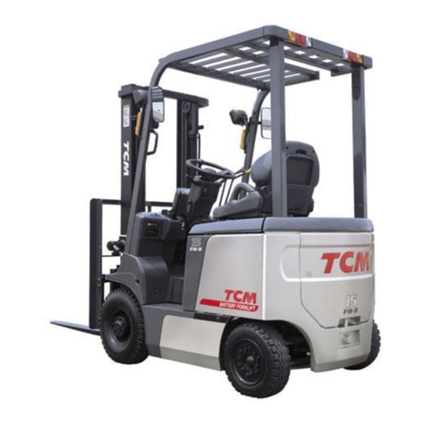
TCM FB-8 Series User manual

No. SEB‑7POBE
TCM
⑮
@~æ.
WD@
国間
A
間切
I&
[S
FORKLIFTTRUCK
Counter 8alanced
FB唱O‑S
FB唱5‑s
FB
唱8‑s
FB20‑s
FB25‑s
FB30‑s
FB25‑SLB
FB25‑sv
FB30‑sv
FB35‑ss
TCMCORPORATION


FOREWORD
The new TCM’s FB-8 Series battery-powered forklift trucks are provided with a newly designed
speed control system and AC motors for both the traveling and load handling systems to assure
high performance operation.
The trucks of this series are also provided with a self-diagnosis function which keeps watching
the operating statuses of the main control systems of the truck. If the truck has a trouble, the
function detects the trouble and displays the result of diagnosis. The maintainability is thus
improved.
As for mobility, since the high capacity batteries and high power drive motor are used, the rst-
class acceleration, gradeability, and traveling performance are achieved.
Controllability is also improved by the standard equipped power steering unit.
To save power, the acceleration and traveling speeds are selectable and made changeable
according to working conditions. Also for effective use of the battery, a regenerative device is
provided to send back counter electromotive force to the battery.
This Service Manual is intended to provide the maintenance personnel with helpful information
of the structures of the major components and with instructions on the maintenance and repair of
such components. We hope it will be much help for your servicing and maintenance operations.
December 2012


SPECIFICATIONS (1)
Truck model
Item FB10-8 FB15-8 FB18-8 FB20-8
Performance
Max. load kg [lbs] 1000 [2000] 1500 [3000] 1750 [3500] 2000 [4000]
Load center mm [in.] 500 [24] ←←←
Max. lifting height mm [in.] 3000 [118.1] ←←←
Tilting angle
Fwd °6←←←
Bwd °12 ←←←
Free lift Amm [in.] 155 [6.1] ← ← 110 [4.3]
Mast tilting time (Fwd - Bwd) s 2.0 - 1.4 ← ← 2.7 - 2.0
Fork lifting speed
Loaded mm/s [fpm] 390 [76.8] 350 [68.9] 330 [65.0] 290 [57.1]
Unloaded mm/s [fpm] 580 [114.2] ← ← 510 [100.4]
Travel speed
Loaded km/h [mph] 14 [8.7] ←←←
Unloaded km/h [mph] 16 [9.9] ←←←
Gradeability
(Starting on an uphill when loaded) 1/7 ←←←
Min. turning radius
(Outermost part of truck)
EPS: Bmm [in.] 1700 [66.9] ←1790 [70.5] 1950 [76.8]
Orbitrol type: 1800 [70.9] ←1890 [74.4] 2070 [81.5]
Min. intersecting aisle Cmm [in.] 1690 [66.5] ←1730 [68.1] 1895 [79.6]
Dimensions mm [in.]
Overall length (includ. fork) D2875 [113.2] ←2975 [117.1] 3315 [130.5]
Overall width E1070 [42.1] ← ← 1150 [45.3]
Overall height (Overhead guard)
F2080 [81.9] ← ← 2125 [83.7]
EXN:
2140 [84.3] ← ← 2185 [86.0]
Overall extended height 4030 [158.7] ←←←
Wheel base G1250 [49.2] ←1350 [53.2] 1400 [55.1]
Tread
Front wheels H910 [35.8] ← ← 955 [37.6]
Rear wheels J900 [35.4] ← ← 950 [37.4]
Fork overhang K375 [14.8] ← ← 435 [17.1]
Rear overhang L330 [13.0] ← ← 410 [16.1]
Fork size
(Length Lx Width Mx Thickness N)
920x100x35
[36.2x3.9x1.4] ← ← 1070x122x40
[42.1x4.8x1.6]
Fork spacing Q200 - 920
[7.9 - 36.2] ← ← 245 -1020
[9.6 - 40.2]
Minimum under clearance 90 [3.5]
(Rear axle) ← ← 100 [3.9]
(Rear axle)
Tow pin height 390 [15.4] ← ← 440 [17.3]
Weight
Service Weight with std. batteries kg [lbf] 2680 [5908] 2710 [5976] 3030 [6680] 3500 [7716]
The values in the Performance section are given for trucks operating in the Super mode.

SPECIFICATIONS (2)
Truck model
Item FB25-8 FB25-8LB
FB25-8V FB30-8
FB30-8V FB35-8S
Performance
Max. load kg [lbs] 2500 [5000] ←3000 [6600] 3500 [7000]
Load center mm [in.] 500 [24] ←←←
Max. lifting height mm [in.] 3000 [118.1] ←←←
Tilting angle
Fwd °6←←←
Bwd °12 ←←10
Free lift Amm [in.] 110 [4.3] ←165 [6.5] 170 [6.7]
Mast tilting time (Fwd - Bwd) s 2.7 - 2.0 ←2.5 - 2.0 3.5 - 2.5
Fork lifting speed
Loaded mm/s [fpm] 265 [52.2] ←290 [57.1] 240 [47.2]
Unloaded mm/s [fpm] 510 [100.4] ←490 [96.5] 410 [80.7]
Travel speed
Loaded km/h [mph] 14 [8.7] 13.5 [8.4] 14 [8.7] ←
Unloaded km/h [mph] 16 [9.9] 15.5 [9.6] 15 [9.3] ←
Gradeability
(Starting on an uphill when loaded) 1/7 1/8 ←1/10
Min. turning radius
(Outermost part of truck)
EPS: Bmm [in.] 1970 [77.6] 2065 [81.3] 2140 [84.3] 2360 [92.9]
Orbitrol type: 2100 [82.7] 2200 [86.6] 2290 [90.2] 2500[98.4]
Min. intersecting aisle Cmm [in.] 1905 [75.0] 1955 [76.9] 2050 [80.7] 2250 [88.6]
Dimensions mm [in.]
Overall length (includ. fork) D3355 [132] 3460 [136] 3580 [140.9] 3805 [149.8]
Overall width E1150 [45.3] ←1225 [48.2] 1380 [54.3]
Overall height (Overhead guard)
F2125 [83.7]
LB: 2250 [88.6]
V: 2100 [82.7]
2190 [86.2]
V: 2100 [82.7] 2190 [86.2]
Overall extended height 4030 [158.7] ←4260 [167.7 ] ←
Wheel base G1400 [55.1] 1545 [60.8] 1600 [63.0] 1800 [70.9]
Tread
Front wheels H955 [37.6] ←1000 [39.4] 1140 [44.9]
Rear wheels J950 [37.4] ←←←
Fork overhang K435 [17.1] ←480 [18.9] 500 [19.7]
Rear overhang L450 [17.7] 410 [16.1] 430 [16.9] ←
Fork size
(Length Lx Width Mx Thickness N)
1070x122x40
[42.1x4.8x1.6] ←1070x125x45
[42.1x4.9x1.8] 1070x150x50
[42.1x5.9x2.0]
Fork spacing Q245 - 1020
[9.6 - 40.2] ←250 - 1090
[9.8 - 42.9] 300 - 1090
[11.8 - 42.9]
Minimum under clearance 100 [3.9]
(Rear axle) 90 [3.5]
(Rear axle) ← ←
Tow pin height 440 [17.3] ←475 [18.7] ←
Weight
Service Weight with std. batteries kg [lbf] 3910 [8620]
LB: 4400 [9700]
V: 4290 [9460]
4640 [10200] 5240 [11600]
The values in the Performance section are given for trucks operating in the Super mode.

Unit: mm [in.]
Fig. 1 Overall Dimensions
E
N
J
Q
H
B
C
A
1~2.5t : 4030 3~3.5t : 4260
3000
P
F
M K DG L
1 - 2.5 t: 4030 [158.7] 3 - 3.5 t: 4260 [167.7]
3000 [ 118.1]

Table 1. Maintenance Standard List
Truck model
Item FB10-8
FB15-8 FB18-8 FB20-8
FB25-8
FB25-8LB
FB25-8V
FB30-8
FB30-8V FB35-8S
Electric system
Motor brush size and wear
limit
Traction mm [in.] * * * * *
Pump mm [in.] * * * * *
Power steering
(EPS type only)
mm [in.]
22 - 13 [0.87 - 0.51]
←←←←
Motor brush spring force
Traction
N{kgf}[lbf]
*****
Pump
N{kgf}[lbf]
*****
Power steering
(EPS type only)
N{kgf}[lbf]
11.8 {1.2} [2.7] ←←←←
Voltage relay check voltage (20°C) (V) 58.8±0.2 ← ← 87.0±0.2 ←
Timer operating time Normal (h) 14 ←←←←
Fail (h) 16 ←←←←
Controller current limit value
(Traction motor lock current) P (A) * * * * *
E (A) * * * * *
Fuses
Traveling system main circuit
(A) 400 ←500 400 ←
For control circuit
(battery power supply) (A) 10 ←←←←
Lift lock (A) 2 ←←←←
Battery charger primary side
(thermal relay) (A) 24 ←34 40 ←
Battery charger secondary side
(A) 130 ←130/200 130 ←
For control circuit
(key switch power supply) (A) 10 ←←←←
For accessory circuit (A) 10 ←←←←
Steering axles and wheels
Tire air
pressure
Front (single)
(double)
MPa{kgf/cm2}[psi]
0.85±0.03 {8.5±0.3}
[123.3±4.35]
0.7±0.03 {7.0±0.3}
[101.5±4.4]
1.00±0.03 {10.0±0.3}
[145.0±4.35]
←
←
←
0.8±0.03 {8.0±0.3}
[116.0±4.35]
←
0.85±0.03 {8.5±0.3}
[123.3±4.35]
←
Rear
MPa{kgf/cm2}[psi]
0.85±0.03 {8.5±0.3}
[123.3±4.35]
←
0.90±0.03 {9.0±0.3}
[130.5±4.35]
←*
Hub nut tightening torque Front
N-m{kgf-m}[lbf-ft]
150-175 {15-17.5}
[110.6-129.1]
←
370-420 {37.8-42.8}
[273-310]
470.7-549.2
{48-56} [347-405] ←
Rear
N-m{kgf-m}[lbf-ft]
127.5-190.3 13.0-19.4}
[94-140]
←←←←
Axle shaft mounting bolt tightening torque
N-m{kgf-m}[lbf-ft]
96.1-110.8 {9.8-11.3}
[70.9-81.7]
←*
96.1-110.8 {9.8-11.3}
[70.9-81.7]
←
Split rim assembly bolt
tightening torque
Front
N-m{kgf-m}[lbf-ft]
60.8-90.2 {6.2-9.2}
[44.8-66.5]
←***
Rear
N-m{kgf-m}[lbf-ft]
30.4-45.1 {3.1-4.6}
[22.4-33.3]
←
60.8-90.2 {6.2-9.2}
[44.8-66.5]
← ←
Steering axle gap in fore-and-aft direction
mm [in.] less than 1 [0.039] ←←←←
Steering axle center pin diameter (EPS type only)
mm [in.] 40+0
-0.1 [1.57+0
-0.004 ]←50+0
-0.1 [1.97 +0
-0.004 ]← ←
Steering axle bushing inner diameter mm [in.] 40+0.1
-0 [1.57+0
-0.004 ]←50+0
-0.1 [1.97 +0
-0.004 ]← ←
Steering system
Steering wheel play in rotating direction
mm [in.] 75±25 [2.95±0.98] ←←←←
Camber angle °1←←←←
Minimum turning radius
mm [in.]
EPS type 1700+50
-0 [66.9+1.97
-0 ] 1790+50
-0 [70.5+1.97
-0 ]
FB20: 1950
+50
-0
[76.8
+1.97
-0
]
2140+50
-0 [84.3+1.97
-0 ] 2360+50
-0 [92.9+1.97
-0 ]
EPS type
FB25: 1970
+50
-0
[77.6
+1.97
-0
]
Orbitrol type 1800 [70.9] 1890 [74.4] FB20: 2070 [81.5]
FB25: 2100 [82.7] 2290 [90.2] 2500 [98.4]
Power steering relief pressure setting
MPa{kgf/cm2}[psi]
*****
Brake system
Brake pedal height mm [in.] 97 [3.8] ← ← 110 ←
Brake pedal play mm [in.]
10±5 [0.393±0.197]
←←←←
Brake pedal height when depressed fully
mm [in.]
60±10 [2.362±0.393]
←←←←
Foot pedal braking effect Unloaded within 2.5 m ←←←←
Loaded within 2.5 m ←←←←
Parking brake lever operating force
N{kgf}[lbf]
*****
Parking brake braking effect Unloaded
Held in position on
20% slope
←
Held in position on
16.7% slope
← ←
Loaded
Held in position on
14.3% slope
← ←
Held in position on
12.5% slope
←
Clearance between brake drum and lining
mm [in.] 0.25-0.4
[0.0098-0.016] ←←←←
Lining thickness mm [in.] 5+0
-3 [0.197+0
-0.118 ]←5.6+0
-3.6 [0.22+0
-0.142 ] 8+0
-6 [0.31+0
-0.236 ]] ←
Brake drum inner diameter mm [in.] 254+2
-0 [10+0.079
-0 ]←280+2
-0 [11.0+0.079
-0 ] 314+2
-0 [12.4+0.079
-0 ]←
Brake drum mounting bolt tightening torque
N-m{kgf-m}[lbf-ft]
* *
215.7-235.4 {22-24}
[159.1-173.6]
470.7-549.2 {48-56}
[347.2-405.1]
←
Back plate mounting bolt tightening torque
N-m{kgf-m}[lbf-ft]
117.7-137.3
{12-14} [86.8-101.3]
←
205.9-225.6 {
21-23} [151.9-166.4]
← ←
Load han-
dling system
Fork thickness mm [in.] 35+0
-4 [1.38+0
-0.157 ]←40+0
-4 [1.57+0
-0.157 ] 45+0
-6 [1.77+0
-0.236 ] 50+0
-5 [1.97+0
-0.197 ]
Opening of fork tips mm [in.] within 10 [0.394] ←←←←
Difference in height between right and left fork tips
mm [in.] 0±5 [0±0.197] ←←←←
Chain length mm [in.] 19.05+50
-0 ← ← 25.4+50
-0 ←
Hydraulic system
Tilt cylinder piston rod lock bolt and nut
tightening torque
N-m{kgf-m}[lbf-ft]
107.9±20.6 {11.0±2.1}
[79.6±15.2]
←←←←
Lift cylinder natural drop mm [in.]/min
less than 75 [2.95]/10
←
less than 60 [2.36]/10 less than 50 [1.97]/10
←
Tilt cylinder natural tilt (extension of piston rod)
mm [in.]/min
less than 25 [0.98]/10
←
less than 20 [0.79]/10
← ←
Fork lifting speed (Unloaded) mm [in.]/sec 580+50
-0 [22.8+1.97
-0 ]←510+50
-0 [20.1+1.97
-0 ] 490+50
-0 [19.3+1.97
-0 ] 410+50
-0 [16.1+1.97
-0 ]
Control valve relief pressure setting
MPa{kgf/cm2}[psi]
13.7+0.49
-0 {140+5
-0 }
[1990+71.1
-0 ]15.7+0.49
-0 {160+5
-0 }
[2277+71.1
-0 ]17.2+0.49
-0 {175+5
-0 }
[2495+71.1
-0 ]← ←
Safety
device
Overhead guard mounting bolt and nut
tightening torque
N-m{kgf-m}[lbf-ft]
31.4-47.1 {3.2-4.8}
[23.2-34.7]
←←←←
Load backrest mounting bolt tightening torque
N-m{kgf-m}[lbf-ft]
59.3±11.9 {6.05±1.21}
[43.7±8.8]
←←←←

01. CAUTION TO TAKE WHEN SERVICING THE TRUCK
* Before servicing the truck, make sure to:
1. Park the truck on a level surface and jack up the drive wheel off the oor or ground.
Make sure there is no obstacle above and around the truck before operating the load handling
system.
* Caution to take when measuring, inspecting or repairing:
2. Before connecting or disconnecting wire harness couplers, make sure the key switch is turned off
and the battery receptacles are disconnected.
3. When measuring the resistance of wire harness couplers with a multimeter, connect the probes to
the lead wire side of the coupler.
4. When inspecting the truck with the forks raised, support the forks to prevent them from falling
unexpectedly.
5. When inspecting the truck with the mast advanced, put a pallet between the mast and the front
guard of the truck to prevent the mast from retracting unexpectedly.
6. Inspection and repair of the truck must be performed only by qualified service personnel
authorized by TCM.
Reach model
Counterbalanced model

02. BASIC SERVICING KNOWLEDGE
1. Installing bearings
When installing a bearing onto a shaft, tap its
inner race with a mallet as shown in Figure 02.1.
When installing a bearing into a case, tap its outer
race.
When removing, use the same procedure as for
installing.
2. “O”-rings
①Use “O”-rings free from molding fault or damage.
②Clean “O”-rings and their mounting area and apply grease or hydraulic oil to them.
③When installing “O”-rings, do not expand them so excessively that they suffer permanent
deformation. Also do not roll them when installing; otherwise they might stay twisted, causing oil
leakage.
④When using an “O”-ring and back-up ring as
a set, such as when hydraulic pressure is high,
position the “O”-ring at the side which receives
the oil pressure.
3. Oil seals
①Oil seals should be installed with the seal lip pointed toward the lubrication or hydraulic oil.
②When installing an oil seal on a housing, apply a thin coat of packing cementing agent on the
oil seal outer ring and inside the housing to prevent oil leakage through the fitting area. It is
recommended to use a suitable jig to apply uniform pressure when mounting oil seals.
Fig. 02.1 Installing bearings
JIG
Fig. 02.2 “O”-ring location
Pressure
Fig. 02.3 Installing Oil Seal
JIG JIG JIG

③When installing an oil seal onto a shaft, apply
lubricating oil or grease to its seal lip and the
mounting surface of the shaft. For a double-
lip type, fill grease by 1/3 to 1/2 of the space
between the lips.
When inserting an oil seal into a case, use care
to damage the seal lip. It is good practice to use
a suitable conical sleeve.
4. Using LOCTITE
(1) Procedure for using LOCTITE
①Clean or degrease the surface of parts you are going to apply LOCTITE, using trichloroethylene,
acetone, ether or alkaline solution.
② Blow dry them with compressed air or allow to air dry at room temperature sufciently.
③ Apply specied LOCTITE.
(2) Removing parts
When removing parts which were installed with the application of LOCTITE, use tools such as a
spanner, wrench, and pulley remover.
If you fear that a part may break due to the effect of LOCTITE if forcibly removed, heat the part to
200 to 250°C [392 to 482°F] with a soldering iron or gas burner.
Remember that parts are very hot after heating. Use caution not to get burnt when
removing them.
(3) Reinstalling parts
①When destroyed, LOCTITE remains as white powder on the threads of bolts.
You can apply a
new coat of LOCTITE again over their surface.
Note: For example, if a bolt turns slightly due to bolt torque checking, remove the bolt and apply
LOCTITE again and reinstall.
② If LOCTITE is used for the surface of a ange, it is necessary to remove hardened LOCTITE with
a wire brush when reinstalling the ange.
5. How to use a power wrench
Power wrenches have their respective torque multiplying factors. Refer to the product catalog of
each power wrench.
It should be noted that a value obtained by multiplying the output torque of a torque wrench by the
multiplying factor of a power wrench is not necessarily an output torque.
Remember this especially when the tightening torque is strictly specied.
Fig. 02.4 Installing Oil Seal
SLEEVE
JIG

03. CLEANING
1. General metallic parts
① Clean parts thoroughly using cleaning uid. It is recommended that parts be immersed in cleaning
uid and moved up and down slowly until all old lubricant and foreign material is dissolved and
parts are thoroughly cleaned.
②Cast parts should be cleaned with cleaning solvent or steam cleaned.
③If a part is severely contaminated, use a wire brush or a piece of wood or metal to scrape off
contaminants from the part. Wash it in cleaning fluid once, before cleaning it completely.
However, do not use a wire brush for cleaning sliding surfaces or machined surfaces.
④Oil passages must be cleaned with a steam cleaner. After checking for clogging with a piece of
wire, they also should be cleaned with cleaning uid or with compressed air.
⑤Some parts may be cleaned in hot solution tanks with mild alkaline solution. Parts should remain
in solution long enough to be thoroughly cleaned and warmed.
This will aid the evaporation of the cleaning solution and rise water. Parts cleaned in solution
tanks must be thoroughly rinsed with clean water to remove all traces of alkali.
Careshouldbeexercisedtoavoidskinrashes,rehazardsandinhalationofvaporswhen
using solvent type cleaners.
⑥If alloy parts, such as bearing shells or bushings, are cleaned with alkaline solution, they are apt to
corrode due to ionization. Such parts should be cleaned with kerosene, Tricrene solvent vapor or
“Magnus” uid.
⑦After cleaning, parts must be thoroughly dried with compressed air.
2. Bearings
①To dislodge solidified particles of lubricant, immerse bearings in cleaning fluid and remove
them from the uid. On a clean work bench, tap the bearing softly with a soft mallet to dislodge
solidied particles.
②When drying bearings, be careful to direct air stream across bearing to avoid spinning.
3. Rubber parts
①When rubber parts need to be cleaned, use alcohol or wipe them clean with a soft cloth.
②Never use gasoline, diesel fuel or kerosene for cleaning. Use the same kind of oil for which the
rubber part will be used.

04. STANDARD BOLT TIGHTENING TORQUE
See the section “04. STANDARD BOLT TIGHTENING TORQUE” for the torques of standard
bolts when they are used for general applications. Refer to the Shop Manual and Service Manual of
your truck model when:
1) Special nuts are used.
2) Synthetic resin or rubber is used for tightening.
3) Specied tightening torque is given.
Table 04.1 Strength
Strength Indication on bolt Material
4.6
SS400
(The number may be omitted.)
6.8
S45C
8.8
SCM435
Boron steel
(“B” may be omitted.)
10.9
SCM435
Boron steel
(“B” may be omitted.)

Table 04.2
Name Shape Thread size Material Division by
strength Surface
treatment Part number
Hex. head
bolt
Normal M4 - M8 coarse and
M10 - M39 ne
SS400 4.6
Black 01101- Nominal symbol
SS400 4.6
Yellow
chromate
01100- “
S45C 6.8 01103- “
SCM435, Boron steel
8.8 01106- “
SCM435, Boron steel
10.9 01107- “
BsBME1 — 01108- “
Coarse M10 - M39 coarse
SS400 4.6
Black
01112- “
SS400 4.6
Yellow
Chromate
01110- “
S45C 6.8 01113- “
SCM435, Boron steel
8.8 01116- “
SCM435, Boron steel
10.9 01119- “
Full thread
(normal,
coarse) M10 - M39 coarse
SS400 4.6
Black
01115- “
SS400 4.6
Yellow
Chromate
01111- “
S45C 6.8 01114- “
SCM435, Boron steel
8.8 01117- “
Full thread
(normal) M4 - M8 coarse and
M10 - M39 ne
SS400 4.6
Black
01121- “
SS400 4.6
Yellow
Chromate
01120- “
S45C 6.8 01123- “
SCM435, Boron steel
8.8 01126- “
SCM435, Boron steel
10.9 01127- “
BsBME1
— 01128- “
w. socket
head M4 - M8 coarse and
M10 - M39 ne
SS400 4.6
Black
01131- “
SS400 4.6
Yellow
Chromate
01130- “
S45C 6.8 01133- “
SCM435, Boron steel
8.8 01136- “
SCM435, Boron steel
10.9 01137- “
w. hole in
threads M4 - M8 coarse and
M10 - M39 ne
SS400 4.6
Black
01161- “
SS400 4.6
Yellow
Chromate
01160- “
S45C 6.8 01163- “
SCM435, Boron steel
8.8 01166- “
SCM435, Boron steel
10.9 01167- “
• Designation of screws: Each part number consists of a screw type designation and a nominal symbol.
Example: 01130-16050 (hex. bolt 4.6, M16 x 50, w. socket head)

M 4
M 5
M 6
M 8
M 10
M 12
M 14
M 16
M 18
M 20
M 22
M 24
M 27
M 30
M 33
M 36
M 39
M 4
M 5
M 6
M 8
M 10
M 12
M 14
M 16
M 18
M 20
M 22
M 24
M 27
M 30
M 33
M 36
M 39
0.50
0.50
0.75
1.00
1.25
1.25
1.50
1.50
1.50
1.50
1.50
2.00
2.00
2.00
2.00
3.00
3.00
0.70
0.80
1.00
1.25
1.50
1.75
2.00
2.00
2.50
2.50
2.50
3.00
3.00
3.50
3.50
4.00
4.00
1.36
2.87
4.59
10.9
21.2
39.1
61.7
95.9
141
198
270
334
489
686
931
1130
1460
1.15
2.36
3.98
9.81
19.5
34.2
55.0
86.9
118
171
234
293
436
588
810
1030
1350
13.9
29.3
46.8
111
216
399
629
978
1440
2020
2750
3410
4990
7000
9490
11500
14900
11.7
24.1
40.6
100
199
349
561
886
1200
1740
2390
2990
4450
6000
8260
10500
13800
1.09 - 1.63
2.30 - 3.44
3.67 - 5.55
8.69 - 13.3
17.1 - 25.4
31.4 - 47.1
49.3 - 74.0
76.8 - 115
113 - 170
159 - 238
216 - 324
268 - 401
391 - 587
550 - 824
744 - 1120
903 - 1350
1170 - 1740
0.92 - 1.38
1.89 - 2.82
3.20 - 4.79
7.84 - 11.7
15.6 - 23.4
27.5 - 41.1
43.9 - 65.9
69.5 - 104
94.6 - 142
136 - 204
187 - 252
234 - 352
349 - 524
471 - 706
648 - 972
828 - 1250
1080 - 1140
11.1 - 16.6
23.5 - 35.1
37.4 - 56.1
88.6 - 133
174 - 259
320 - 480
503 - 755
783 - 1170
1150 - 1730
1620 - 2430
2200 - 3300
2730 - 4090
3990 - 5990
5610 - 8400
7590 - 11400
9210 - 13800
11900 - 17700
9.4 - 14.1
19.3 - 28.8
32.6 - 48.8
79.9 - 119
159 - 239
280 - 419
448 - 672
709 - 1060
965 - 1450
1390 - 2080
1910 - 2570
2390 - 3590
3560 - 5340
4800 - 7200
6610 - 9910
8440 - 12700
11000 - 11650
1.21
2.53
4.06
9.62
18.8
34.5
54.2
84.3
125
175
235
293
429
600
812
991
1280
1.03
2.11
3.56
8.74
17.5
30.4
48.8
77.0
105
150
207
259
385
521
714
914
1190
12.3
25.8
41.4
98.1
192
352
553
860
1270
1780
2400
2990
4370
6120
8280
10100
13100
10.5
21.5
36.3
89.1
178
310
498
785
1070
1530
2110
2640
3930
5310
7280
9320
12100
0.96 - 1.44
2.02 - 3.00
3.25 - 4.87
7.70 - 1.15
15.0 - 22.6
27.7 - 41.5
43.4 - 65.3
67.5 - 100
99.1 - 148
139 - 208
188 - 282
234 - 351
342 - 515
480 - 720
650 - 974
792 - 1190
1020 - 1540
0.82 - 1.24
1.70 - 2.53
2.85 - 4.29
7.00 - 10.5
13.9 - 20.9
24.4 - 36.6
39.0 - 55.8
61.6 - 92.4
84.1 - 127
121 - 180
165 - 248
208 - 312
308 - 463
417 - 624
572 - 857
731 - 1100
953 - 1430
9.8 - 14.7
20.6 - 30.9
33.1 - 49.7
78.5 - 117
153 - 230
282 - 423
443 - 666
1688 - 1030
1010 - 1510
1420 - 2120
1920 - 2880
2390 - 3580
3490 - 5250
4890 - 7340
6630 - 9930
8080 - 12100
10400 - 15700
8.4 - 12.6
17.3 - 25.8
29.1 - 43.7
71.4 - 107
142 - 213
249 - 373
398 - 597
628 - 942
858 - 1290
1230 - 1840
1680 - 2530
2120 - 3180
3140 - 4720
4250 - 6360
5830 - 8740
7450 - 11200
9720 - 14600
0.99
2.08
3.34
7.93
15.5
28.4
44.7
69.5
102
143
194
241
352
493
669
815
1050
0.8
1.7
2.9
7.2
14.3
25.1
40.2
63.5
86.6
125
171
214
318
429
588
753
981
10.1
21.2
34.1
80.9
158
290
456
709
1040
1460
1980
2460
3590
5030
6820
8310
10700
8.66
17.8
30.0
73.5
146
256
410
647
883
1270
1740
2180
3240
4370
6000
7680
10000
0.79 - 1.19
1.66 - 2.50
2.68 - 4.01
6.34 - 9.51
12.5 - 18.6
22.7 - 34.1
35.9 - 53.7
55.5 - 83.4
81.5 - 123
114 - 172
155 - 233
193 - 289
282 - 424
395 - 592
534 - 802
652 - 979
844 - 1270
0.68 - 1.02
1.39 - 2.08
2.35 - 3.53
5.77 - 8.65
11.5 - 17.3
20.1 - 30.1
32.3 - 48.3
50.8 - 76.1
69.3 - 104
99.1 - 149
136 - 204
172 - 257
254 - 381
342 - 515
471 - 706
602 - 903
785 - 1180
8.1 - 12.1
16.9 - 25.5
27.3 - 40.9
64.6 - 97.0
127 - 190
231 - 348
366 - 548
566 - 850
831 - 1250
1160 - 1750
1580 - 2380
1970 - 2950
2880 - 4320
4030 - 6040
5450 - 8180
6650 - 9980
8610 - 12900
6.9 - 10.4
14.2 - 21.2
24.0 - 36.0
58.8 - 88.2
117 - 176
205 - 307
329 - 493
518 - 776
707 - 1060
1010 - 1520
1390 - 2080
1750 - 2620
2590 - 3890
3490 - 5250
4800 - 7200
6140 - 9210
8000 - 12000
0
㨙kgHE㨙 0㨙 kgHE㨙 0㨙 kgHE㨙 0㨙 kgHE㨙 0㨙 kgHE㨙 0㨙 kgHE㨙
Lubrication
condition
Class Nominal
size Pitch Target value Allowable value
Dry
Table 04.3 Tightening torque chart (Division by strength: 4.6)
LOCTITE262 Lubricant
Target value Allowable value Target value Allowable value
Metric, fine systemMetric, coarse system

M 4
M 5
M 6
M 8
M 10
M 12
M 14
M 16
M 18
M 20
M 22
M 24
M 27
M 30
M 33
M 36
M 39
M 4
M 5
M 6
M 8
M 10
M 12
M 14
M 16
M 18
M 20
M 22
M 24
M 27
M 30
M 33
M 36
M 39
0.50
0.50
0.75
1.00
1.25
1.25
1.50
1.50
1.50
1.50
1.50
2.00
2.00
2.00
2.00
3.00
3.00
0.70
0.80
1.00
1.25
1.50
1.75
2.00
2.00
2.50
2.50
2.50
3.00
3.00
3.50
3.50
4.00
4.00
2.71
5.74
9.14
21.7
42.4
78.3
123
192
282
396
537
668
978
1370
1860
2250
2920
2.29
4.72
7.95
19.6
38.6
68.4
110
174
235
338
468
585
872
1180
1620
2070
2700
27.6
58.5
93.2
221
432
798
1250
1960
2870
4040
5480
6810
9970
14000
19000
22900
29800
23.3
48.1
81.1
200
397
697
1120
1770
2400
3450
4770
5970
8890
12000
16500
21100
27500
2.17 - 3.26
4.59 - 6.87
7.32 - 11.0
17.4 - 26.0
33.8 - 50.9
62.6 - 93.9
98.1 - 148
153 - 229
225 - 337
317 - 476
431 - 645
534 - 800
782 - 1170
1100 - 1650
1490 - 2330
1790 - 2700
2330 - 3510
1.82 - 2.75
3.77 - 5.66
6.36 - 9.55
15.7 - 23.4
31.2 - 46.8
54.6 - 82.1
87.8 - 132
139 - 208
189 - 282
271 - 407
374 - 562
469 - 702
697 - 1050
940 - 1410
1280 - 1940
1650 - 2480
2160 - 3240
22.1 - 33.2
46.8 - 70.1
74.6 - 112
177 - 265
345 - 519
638 - 957
1000 - 1510
1560 - 2340
2290 - 3440
3230 - 4850
4390 - 6580
5440 - 8160
7970 - 11900
11200 - 16800
15200 - 22700
18300 - 27500
23800 - 35800
18.6 - 28.0
38.4 - 57.7
64.9 - 97.4
160 - 239
318 - 477
557 - 837
895 - 1350
1420 - 2120
1930 - 2880
2760 - 4150
3810 - 5730
4780 - 7160
7110 - 10700
9580 - 14400
13100 - 19800
16800 - 25300
22000 - 33000
2.40
5.05
8.10
19.2
37.5
68.9
109
169
247
347
471
585
855
1200
1620
1980
2560
2.06
4.21
7.13
17.5
34.8
60.9
97.6
154
210
300
413
519
770
1040
1430
1820
2380
24.5
51.5
82.6
196
382
703
1110
1720
2520
3540
4800
5970
8720
12200
16500
20200
26100
21.0
42.9
72.7
178
355
621
995
1570
2140
3060
4210
5290
7850
10600
14600
18600
24300
1.92 - 2.87
4.04 - 6.06
6.48 - 9.72
15.4 - 23.0
30.0 - 45.0
55.1 - 82.7
86.9 - 129
135 - 202
198 - 296
278 - 416
376 - 565
469 - 702
685 - 1030
958 - 1440
1290 - 1950
1580 - 2370
2050 - 3070
1.65 - 2.47
3.36 - 5.06
5.70 - 8.54
14.0 - 21.0
27.8 - 41.7
48.6 - 73.1
78.1 - 117
123 - 185
168 - 252
240 - 360
330 - 495
414 - 623
616 - 924
831 - 125
1140 - 1710
1460 - 2190
1900 - 2840
19.6 - 29.3
41.2 - 61.8
66.1 - 99.1
157 - 235
306 - 459
562 - 843
886 - 1320
1380 - 2060
2020 - 3020
2830 - 4240
3830 - 5760
4780 - 7160
6980 - 10500
9770 - 14700
13200 - 19900
16100 - 24200
20900 - 31300
16.8 - 25.2
34.3 - 51.6
58.1 - 87.1
143 - 214
283 - 425
496 - 745
796 - 1190
1250 - 1890
1710 - 2570
2450 - 3670
3370 - 5050
4220 - 6350
6280 - 9420
8470 - 12700
11600 - 17400
14900 - 22300
19400 - 29000
1.98
4.15
6.68
15.8
30.9
56.8
89.4
139
203
285
386
481
704
991
1340
1630
2110
1.70
3.47
5.87
14.4
28.6
50.2
80.3
127
173
247
340
428
634
855
1180
1500
1960
20.2
42.3
68.1
161
315
579
912
1420
2070
2910
3940
4910
7180
10100
13700
16600
21500
17.3
35.4
59.9
147
292
512
819
1290
1760
2520
3470
4360
6460
8720
12000
15300
20000
1.58 - 2.38
3.33 - 4.98
5.34 - 8.01
12.7 - 19.0
24.7 - 37.1
45.5 - 68.2
71.6 - 107
111 - 168
163 - 244
229 - 343
310 - 465
385 - 579
564 - 845
788 - 1180
1070 - 1600
1290 - 1950
1690 - 2530
1.36 - 2.03
2.78 - 4.17
4.70 - 7.04
11.5 - 17.3
22.9 - 34.4
40.1 - 60.1
64.2 - 96.4
101 - 152
138 - 208
198 - 297
272 - 409
341 - 513
507 - 760
685 - 1030
940 - 1410
1200 - 1790
1570 - 2340
16.1 - 24.3
33.9 - 50.8
54.4 - 81.7
129 - 194
252 - 378
464 - 695
730 - 1090
1130 - 1700
1660 - 2490
2330 - 3500
3160 - 4740
3930 - 5900
5750 - 8620
8040 - 12000
10900 - 16300
13200 - 19900
17200 - 25800
13.9 - 20.7
28.3 - 42.5
47.9 - 71.8
117 - 176
233 - 351
409 - 613
655 - 983
1030 - 1550
1410 - 2120
2020 - 3030
2770 - 4170
3480 - 5230
5170 - 7750
6980 - 10500
9580 - 14400
12200 - 18300
16000 - 23900
0
㨙kgHE㨙 0㨙 kgHE㨙 0㨙 kgHE㨙 0㨙 kgHE㨙 0㨙 kgHE㨙 0㨙 kgHE㨙
Lubrication
condition
Class Nominal
size Pitch Target value Allowable value
Dry
Table 04.4 Tightening torque chart (Division by strength: 6.8)
LOCTITE262 Lubricant
Target value Allowable value Target value Allowable value
Metric, fine systemMetric, coarse system

M 4
M 5
M 6
M 8
M 10
M 12
M 14
M 16
M 18
M 20
M 22
M 24
M 27
M 30
M 33
M 36
M 39
M 4
M 5
M 6
M 8
M 10
M 12
M 14
M 16
M 18
M 20
M 22
M 24
M 27
M 30
M 33
M 36
M 39
0.50
0.50
0.75
1.00
1.25
1.25
1.50
1.50
1.50
1.50
1.50
2.00
2.00
2.00
2.00
3.00
3.00
0.70
0.80
1.00
1.25
1.50
1.75
2.00
2.00
2.50
2.50
2.50
3.00
3.00
3.50
3.50
4.00
4.00
3.62
7.65
12.2
28.9
56.5
104
164
256
377
529
718
890
1300
1830
2480
3010
3900
3.06
6.30
10.6
26.1
52.1
91.2
146
232
315
452
624
782
1160
1570
2160
2770
3600
36.9
78.0
124
295
576
1060
1670
2610
3840
5390
7320
9080
13300
18700
25300
30700
39800
31.2
64.2
108
266
531
930
1490
2370
3210
4610
6360
7970
11800
16000
22000
28200
36700
2.89 - 4.34
6.12 - 9.18
9.78 - 14.7
23.1 - 34.7
45.2 - 67.9
83.6 - 126
131 - 197
204 - 307
301 - 451
423 - 635
574 - 861
712 - 1070
1040 - 1570
1460 - 2190
1980 - 2970
2400 - 3610
3120 - 4680
2.45 - 3.67
5.03 - 7.55
8.50 - 12.7
20.9 - 31.0
41.6 - 62.5
73.1 - 109
117 - 177
185 - 279
252 - 379
362 - 543
499 - 749
626 - 938
931 - 1400
1260 - 1880
1730 - 2590
2210 - 3310
2880 - 4320
29.5 - 44.3
62.4 - 93.6
99.7 - 150
236 - 354
461 - 692
852 - 1280
1340 - 2010
2080 - 3130
3070 - 4600
4310 - 6470
5850 - 8780
7260 - 10900
10600 - 16000
14900 - 22300
20200 - 30300
24500 - 36800
31800 - 47700
25.0 - 37.4
51.3 - 77.0
86.7 - 130
213 - 319
424 - 638
745 - 1110
1190 - 1800
1890 - 2840
2570 - 3860
3690 - 5540
5090 - 7640
6380 - 9560
9490 - 14300
12800 - 19200
17600 - 26400
22500 - 33800
29400 - 44100
3.20
6.73
10.8
25.6
50.1
92.0
145
226
330
463
629
782
1140
1600
2160
2640
3410
2.7
5.6
9.5
23.3
46.4
81.2
130
205
280
401
551
692
1030
1390
1900
2430
3170
32.6
68.6
110
261
511
938
1480
2300
3360
4720
6410
7970
11600
16300
22000
26900
34800
27.9
57.3
96.9
238
473
828
1330
2090
2860
4090
5620
7060
10500
14200
19400
24800
32300
0.26 - 0.39
0.54 - 0.81
0.87 - 1.30
2.05 - 3.08
4.01 - 6.01
7.37 - 11.0
11.6 - 17.4
18.0 - 27.0
26.4 - 39.5
37.0 - 55.5
50.2 - 75.3
62.6 - 93.8
91.3 - 137
128 - 192
173 - 259
211 - 316
273 - 409
2.19 - 3.30
4.49 - 6.74
7.60 - 11.4
18.6 - 28.0
37.1 - 55.7
64.9 - 97.4
104 - 156
164 - 246
224 - 336
320 - 482
441 - 662
554 - 831
821 - 123
1110 - 1660
1520 - 2290
1950 - 2920
2540 - 3810
26.1 - 39.3
55.0 - 82.4
88.2 - 133
209 - 314
409 - 613
751 - 1120
1180 - 1770
1840 - 2750
2690 - 4030
3770 - 5660
5120 - 7680
6380 - 9560
9310 - 14000
13100 - 19600
17600 - 26400
21500 - 32200
27800 - 41700
22.3 - 33.6
45.8 - 68.7
77.5 - 116
190 - 286
378 - 568
662 - 993
1060 - 1590
1670 - 2510
2280 - 3430
3260 - 4910
4500 - 6750
5650 - 8470
8370 - 12500
11300 - 16900
15500 - 23300
19900 - 29800
25900 - 38900
2.64
5.55
8.91
21.1
41.3
75.8
119
185
271
381
517
643
940
1320
1780
2170
2810
2.27
4.63
7.85
19.2
38.2
66.9
107
169
231
330
454
570
846
1140
1570
2010
2610
26.9
56.6
90.9
215
421
773
1210
1890
2760
3890
5270
6560
9590
13500
18200
22100
28700
23.1
47.2
80.0
196
390
682
1090
1720
2360
3370
4630
5810
8630
11600
16000
20500
26600
2.12 - 3.17
4.44 - 6.66
7.13 - 10.7
16.9 - 25.3
33.0 - 49.5
60.6 - 90.9
95.4 - 143
148 - 222
217 - 327
305 - 457
413 - 620
514 - 773
752 - 1130
1050 - 1580
1420 - 2140
1740 - 2610
2260 - 3370
1.81 - 2.71
3.70 - 5.56
6.28 - 9.40
15.4 - 23.0
30.6 - 45.9
53.5 - 80.3
85.8 - 1290
135 - 203
185 - 278
264 - 396
363 - 545
456 - 685
678 - 1020
913 - 1370
1260 - 1880
1600 - 2410
2090 - 3140
21.6 - 32.3
45.3 - 67.9
72.7 - 109
172 - 258
337 - 505
618 - 927
973 - 1460
1510 - 2260
2210 - 3330
3110 - 4660
4210 - 6320
5240 - 7870
7670 - 11500
10700 - 16100
14500 - 21800
17700 - 26600
23000 - 34400
18.5 - 27.6
37.7 - 56.7
64.0 - 95.9
157 - 235
312 - 468
546 - 819
875 - 1320
1380 - 2070
1890 - 2830
2690 - 4040
3700 - 5560
4650 - 6980
6910 - 10400
9310 - 14000
12800 - 19200
16300 - 24600
21300 - 32000
0
㨙kgHE㨙 0㨙 kgHE㨙 0㨙 kgHE㨙 0㨙 kgHE㨙 0㨙 kgHE㨙 0㨙 kgHE㨙
Lubrication
condition
Class Nominal
size Pitch Target value Allowable value
Dry
Table 04.5 Tightening torque chart (Division by strength: 8.8)
LOCTITE262 Lubricant
Target value Allowable value Target value Allowable value
Metric, fine systemMetric, coarse system

M 4
M 5
M 6
M 8
M 10
M 12
M 14
M 16
M 18
M 20
M 22
M 24
M 27
M 30
M 33
M 36
M 39
M 4
M 5
M 6
M 8
M 10
M 12
M 14
M 16
M 18
M 20
M 22
M 24
M 27
M 30
M 33
M 36
M 39
0.50
0.50
0.75
1.00
1.25
1.25
1.50
1.50
1.50
1.50
1.50
2.00
2.00
2.00
2.00
3.00
3.00
0.70
0.80
1.00
1.25
1.50
1.75
2.00
2.00
2.50
2.50
2.50
3.00
3.00
3.50
3.50
4.00
4.00
5.33
11.3
17.9
42.6
83.1
154
241
376
552
777
1060
1300
1910
2690
3640
4420
5730
4.49
9.24
15.6
38.3
76.5
133
216
341
463
665
918
1150
1720
2300
3170
4060
5290
54.3
115
183
434
847
1570
2460
3830
5630
7920
10800
13300
19500
27400
37100
45100
58400
45.8
94.2
159
391
780
1360
2200
3480
4720
6780
9360
11700
17500
23500
32300
41400
53900
4.26 - 6.38
9.00 - 13.5
14.3 - 21.6
34.1 - 51.0
66.5 - 100
123 - 184
193 - 289
300 - 450
442 - 663
621 - 933
843 - 1270
1050 - 1570
1540 - 2300
2160 - 3230
2910 - 4370
3530 - 5300
4580 - 6860
3.60 - 5.39
7.40 - 11.1
12.6 - 18.7
30.7 - 46.0
61.2 - 91.8
108 - 161
173 - 258
272 - 409
370 - 555
534 - 797
734 - 1100
919 - 1380
1370 - 2050
1840 - 2770
2540 - 3810
3240 - 4860
4240 - 6350
43.4 - 65.1
91.8 - 138
146 - 220
348 - 520
678 - 1020
1250 - 1880
1970 - 2950
3060 - 4590
4510 - 6760
6330 - 9510
8600 - 12900
10700 - 16000
15700 - 23500
22000 - 32900
29700 - 44600
36000 - 54000
46700 - 70000
36.7 - 55.0
75.5 - 113
128 - 191
313 - 469
624 - 936
1100 - 1640
1760 - 2630
2770 - 4170
3770 - 5660
5440 - 8130
7480 - 11200
9370 - 14100
14000 - 20900
18800 - 28200
25900 - 38800
33000 - 49600
43200 - 64800
4.71
9.91
15.9
37.7
73.6
135
213
330
484
681
922
1150
1690
2350
3180
3870
5020
4.03
8.26
14.0
34.3
68.2
120
191
301
412
588
810
1020
1510
2040
2800
3580
4660
48
101
162
384
750
1380
2170
3370
4940
6940
9400
11700
17200
24000
32400
39500
51200
41.1
84.2
143
350
695
1220
1950
3070
4200
6000
8260
10400
15400
20800
28600
36500
47500
3.77 - 5.65
7.92 - 12.0
12.7 - 19.0
30.1 - 45.2
58.8 - 88.4
109 - 162
171 - 255
265 - 396
387 - 582
544 - 815
738 - 1110
919 - 1380
1330 - 2020
1880 - 2820
2540 - 3810
3110 - 4650
4010 - 6020
3.22 - 4.83
6.60 - 9.91
11.2 - 16.8
27.4 - 41.1
54.5 - 81.9
95.4 - 143
153 - 230
241 - 362
330 - 493
471 - 707
648 - 972
814 - 1230
1220 - 1800
1630 - 2440
2240 - 3350
2860 - 4300
3740 - 5590
38.4 - 57.6
80.8 - 122
130 - 194
307 - 461
600 - 901
1110 - 1650
1740 - 2600
2700 - 4040
3950 - 5930
5550 - 8310
7530 - 11300
9370 - 14100
13600 - 20600
19200 - 28800
25900 - 38900
31700 - 47400
40900 - 61400
32.8 - 49.2
67.3 - 101
114 - 171
279 - 419
556 - 835
973 - 1460
1560 - 2350
2460 - 3690
3360 - 5030
4800 - 7210
6610 - 9910
8300 - 12500
12400 - 18400
16600 - 24900
22800 - 34200
29200 - 43800
38100 - 57000
3.87
8.15
13.0
31.1
60.6
112
176
272
398
560
759
946
1380
1930
2620
3190
4130
3.32
6.81
11.5
28.2
56.1
98.1
158
249
338
485
668
838
1250
1690
2300
2950
3830
39.5
83.1
133
317
618
1140
1790
2770
4060
5710
7740
9650
14100
19700
26700
32500
42100
33.9
69.4
117
288
572
1000
1610
2540
3450
4950
6810
8550
12700
17200
23500
30100
39100
3.11 - 4.66
6.52 - 9.79
10.5 - 15.7
24.9 - 37.2
48.5 - 72.8
89.0 - 133
140 - 210
218 - 327
319 - 479
448 - 672
607 - 912
756 - 1140
1110 - 1660
1550 - 2320
2090 - 3140
2550 - 3820
3300 - 4950
2.66 - 3.98
5.44 - 8.18
9.21 - 13.8
22.6 - 33.8
44.9 - 67.5
78.8 - 118
127 - 189
199 - 298
272 - 407
387 - 583
534 - 802
670 - 1010
991 - 1490
1330 - 2020
1840 - 2760
2360 - 3530
3070 - 4610
31.7 - 47.5
66.5 - 99.8
107 - 160
254 - 379
495 - 742
908 - 1360
1430 - 2140
2220 - 3330
3250 - 4880
4570 - 6850
6190 - 9300
7710 - 11600
11300 - 16900
15800 - 23700
21300 - 32000
26000 - 39000
33700 - 50500
27.1 - 40.6
55.5 - 83.4
93.9 - 141
230 - 345
458 - 688
803 - 1200
1290 - 1930
2030 - 3040
2770 - 4150
3950 - 5940
5450 - 8180
6830 - 10300
10100 - 15200
13600 - 20600
18800 - 28100
24100 - 36000
31300 - 47000
0
㨙kgHE㨙 0㨙 kgHE㨙 0㨙 kgHE㨙 0㨙 kgHE㨙 0㨙 kgHE㨙 0㨙 kgHE㨙
Lubrication
condition
Class Nominal
size Pitch Target value Allowable value
Dry
Table 04.6 Tightening torque chart (Division by strength: 10.9)
LOCTITE262 Lubricant
Target value Allowable value Target value Allowable value
Metric, fine systemMetric, coarse system

05. LUBRICATION
1. Lubricating lift chains
Lubricate the lift chains with engine oil using an oiler or a brush.
To allow oil to enter between each pin and link plate of the lift chain, observe the following
conditions:
Loosen the chains sufciently.
•
After applying engine oil, operate the lift cylinders at least ten times through full travel.
•
NOTE
If your lift truck is used near a port or coastal area, the lift chains might be damaged from salty
breezes. After a storm or typhoon, it is advisable to wash them with water before lubricating in the
above manner.
2. Mast and steering system
Fig. 05.1
Fig. 05.2
■Rear slippers of the mast
WARNING
Do not ride on the mast. Do not put your hand or
foot on the connecting member across the mast
or between the outer and inner mast channels;
otherwise you might get injured if the mast
accidentally moves.

3. Checking hydraulic oil level
Check the hydraulic oil level in the hydraulic oil
tank using the oil level dipstick.
Remove the dipstick of the tank cap, clean the rod
with a clean cloth and reinsert it. Remove the dipstick
again and check the oil level. If the level is low, add
hydraulic oil.
[How to read oil level]
“H” mark: Highest position of the standard truck
“L” mark: Lowest position of the standard truck
“S” mark: For trucks with a lift height of 6 m or more
or for special trucks, the oil level should be
within 10 mm above or below this mark.
NOTE
Too high oil level might cause oil leakage.
•
The oil level check should be performed with the
•
mast vertical, the forks on the ground or floor
surface, and the truck parked on a level surface.
作動油タンクキャップ
レベルゲージ
Fig. 05.3
OIL DIPSTICK
HYDRAULIC OIL TANK CAP
This manual suits for next models
10
Table of contents
Other TCM Forklift manuals
