Still STEDS R70-16 User manual


01
1
Contents Page
Frame and counterweight 1
Jacking up the truck 2
Workshop Manual 7052/56/74-76, 7054/58/77-79

01
Frame and Counterweight
3
Frame
The welded steel frame is of unit construction and
has a bolt-on cast iron counterweight.
The hydraulic oil tank serves as a frame cross-
member located underneath the floor plate.
Counterweight
The removable rear counterweight is secured to
the frame by three bolts (see sketch).
1 = hex hd bolt M 24 x 85 / 8.8
2 = spherical washer
3 = ball cup
The three counterweight bolts (item 1) should be
torqued to 660 Nm.
Weight of the counterweights :
7052 / 7054 —> 940 kgs
7056 / 7058 —> 1080 kgs
Workshop Manual 7052/56/74-76, 7054/58/77-79

CAUTION:
Before jacking up the truck :
Apply the parking brake !
To carry out certain maintenance tasks the truck must
be jacked up and securely chocked into position.
Always make sure only jacks of suitable capacity
are used.
Before jacking up the truck, position it on level ground
and secure against slipping or rolling.
Jack up the truck by placing a jack at locations shown
in the figures, i.e. beneath the mast right or left and
beneath the frame at the front or at the rear.
Never jack up the truck at rear counterweight !
When jacking up the truck observe safety rules
covering maintenance and service jobs on the mast.
01
Jacking up the truck
4
Workshop Manual 7052/56/74-76, 7054/58/77-79

02
Steer axle
1
Contents Page
Technical Data for 1
Maintenance Service
Mechanical configuration of Steer axle
Steer axle removal 2
Steer axle installation 2
Wheel hub - Removal and 3
Dismantling
Wheel hub - Reassembling and 3
Installation
Wheel angle stop adjustment 4
Checking the steering angles 4
Stub axle - Removal and 5
Dismantling
Stub axle - Reassembling and 6
Installation
Lubricating the steer axle with 6
grease
Track rod removal 7
Track rod installation 7
Steer cylinder removal 8
Steer cylinder installation 8
Workshop Manual 7052/56/74-76, 7054/58/77-79

02
Technical Data for Maintenance Service
3
Workshop Manual 7052/56/74-76, 7054/58/77-79
20puorGlanoitcnuF
elxareetS
elgnakcolleehW °28-08
ni-eoT mm1±0
rebmacleehW °0
liarT °0
gnidaoleuqroT
buhleehW mN541=AM
stunleehW mN012=AM
sgniraebelxA mN591=AM
gnixifrednilycreetS mN012=AM
nipgniknotuN mN092=AM
stnacirbuL
sgniraebbuhleehW muihtil02-K2PK-52815NIDotFesaerG
desabpaos
muihtil,03-K2PK-52815NIDotFesaerG
desabpaos
sgniraebelxabutS ,02-N2FPK-52815NIDotLFesaerG
desabpaosmuihtil
956841.oNtnedILLITS

33
4
4
2
2
5
1
5
02
Steer axle
4
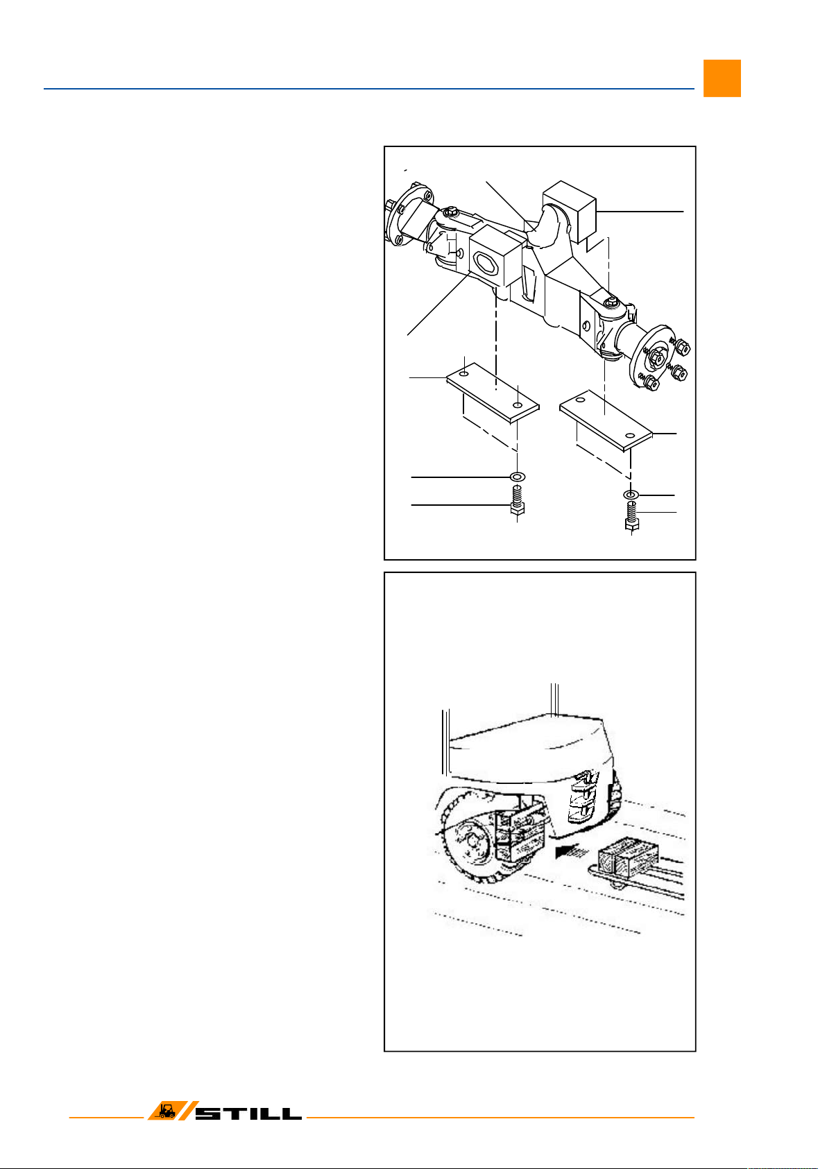
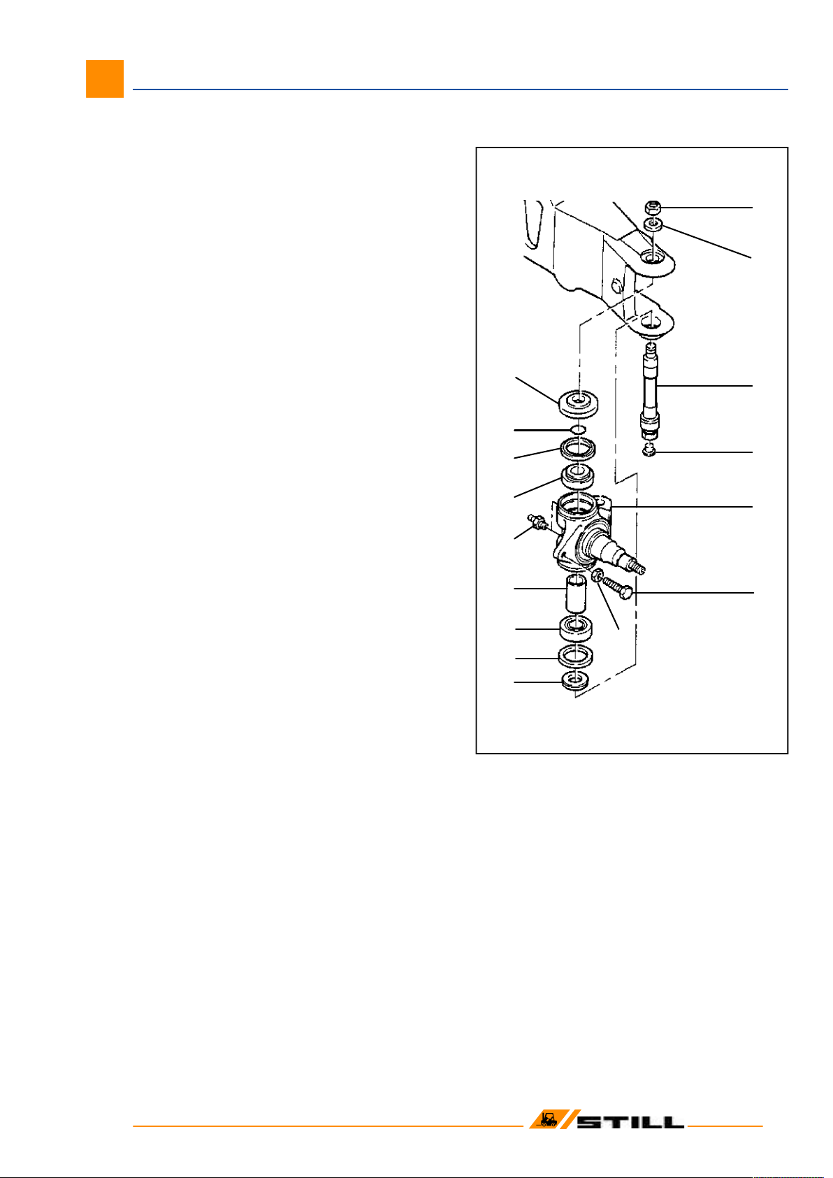
Configuration of steer axle
The articulating steer axle suspended from the
counterweight is mounted in 2 neoprene blocks. The
stub axles are supported in the axle beam on tapered
roller bearings. Steering is limited by stop screws on
the stub axles.
1 axle beam
2 fixing plates
3 hex. hd. bolt
4 spring washer
5 neoprene blocks
Steer axle removal
CAUTION: Remove steer axle only with mast in
position on the truck!
Risk of tipping!
- Apply the parking brake.
-Securely chock the front wheels to prevent
rolling of the truck.
- Slacken steer wheel nuts.
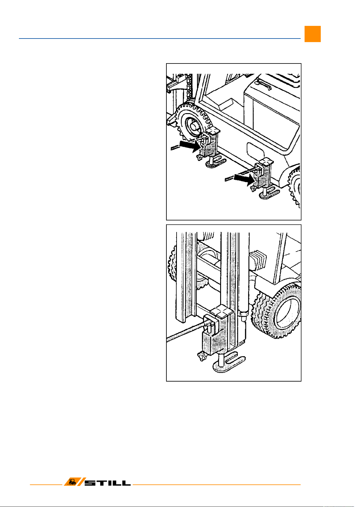
- Jack up rear of the truck at counterweight (x)
and place wooden blocks under the counter-
weight in front of the axle.
- Remove wheels.
- Disconnect the hydraulic connections at steer
cylinder.
CAUTION: Prepare for oil spillage when
disconnecting the hydraulic connections!
Catch oil in a pan of adequate capacity
and dispose of the used oil in accordance
with laws and regulations.
- Remove the 4 socket head screws which re-
tain the steer axle in place.
- Slide a hand pallet truck under the steer axle
with wooden blocks placed on the fork ends
of the hand pallet truck.
- Using a lever, drive steer axle out of roll pins
and lower the axle onto the hand pallet truck.
Steer axle installation
- Reverse the removal procedure.
- The slots of the roll pins must face the direc-
tion of forward travel.
-Torque the 4 socket heads to: MA = 195 Nm
CAUTION: Do not swap hydraulic connec-
tions left and right!
Workshop Manual 7052/56/74-76, 7054/58/77-79

12
34
6
5
9
10
7
8
11
12
02
Steer axle
5
Wheel hub - Removal and Dismantling
1 axle beam
2 stub axle
3 radial sealing ring
4 tapered roller bearing
5 wheel hub
6 roll pin
7 hub cap
8 nut
9 washer
10 tapered roller bearing
11 wheel bolt
12 ball seat nut
- Slacken ball seat nuts (12) and remove
wheel.
- Pull hub cap (7) from wheel.
- Slacken nut (8)
- Remove washer (9) with roll pin (6).
- Withdraw the hub.
- Remove radial sealing ring (3) then remove
tapered roller bearings (4) and (10) from hub.
- If necessary, drive out of wheel hub outer
races of tapered roller bearings (4) and (10).
Wheel hub - Reassembling and Installation
- Apply a smear of grease to the sealing lips of
the radial sealing ring.
- Before re-assembling the hub, repack with
grease F: cavity between inner race and
bearing cage of tapered roller bearings, and
the bearing spaces identified by an ‘x’ on the
drawing.
- To reassemble the hubs, reverse the procedure.
- Tighten nut (8) while rotating the wheel hub.
Torque loading:
MA = 145 Nm
Workshop Manual 7052/56/74-76, 7054/58/77-79

Linkskurve
= 82° +0/-2 Lenkeinschlag
Rechtskurve
1
Checking the steering angles
The steering angle a must amount to 80° - 82°.
To facilitate the measurement use the complementary
angle b for the setting. It should amount to 98° - 100°.
IMPORTANT: Ensure that the wheel lock is
limited by the stop screws (1) and not by the
cylinder stroke.
Wheel angle stop adjustment
The wheel stop angle is limited by the stop
screws (1).
- By operating on stop screws (1), set both
steering angles to 80° - 82°.
- Check opposite angles.
- Check for adequate clearance between wheels
and truck frame.
- Check that the wheel lock is not limited by
the cylinder stroke.
02
Steer axle
6
Workshop Manual 7052/56/74-76, 7054/58/77-79

4
5
6
7
8
9
11
10
12
1
2
3
13
14
15
16
02
Steer axle
7
Stub axle - Removal and Dismantling
1 nut
2 washer
3 king pin
4 plug
5 stub axle
6 hex. hd. screw
7 nut
8 spacing washer
9 wiper ring
10 tapered roller bearing
11 spacer
12 grease nipple
13 tapered roller bearing
14 wiper ring
15 O-Ring
16 spacing washer
- Remove the wheel.
- Press out the pin located between track rod
and stub axle.
- Slacken nut (1).
- Remove washer (2).
- Press the king pin (3) down through the stub
axle and remove the king pin.
- Remove the stub axle from the axle.
- Remove from the stub axle: spacing
washers, ‘O’ ring, wiper rings, tapered roller
bearings and spacer (items 8-16).
Workshop Manual 7052/56/74-76, 7054/58/77-79

1
2
3
12
14
5
4
8
7
6
10
11
13
9
Stub axle - Reassembling and Installation
1 nut
2 washer
3 king pin
4 plug
5 stub axle
6 spacing washer
7 wiper ring
8 tapered roller bearing
9 spacer
10 tapered roller bearing
11 wiper ring
12 O-Ring
13 spacing washer
14 pin
- Insert spacer (9) into the stub axle.
- Install both tapered roller bearings (8 & 10)
after having first repacked them with a
sufficient amount of FL grade grease!
- Apply a smear of FL grade grease to the
sealing lips of the wiper rings (7 & 11).
- Install wiper rings (7 & 11), ‘O’ ring (11) as well
as both spacing washers (items 13 & 6).
- Install the stub axle into the axle beam.
- Drive in the king pin (3) from below after having
first applied a light smear of oil to it.
- Fit the washer (2) into position on the king
pin.
- Install a new nut (1) and tighten to a torque of:
MA = 290 Nm
- Press the pin (14) into the track rod and secure
with roll pins.
- Install wheel.
- Lubricate the steer axle with FL grade grease.
Lubricating the steer axle
- Operate the linkage during steering.
- Using a grease gun, lubricate with FL grade
grease the fittings with which the steer axle is
equipped until a small amount of fresh grease
oozes out at the lubricating points.
02
Steer axle
8
Workshop Manual 7052/56/74-76, 7054/58/77-79

34
4
5
02
Steer axle
9
Track rod removal
The steer axle is fitted with two track rods arranged
between the steering cylinder and the two stub axles.
1 stub axle
2 piston rod
3 sealing rings
4 roll pins
5 pin
6 track rod
7 ball joint
- Remove the roll pins (4).
- Using a press, press out the pins (5).
Track rod installation
- Reverse the removal procedure.
Install pins cylinder end with a maximum press
force of
max. 21 kN
and pins stub axle end with a maximum press
force of
max. 26 kN
Workshop Manual 7052/56/74-76, 7054/58/77-79

Steering cylinder removal
– Remove track rods.
– Disconnect hydraulic connections after
having marked them for identification.
WARNING:Hydraulic oil may spill when
disconnecting lines; be prepared
for oil spillage!
– Slacken the four fixing screws (1). .
Steering cylinder installation
– Retighten the fixing screws (1).
Torque loading: MA= 210 Nm
– Reconnect hydraulic connections.
CAUTION:
Do not swap hydraulic connections!
– Install track rods.
NOTE: For steering cylinder dismantling and
reassembling refer to F.G. 06.
Lubricating the steer axle with grease
– Operate the linkage during greasing while the
steer axle is off load.
– Using a grease gun, lubricate with FL grade
grease the 8 fittings with which the steer axle
is equipped until a small amount of fresh
grease oozes out at the lubricating points.
NOTE: When lubricating the upper bearing, the
grease need not ooze out of the upper sealing
ring, it may also escape from the bottom.
02
Steer axle
10
Workshop Manual 7052/56/74-76, 7054/58/77-79

03
Workshop Manual 7052/56, 7054/58
1
Contents Page
Technical Data for Maintenance Service 1
Power Axle / Description 3
Power Axle removal 5
Power Axle installation 5
Double reduction gear and differential /
Sectional view 6
Exploded view 7
Axle housing installation 8
Half-shaft (axle shaft) removal 9
Half-shaft (axle shaft) installation 9
Wheel hub removal 10
Wheel hub installation 11

03
Workshop Manual 7052/56, 7054/58
Technical Data for Maintenance Service
3
This manual suits for next models
2
Table of contents
Other Still Forklift manuals

Still
Still EXD 18 User manual

Still
Still RCD15 User manual

Still
Still KANVAN-05 User manual

Still
Still CX-M 10 User manual

Still
Still EXV 14D User manual

Still
Still RX20 14-20 User manual

Still
Still EXV 16 User manual

Still
Still RX60-16 User manual

Still
Still FXD 20 N User manual

Still
Still RX60 25-35 User manual
Popular Forklift manuals by other brands

Xtreme Manufacturing
Xtreme Manufacturing XR1147 Operation and safety manual

Vetter
Vetter SmartFork FrontCam ATEX operating instructions

Cascade
Cascade KOOI ROLLERFORKS user manual

UniCarriers
UniCarriers WLX Series Operator's manual

Manitou
Manitou MT 1440 E3 Operator's manual

BYD
BYD EPS14P Operator's manual