TCM FB10-7 User manual

No. SEB-81BBE
TCM CORPORATION
FORKLIFT TRUCK
FB10-7
FB15-7
FB18-7
FB20-7
FB25-7
FB30-7
FB25-7LB
FB25-7V
FB30-7V
FB35-7S
Counter Balanced


No. SEB-81BBE
FOREWORD
The new TCM’s FB-7 Series battery-powered forklift trucks are provided with a newly designed
speed control system and an AC traction motor to assure high performance.
The trucks of this series are provided with a self-diagnosis function which keeps watching the
operating statuses of the main systems of the truck. If the truck has a trouble, the function detects the
trouble and displays the result of diagnosis. The maintainability is thus improved.
As for mobility, since the high capacity batteries and high power drive motors are used, the rst-class
acceleration, gradeability, and traveling performance are achieved. Controllability is also improved by
the standard equipped power steering unit.
To save power, the acceleration and traveling speeds are selectable in eight stages and made
changeable according to working conditions. Also for effective use of the battery, a regenerative device
is provided to send back counter electromotive force to the battery.
This Service Manual is intended to provide the maintenance personnel with helpful information of
the structures of the major components and with instructions on the maintenance and repair of such
components. We hope it will be much help for your servicing and maintenance operations.
February, 2008

No. SEB-81BBE

No. SEB-81BBE
SPECIFICATIONS (1)
Model FB10-7 FB15-7 FB18-7
Item
Performance
Max. load kg [lbf] 1000 [2000] 1500 [3000] 1750 [3500]
Load center mm [in.] 500 [24] ← ←
Max. lifting height mm [in.] 3000 [118.1] ← ←
Tilting angle
Fwd ° 6 ← ←
Bwd ° 12 ← ←
Free lift A mm [in.] 150 [5.9] 155 [6.1] ←
Mast tilting time (Fwd - Bwd) s 2.0 - 1.4 ← ←
Fork lifting speed
Loaded mm/s [fpm] 390 [76.8] 350 [68.9] 330 [65.0]
Unloaded mm/s [fpm] 580 [114.2] ← ←
Travel speed
Loaded km/h [mph] 14 [8.7] ← 13 [8.1]
Unloaded km/h [mph] 16 [9.9] ← ←
Gradeability
(Starting on an uphill when loaded) 1/7 ← ←
Min. turning radius
(Outermost part of truck) B mm [in.] 1700 [66.9] ← 1790 [70.5]
Min. intersecting aisle mm [in.] 1690 [66.5] ← 1730 [68.1]
Dimensions
Overall length (includ. fork) C mm [in.] 2875 [113.2] ← 2975 [117.1]
Overall width D mm [in.] 1070 [42.1] ← ←
Overall height (Overhead guard)E mm [in.] 2050 [80.7] ← ←
Overall extended height mm [in.] 4030 [158.7] ← ←
Wheel base F mm [in.] 1250 [49.2] ← 1350 [53.1]
Tread
Front wheels G mm [in.] 910 [35.8] ← ←
Rear wheels H mm [in.] 900 [35.4] ← ←
Fork overhang J mm [in.] 375 [14.8] ← ←
Rear overhang K mm [in.] 330 [13.0] ← ←
Fork size
(Length Lx Width Mx Thickness N)
mm [in.] 920 x 100 x 35 ← ←
[36.2 x 3.9 x 1.4]
Fork spacing Pmm [in.] 200 - 920 [7.9 - 36.2] ← ←
Minimum under clearance Q mm [in.] 95 [3.7] (Frame) ← ←
Tow pin height mm [in.] 390 [15.4] ← ←
Weight
Service Weight with std. batteries kg [lbf] 2650 [5842] 2710 [5976] 3000 [6600]
The values in the Performance section are given for the trucks in the Super mode.

No. SEB-81BBE
SPECIFICATIONS (2)
Model
FB20-7 FB25-7 FB25-7LB
Item FB25-7V
Performance
Max. load kg [lbf] 2000 [4000] 2500 [5000] ←
Load center mm [in.] 500 [24] ←←
Max. lifting height mm [in.] 3000 [118.1] ←←
Tilting angle
Fwd ° 6 ←←
Bwd ° 12 ←←
Free lift Amm [in.] 160 [6.3] ←←
Mast tilting time (Fwd - Bwd) s 2.7 - 2.0 ←←
Fork lifting speed
Loaded mm/s [fpm] 290 [57.1] 255 [50.2] ←
Unloaded mm/s [fpm] 510 [100.4] ←←
Travel speed
Loaded km/h [mph] 13.5 [8.4] ←13 [8.1]
Unloaded km/h [mph] 15 [9.3] ←14.5 [9.0]
Gradeability
(Starting on an uphill when loaded) 1/7 ←1/8
Min. turning radius
(Outermost part of truck) Bmm [in.] 1950 [76.8] 1970 [77.6] 2065 [81.3]
Min. intersecting aisle mm [in.] 1895 [79.6] 1905 [75.0] 1955 [76.9]
Dimensions
Overall length (includ. fork) Cmm [in.] 3315 [130.5] 3355 [132] 3460 [136]
Overall width Dmm [in.] 1150 [45.3] ←←
Overall height (Overhead guard)E mm [in.] 2095 [82.5] ←LB: 2250 [88.6]
V : 2100 [82.7]
Overall extended height mm [in.] 4030 [158.7] ← ←
Wheel base Fmm [in.] 1400 [55.1] ←1545 [60.8]
Tread
Front wheels Gmm [in.] 955 [37.6] ←←
Rear wheels Hmm [in.] 950 [37.4] ←←
Fork overhang Jmm [in.] 435 [17.1] ←←
Rear overhang Kmm [in.] 410 [16.1] 450 [17.7] 410 [16.1]
Fork size
(Length Lx Width Mx Thickness N)
mm [in.] 1070 x 122 x 40 ←←
[42.1 x 4.8 x 1.6]
Fork spacing Pmm [in.] 245 – 1020 [9.6 – 40.2] ←←
Minimum under clearance Qmm [in.] 100 [3.9] (Front axle) ←←
Tow pin height mm [in.] 440 [17.3] ←←
Weight
Service Weight with std. batteries kg [lbf] 3470 [7650] 3850 [8489] LB: 4350 [9592]
V : 4250 [9371]
The values in the Performance section are given for the trucks in the Super mode.

No. SEB-81BBE
SPECIFICATIONS (3)
Model FB30-7 FB35-7S
Item FB30-7V
Performance
Max. load kg [lbf] 3000 [6000] 3500 [7000]
Load center mm [in.] 500 [24] ←
Max. lifting height mm [in.] 3000 [118.1] ←
Tilting angle
Fwd ° 6 ←
Bwd ° 12 10
Free lift Amm [in.] 165 [6.5] 150 [5.9]
Mast tilting time (Fwd - Bwd) s 2 - 2 ←
Fork lifting speed
Loaded mm/s [fpm] 290 [57.1] 230 [45.3]
Unloaded mm/s [fpm] 490 [96.5] 400 [78.7]
Travel speed
Loaded km/h [mph] 13.5 [8.4] 12.5 [7.8]
Unloaded km/h [mph] 15 [9.3] 14 [8.7]
Gradeability
(Starting on an uphill when loaded) 1/8 ←
Min. turning radius
(Outermost part of truck) Bmm [in.] 2140 [84.3] 2360 [92.9]
Min. intersecting aisle mm [in.] 2050 [80.7] 2250 [88.6]
Dimensions
Overall length (includ. fork) Cmm [in.] 3580 [141] 3835 [151.0]
Overall width Dmm [in.] 1225 [48.2] 1380 [54.3]
Overall height (Overhead guard)E mm [in.] 2190 [86.2] ←
V: 2100 [82.7]
Overall extended height mm [in.] 4260 [167.7] 4265 [167.9]
Wheel base Fmm [in.] 1600 [63.0] 1800 [70.9]
Tread
Front wheels Gmm [in.] 1000 [39.4] 1140 [44.9]
Rear wheels H mm [in.] 950 [37.4] ←
Fork overhang Jmm [in.] 480 [18.9] 530 [20.9]
Rear overhang K mm [in.] 430 [16.9] ←
Fork size
(Length Lx Width Mx Thickness N)
mm [in.] 1070 x 125 x 45 1070 x 150 x 50
[42.1 x 4.9 x 1.8] [42.1 x 5.9 x 2.0]
Fork spacing Pmm [in.] 250 – 1090 [9.8 – 42.9] 300 – 1200 [11.8 – 47.2]
Minimum under clearance Q mm [in.] 110 [4.3] (Rear axle) ←
Tow pin height mm [in.] 475 [18.7] ←
Weight
Service Weight with std. batteries kg [lbf] 4660 [10275] 5590 [12325]
The values in the Performance section are given for the trucks in the Super mode.

No. SEB-81BBE
No. SEB-81BBE
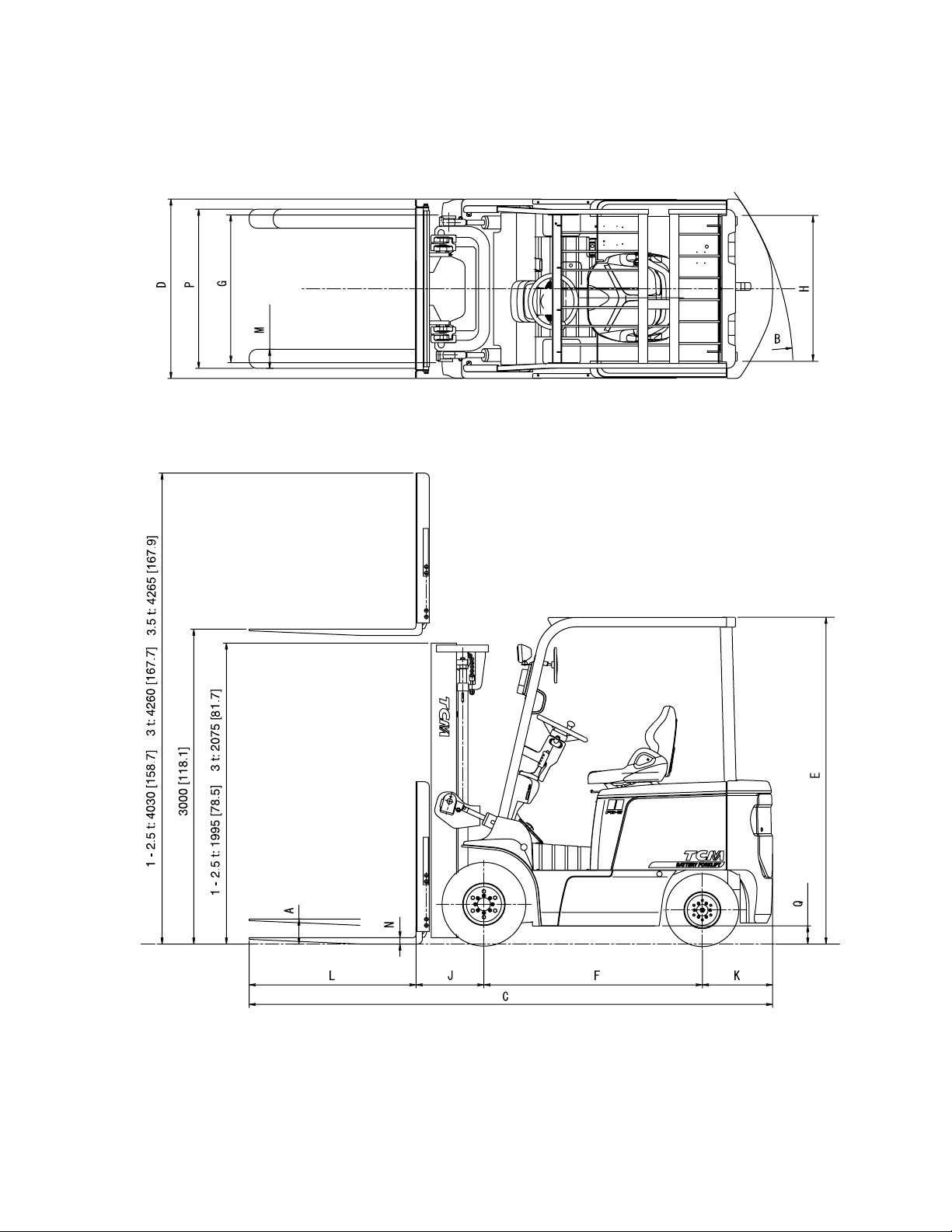
Fig. 1 Overall Dimensions
Unit: mm [in.]

No. SEB-81BBE

No. SEB-81BBE
CONTENTS
1. BATTERY AND CHARGER .............................................................................................. 1
1.1 GENERAL DESCRIPTION....................................................................................................... 2
1.1.1 BATTERY ............................................................................................................................ 2
1.1.2 CHARGER........................................................................................................................... 4
1.1.3 CHARGING PROCEDURES.............................................................................................. 13
1.1.4 CHARGER OPERATION.................................................................................................... 15
2. MOTORS .................................................................................................................................... 17
2.1 GENERAL DESCRIPTION....................................................................................................... 17
2.1.1 DRIVE MOTOR .................................................................................................................. 17
2.1.2 PUMP MOTOR.................................................................................................................... 21
2.2 MAINTENANCE ....................................................................................................................... 23
2.2.1 DRIVE MOTOR .................................................................................................................. 23
2.2.2 PUMP MOTOR.................................................................................................................... 27
3. CONTROL SYSTEM ............................................................................................................. 29
3.1 GENERAL DESCRIPTION....................................................................................................... 29
3.1.1 INVERTER .......................................................................................................................... 29
3.1.2 ACCELERATOR PEDAL.................................................................................................... 34
3.1.3 INTERLOCK SYSTEM ...................................................................................................... 35
3.1.4 BACK-DOWN ALARM SYSTEM ..................................................................................... 36
3.2 MAINTENANCE ....................................................................................................................... 37
3.2.1 TROUBLESHOOTING GUIDE.......................................................................................... 37
4. DRIVE UNIT AND DRIVE AXLE ..................................................................................... 55
4.1 GENERAL DESCRIPTION....................................................................................................... 55
4.1.1 DRIVE UNIT ....................................................................................................................... 55
4.1.2 DRIVE AXLE ...................................................................................................................... 59
5. BRAKE SYSTEM ................................................................................................................... 63
5.1 GENERAL DESCRIPTION....................................................................................................... 63
5.1.1 BRAKE PEDAL................................................................................................................... 63
5.1.2 MASTER CYLINDER ........................................................................................................ 65
5.1.3 WHEEL BRAKE.................................................................................................................. 66
5.1.4 PARKING BRAKE LEVER ................................................................................................ 68
5.2 MAINTENANCE ....................................................................................................................... 71
5.2.1 DISASSEMBLING WHEEL BRAKE................................................................................. 71
5.2.2 INSPECTION....................................................................................................................... 73
5.2.3 REASSEMBLING WHEEL BRAKE .................................................................................. 74
5.2.4 OPERATION TEST OF AUTOMATIC CLEARANCE ADJUSTER ................................. 76

No. SEB-81BBE
5.2.5 ADJUSTING BRAKE PEDAL............................................................................................ 77
5.2.6 TROUBLESHOOTING GUIDE.......................................................................................... 78
6. STEERING SYSTEM ............................................................................................................ 79
6.1 GENERAL DESCRIPTION....................................................................................................... 79
6.1.1 OUTLINE OF STEERING SYSTEM ................................................................................... 80
6.1.2 STEERING GEARBOX........................................................................................................ 81
6.1.3 ACTUATOR .......................................................................................................................... 84
6.1.4 REAR AXLE ......................................................................................................................... 84
6.1.5 ADJUSTING PRELOAD OF REAR WHEEL BEARING ................................................... 88
6.1.6 ASSEMBLING WHEEL ....................................................................................................... 89
6.2 MAINTENANCE ........................................................................................................................ 90
6.2.1 MAINTENANCE OF ACTUATOR ...................................................................................... 90
6.2.2 MAINTENANCE OF STEERING BEARBOX.................................................................... 93
7. HYDRAULIC SYSTEM ........................................................................................................ 103
7.1 GENERAL DESCRIPTION ........................................................................................................ 103
7.1.1 MAIN PUMP ......................................................................................................................... 104
7.1.2 CONTROL VALVE ............................................................................................................... 104
7.1.3 HYDRAULIC OIL TANK..................................................................................................... 108
7.1.4 LIFT CYLINDER .................................................................................................................. 109
7.1.5 FLOW REGULATOR VALVE .............................................................................................. 114
7.1.6 TILT CYLINDER .................................................................................................................. 116
7.2 MAINTENANCE ........................................................................................................................ 118
7.2.1 MAINTENANCE OF PUMP ................................................................................................ 118
7.2.2 TRIAL RUN........................................................................................................................... 130
7.2.3 TROUBLESHOOTING GUIDE ........................................................................................... 131
8. LOAD HANDLING SYSTEM ............................................................................................ 133
8.1 GENERAL DESCRIPTION ........................................................................................................ 134
8.1.1 OUTER AND INNER CHANNELS ..................................................................................... 134
8.1.2 CARRIAGE ........................................................................................................................... 136
8.1.3 LOCATIONS OF ROLLERS ................................................................................................ 139
8.2 MAINTENANCE ........................................................................................................................ 142
8.2.1 ADJUST LIFT CYLINDER ROD WITH SHIMS ................................................................ 142
8.2.2 ADJUSTING HEIGHT OF CARRIAGE .............................................................................. 142
8.2.3 PROCEDURE FOR REPLACING ROLLERS AT CARRIAGE SIDE................................ 144
8.2.4 PROCEDURE FOR REPLACING ROLLERS AT MAST SIDE ......................................... 146
8.2.5 PROCEDURE FOR ADDING OR SUBTRACTING SHIMS.............................................. 147
9. ELECTRIC WIRING .............................................................................................................. 149
1. BATTERY AND CHARGER
- 1 -
1. BATTERY AND CHARGER (OPTION)
The description in this section applies to our optional batteries and chargers. For other types of
batteries and chargers, refer to their respective instruction manuals. The description of the VTM unit
applies to all the trucks because the VTM unit is standard equipment.
Truck model
FB10-7 FB15-7 FB20-7 FB25-7
Item FB18-7
Battery
Capacity 330AH/5h 400AH/5h 450AH/5h 565AH/5h
Name VSDX330M VSDX440M VSDX450M VSDX565HM
Voltage 48 V
Specic gravity of
electrolyte 1.280
Weight 650 kg 695 kg 830 kg 915 kg
Charger
Type Truck-mounted type, 3-phase AC semiconstant voltage charger
Rated power 6.0 kVA 8.5 kVA
Rated current 17 A 24 A
Power supply voltage
380 / 440 V
Applicable battery
capacity 320 - 500 AH/5h 450 - 700 AH/5h
Output
Voltage 51 - 64 V
Current 80 - 20 A 115 - 29 A
Truck model
FB25-7LB FB25-7V FB30-7 FB35-7S
Item FB30-7V
Battery
Capacity 935AH/5h 865AH/5h 450AH/5h 545AH/5h
Name VSF935 VSF865 VSDX450MZ VSDX545MH
Voltage 48 V 72 V
Specic gravity of
electrolyte 1.280
Weight 1450 kg 1350 kg 1130 kg 1285 kg
Charger
Type
Truck-mounted type, 3-phase AC semiconstant voltage charger
Rated power 12 kVA
Rated current 34 A
Power supply voltage
380 / 440 V
Applicable battery
capacity 320 - 500 AH/5h 450 - 700 AH/5h
Output
Voltage 51 - 64 V 76.5 - 96 V
Current 160 - 40 A 105 - 26 A
1. BATTERY AND CHARGER
- 2 -
1.1 GENERAL DESCRIPTION
1.1.1 BATTERY
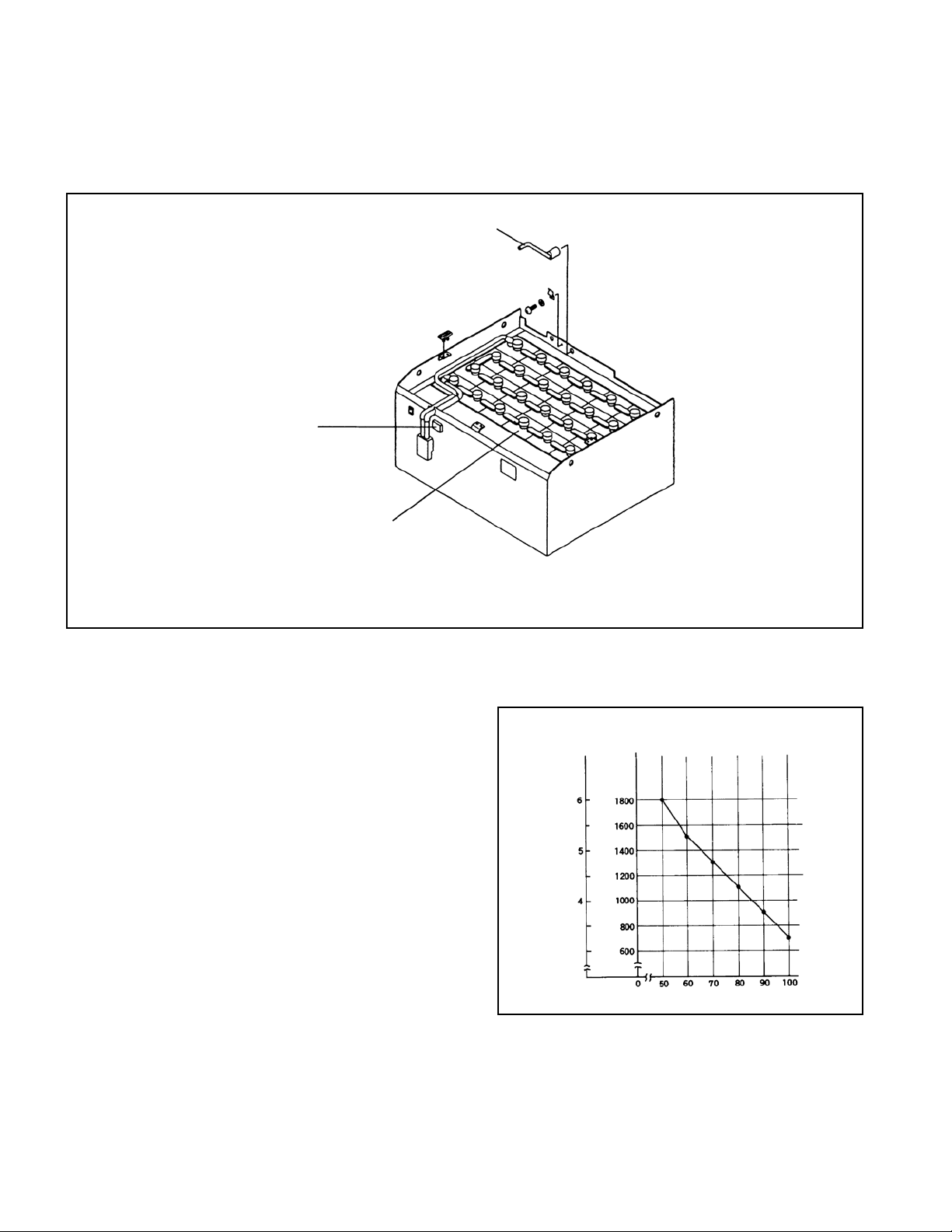
The battery unit consists of twenty-four 2-volt battery cells connected in series. Figure 1.1 shows its
construction.
(1) Battery care
The most important point in battery care is to
prevent overdischarge. The deeper the battery
discharges, the shorter its life becomes (See Fig. 1.2).
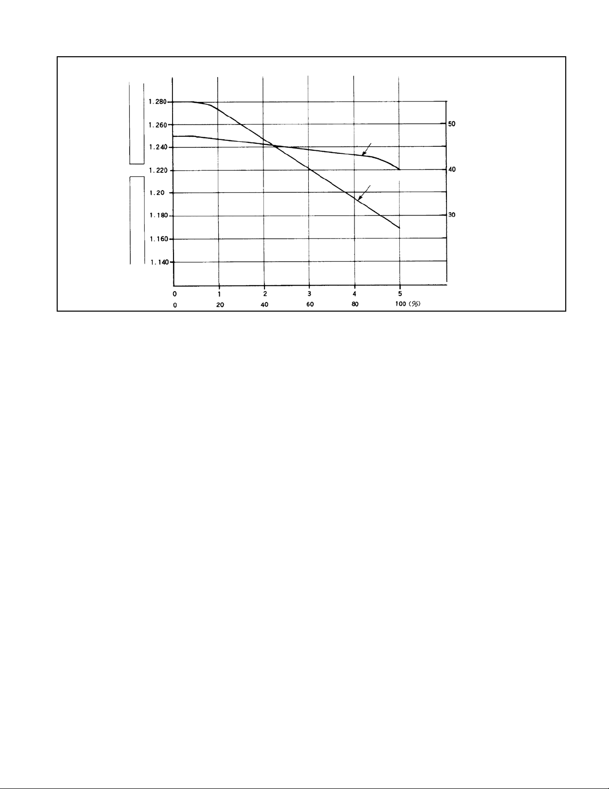
The approximate depth of discharge can be known
by measuring the specic gravity of the electrolyte
(See Fig. 1.3)
Check the level of electrolyte every ten days.
Add distilled water if the level is found lower than
the specied level before charging the battery.
Fig. 1.2
Relation Between Depth of Discharge
and Service Life (Example)
Service life
Cycles of
charge and
discharge
Depth of discharge (%)
BATTERY CELL WITH
ELECTROLYTE LEVEL SENSOR
LOCK PIN
ELECTROLYTE
LEVEL INDICATOR
Fig. 1.1
Battery Unit
Note: The sketch shows a 48-volt battery unit. The 72-volt battery unit has 36 battery cells.
1. BATTERY AND CHARGER
- 3 -
(2) Charging the battery
When discharged, the battery should be recharged as soon as possible. Leaving the battery discharged
for a long time may cause sulfation, which will result in a drop of the battery performance.
If the battery is kept out of service for a long time, it should be thoroughly charged before put in
storage. An additional charge is also required once a month.
Do not leave a fully discharged battery longer than a day as it is. Be sure to recharge it as soon as
possible.
If the amount of discharge is considered to be small, measure the specic gravity of the electrolyte.
If lower than 1.260, recharge the battery.
Equalizing charge is required if the specic gravity varies among the cells by the amount of 0.020 or
larger. Equalizing charge is normally needed between one to four times a month.
If the specic gravity variation is not made smaller by equalizing charge, specic gravity adjustment
will be required.
Giving an equalizing charge more times than necessary will overcharge the battery, and its service
life will be shortened.
For a truck-mounted type charger, a microcomputer determines when an equalizing charge is required
and carries out equalizing charge automatically.
[Cautions on Charging the Battery]
(1) Do not start charging the battery if the electrolyte temperature is higher than 50°C. Leave the
battery for a while until the temperature goes low. Then charge it.
(2) Overdischarge or overcharge raises the electrolyte temperature. While charging the battery, be sure
to keep the battery cover fully open in order to let the generated gas and heat get out.
[Specic Gravity Correction According to Temperature]
The specic gravity of the electrolyte varies as the electrolyte temperature changes. The specic
gravity is generally based on the electrolyte temperature of 20°C. Therefore, if the specic gravity is
measured at the electrolyte temperature if other than 20°C, correct it using the following formula:
S20 = St + 0.0007 (t – 20)
where S20 ............specic gravity for 20°C
St...............specic gravity measured at t
t.................electrolyte temperature measured.
(Discharge rate)
Fig. 1.3 An Example of Specic Gravity Drop
Specic gravity
(at 20°C)
Usable
Alert !
Overdischarge
Voltage (V)
Voltage
(Discharge duration)
Specic gravity

1. BATTERY AND CHARGER
- 4 -
1.1.2 CHARGER
The charger mounted on the truck is a computer-controlled, semiconstant-voltage type consisting of a
transformer, diodes, an operation panel, and a VTM unit.
INSULATION TUBE BAND
INSULATION TUBE
BAND
SECONDARY WIRE CONTACTOR VTM UNIT
PRIMARY WIRE THERMAL RELAY
SECONDARY WIRE CONTACTOR VTM UNIT
PRIMARY WIRE THERMAL RELAY
CONNECTION OF PRIMARY
WIRE (PORTION NOT USED)
CONNECTION OF
SECONDARY WIRE
Thermal relay current settings
Transformer model Setting (A)
M80B 18
M80C 11
M80D
M105B 37
M105C 20
M105D
M115B 29
M115C 15
M115D
Note: The charger for the FB30 and FB35 series is not shown . (It is almost the same design as that for the FB20 series.)
Fig. 1.4

1. BATTERY AND CHARGER
- 5 -
(1) Transformer
The transformer is located at the right side frame and converts input voltage to a voltage of the level
necessary for charging the battery.
There are three taps provided with a 10-volt difference from one to another. Make a selection among
them at the input side according to the input voltage level.
Fig. 1.5 Transformer
PRIMARY WIRE
■
Transformer tap changing
The supply voltage varies with the periods of time. Change therefore the taps from one to
another according to the average of supply voltages which to charger receives for the period of
time during which the battery is normally charged.
GROUND WIRE (GREEN)
SECONDARY WIRE
Supply Voltage (Average) Symbol
380 V 440 V of Tap
50 Hz 60 Hz 50 Hz 60 Hz
350 - 370 360 - 380 400 - 420 410 - 430 L
370 - 390 380 - 400 420 - 440 430 - 450 M
390 - 410 400 - 420 440 - 460 450 - 470 H
Note 1: Change all the three
phases as a set.
Note 2: Give a terminal cap
to each of the taps
which are not used, and
fix them by the wire
binder.
1. BATTERY AND CHARGER
- 6 -
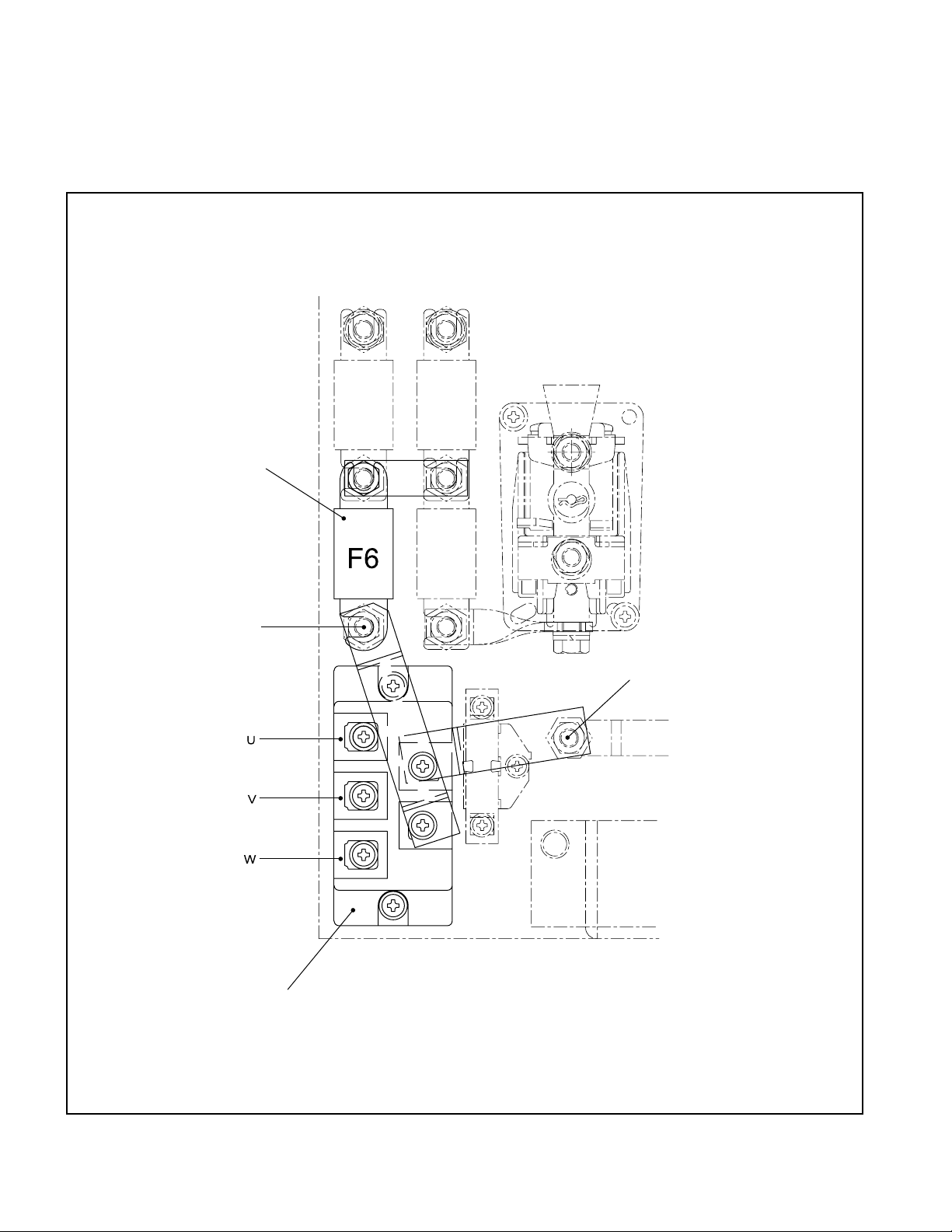
(2) Diode
The diode, installed on the speed controller, is a 3-phase, full-wave rectication type which converts
AC to DC.
The current rectied by the diode ows through the fuse F6 to charge the battery.
FUSE (130A)
(FB25-7LB, FB25-7V: 200A)
CHARGING DIODE
POSITIVE
TERMINAL
NEGATIVE TERMINAL
Fig. 1.6 Diode
1. BATTERY AND CHARGER
- 7 -
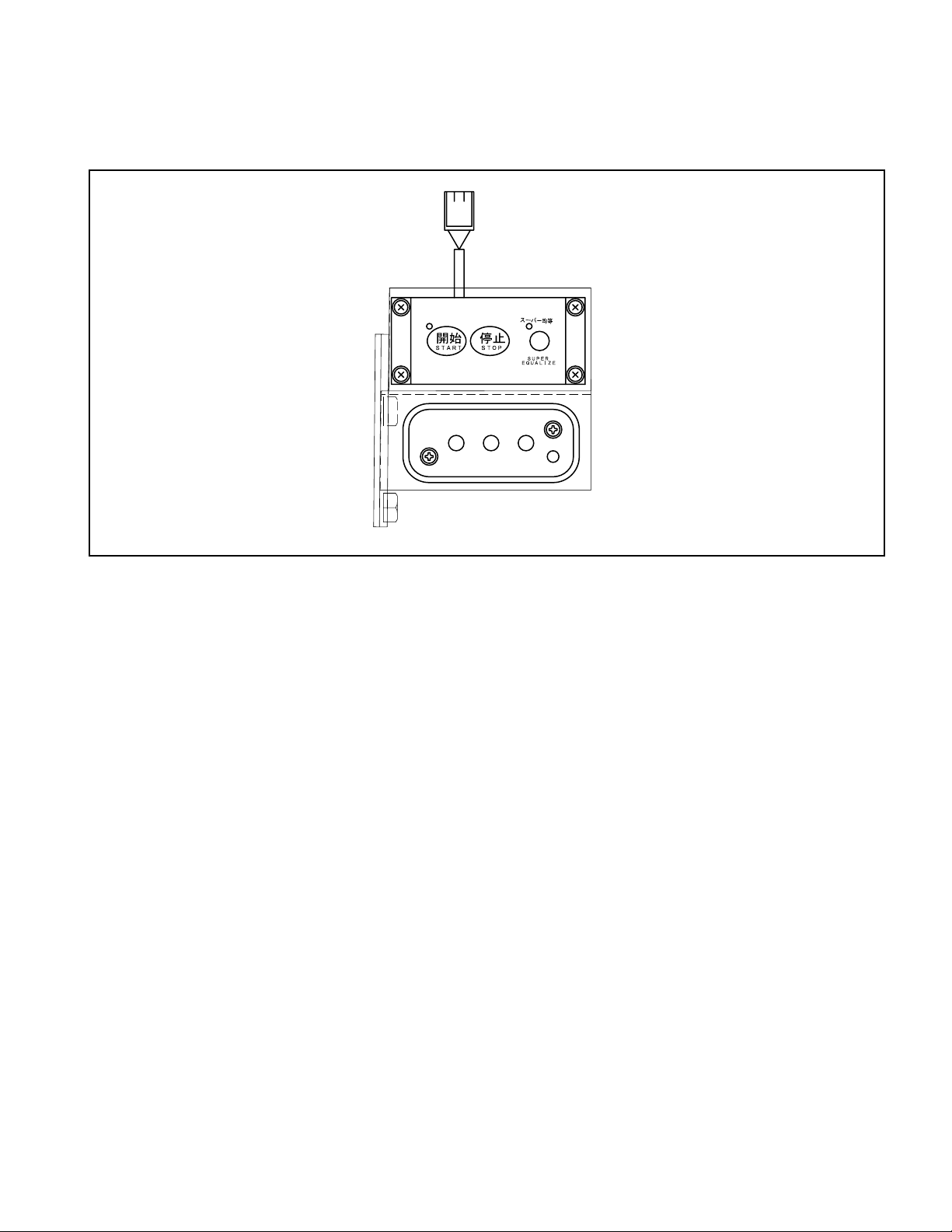
(3) Operation panel
The operation panel is located on the left side of the cabinet and equipped with a charger control
switches, lamps and service power outlet.
(4) VTM unit
The VTM unit is installed inside the right side frame. It sets the charging time for the battery
assembly by the signal from the operation panel.
■
Major features of VTM unit
①
Optimal charge according to battery’s state of charge
Conventionally, overcharge might occur when not so an exhausted battery is charged. On this
charger, the microprocessor judges the battery’s state of charge and changes the normal timer setting
within a specied range for optimal charge.
This setting voltage is compensated properly to provide optimal charge even if there are temperature
changes.
②
Super equalizing charge
The microprocessor counts the charging time and automatically provides equalizing charge when a
specied time is reached. The time setting for super equalizing charge is preset properly according
to the ambient temperature after temperature compensation. This function saves the trouble of the
operator’s bothering to press the equalizing charge button.
③
In case of power failure while charging
Unless power failure continues longer than 120 hours, battery charging is normally completed.
■
VTM unit
The VTM is mainly composed of its timer function. The microprocessor of the VTM unit determines
and sets an optimal duration of charging after checking the state of the battery.
Fig. 1.7 Operation Panel

1. BATTERY AND CHARGER
- 8 -
The VTM unit has two timers: One is called rst timer and the other second timer. It is the rst timer
on which the microprocessor sets the charging time (4 hours maximum).
The time to be set on the second timer is 15 hours for normal charging. If a single charging continues
longer than that duration, charging is treated as an abnormal termination. The lamp on the operation
panel then blinks and the display gives a message to inform the operator of that abnormal termination.
Data of past battery charge are stored in memory of the VTM unit. Based on these data, the
microcomputer judges whether or not the battery needs equalizing charge. The data store in memory
are:
* The changes in battery voltage and electrolyte temperature and voltage settings of charge sessions
performed within the last 40 hours
(94 hours for trucks manufactured earlier than January 31, 2004)
* The total charging hours, and the total hours during which the battery was connected to the charger.
* The number of times the battery got an equalizing charge.
* The number of times charging was terminated by the rst timer.
* The number of times charging was terminated by the second timer.
* The number of times charging was stopped incomplete. (The number of times the stop button is
pressed.)
The VTM unit is also provided with an LED display on its printed circuit board. The LED display
is used for showing various data in connection with the charger/battery so that it helps the operator be
informed of adjustment data or the status of the charger according to the position of the setting switch
located on the printed circuit board.
Fig. 1.8 VTM Unit (for trucks manufactured earlier than January 31, 2004)
Other manuals for FB10-7
1
This manual suits for next models
9
Table of contents
Other TCM Forklift manuals


Popular Forklift manuals by other brands

Noblelift
Noblelift FE4P16-20 Q Series Operation manual

logitrans
logitrans EHS Stainless 1000/1400 instruction manual

Jungheinrich
Jungheinrich DFG 540 operating instructions

logitrans
logitrans Level Control LC4 manual

Still
Still R70-40T operating instructions

albutt
albutt F100 INSTRUCTION MANUAL AND PARTS CATALOGUE


