TCO ICon Pro User manual

ICon Pro - user manual
TCO Sp. z.o.o.
Tyniecka 126C, 30-376 Krakow, Poland

2
Original user manual, written in the English Language
TCO Sp. z o.o.
Tyniecka 126C, 30-376 Krakow, Poland
T +48 12 268 3218
I www.iconairhealer.eu
Model: ICon Pro
Date: 25/03/2020
Product code: ICon.2020.01…..
Version: 1.3
Distributor address and contact data for replacement filters:

3
Preface
Congratulations, you have just become the owner of the ICon Air Healer with the newest and unique
technology in air treatment. Your ICon Pro will improve your indoor air quality in a way no other unit
can. This will improve your life standard and safety.
Please read this manual carefully before you start using the ICon Pro. This will help you to enjoy the
results ICon Pro delivers, for a long time.
The ICon Pro is easy to use when you follow the instructions. Please read the user manual carefully.
Become familiar with the correct operation and maintenance procedures. Store the manual in a safe
place. The manual is an essential part of the ICon Pro and must be handed over to the new owner
upon resale or exchange. Each ICon Pro has a unique identification number that can be found on the
back side of the unit, in the left lower corner. Your TCO partner needs this number when you order
parts.
When this manual refers to “the manufacturer” this means: TCO Sp. z o.o. in Kraków, Poland. When
this manual mentions “the partner”, your local TCO resell and support service partner is referred to.
Purpose of the user manual
The purpose of the user manual is to provide the user with information during the life of the ICon Pro
in such a way that the ICon Pro is used correctly, efficiently and safely, even in the event of
reasonably foreseeable misuse.
The user manual contains instructions regarding:
•Personal operator safety
•Intended and non-intended use of the ICon Pro
•Instructions for daily use
•Maintenance instructions
•Storage conditions
•Disposal of the ICon Pro
These instructions must be considered to avoid risks that could lead to physical and/or material
damage.
Target audience
This user manual is intended for operators of the ICon Pro and their supervisors, as well as partners
and importers.
Operators of the ICon Pro
The ICon Pro may only be operated by a person who:
•has correctly read and understood the instructions in this manual;
•is trained by an experienced operator who has read and understood the instructions in this
manual.

4
Reading guide
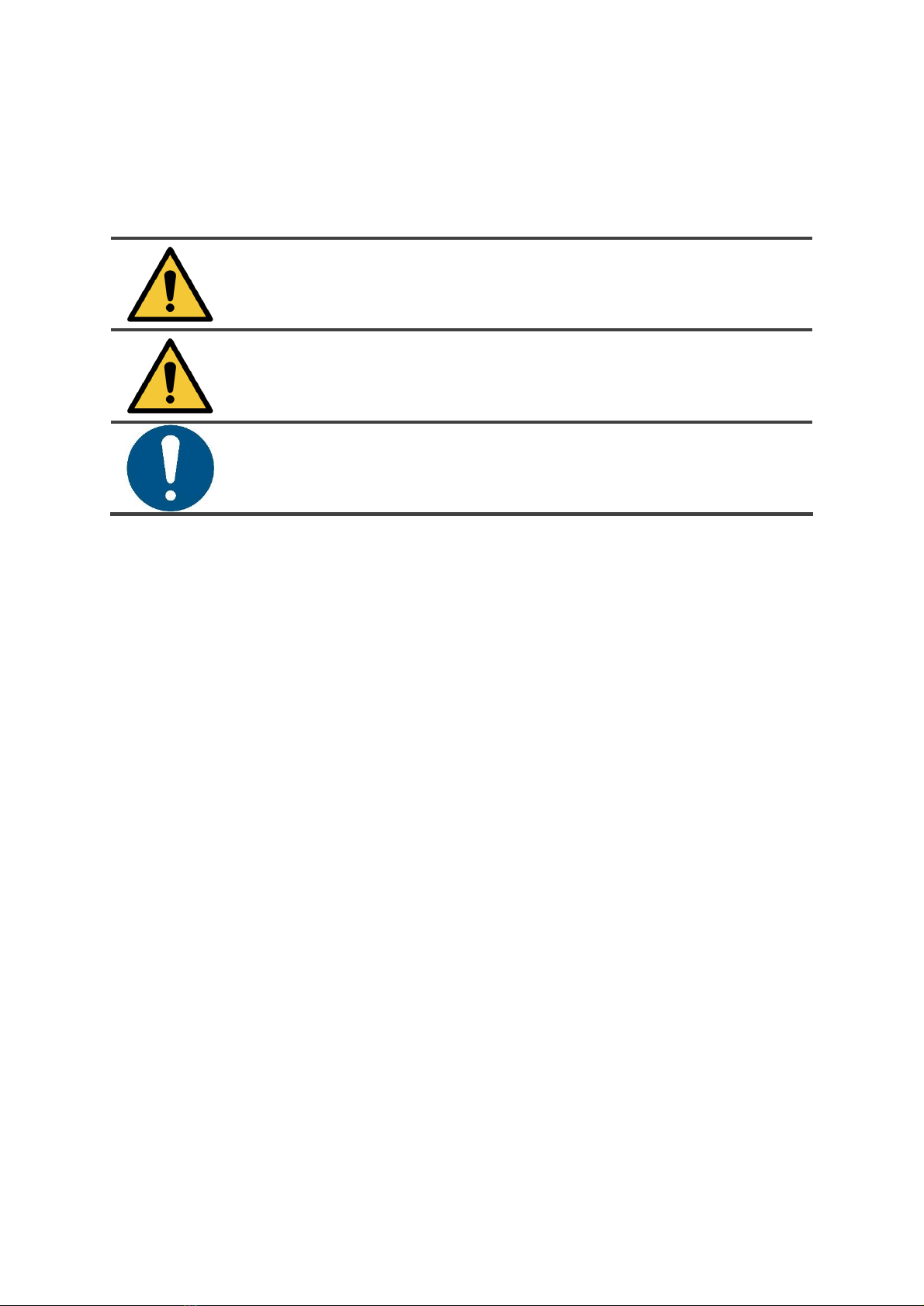
The following symbols and terms are used throughout this manual to alert the reader to
safety issues and important information:
Symbol
Term
Explanation
WARNING
Indicates a hazardous situation which, if the safety
instructions are not followed, can lead to injuries of the
operator or bystanders, light and/or moderate damage
to the product or the environment.
CAUTION
Indicates a hazardous situation which, if the safety
instructions are not followed, can lead to light and / or
moderate damage to the product or the environment.
ATTENTION
Indicates a liability situation, where the manufacturer
or its partners and affiliates cannot be held accountable
for damages caused by non-compliance.

5
Content
Preface .................................................................................................................................................................... 3
Purpose of the user manual.................................................................................................................................... 3
Target audience ...................................................................................................................................................... 3
Operators of the ICon Pro ....................................................................................................................................... 3
Reading guide.......................................................................................................................................................... 4
1Introduction.................................................................................................................................................... 7
1.1 Intended use of the product.................................................................................................................. 7
1.2 Non-intended use of the product.......................................................................................................... 8
1.3 Lifespan.................................................................................................................................................. 8
1.4 Modifications......................................................................................................................................... 8
1.5 Specifications......................................................................................................................................... 9
1.6 Warranty.............................................................................................................................................. 10
1.7 Identification ....................................................................................................................................... 10
2Description ................................................................................................................................................... 11
2.1 Working principle ................................................................................................................................ 12
3Safety............................................................................................................................................................ 13
3.1 General safety instructions.................................................................................................................. 13
3.2 Machine orientation............................................................................................................................ 13
4Transport and storage.................................................................................................................................. 13
5Assembly and installation............................................................................................................................. 14
5.1 Unboxing.............................................................................................................................................. 14
5.1.1 Unboxing your ICon Pro .................................................................................................................. 15
6Operation ..................................................................................................................................................... 16
6.1 Before you start................................................................................................................................... 16
6.2 Main power on/off .............................................................................................................................. 16
6.3 Boost function ..................................................................................................................................... 17
6.4 Control panel ....................................................................................................................................... 18
6.4.1 Using the control panel ................................................................................................................... 18
6.4.2 Fan menu......................................................................................................................................... 19
6.4.3 Schedule menu................................................................................................................................ 20
6.4.4 Sensors menu.................................................................................................................................. 21
6.4.5 Lamps menu.................................................................................................................................... 22
6.4.6 Settings menu.................................................................................................................................. 23
6.4.7 Status menu .................................................................................................................................... 24
7Maintenance ................................................................................................................................................ 25
7.1 Replace the pre-filter........................................................................................................................... 25

6
7.2 Replace the main HEPA filter............................................................................................................... 27
7.3 Recommended additional cleaning ..................................................................................................... 28
7.4 Ordering replacement filters ............................................................................................................... 28
7.5 Service interval UV-lamps.................................................................................................................... 29
8Trouble shooting .......................................................................................................................................... 30
9Decommissioning and disposal .................................................................................................................... 31
10 Attachments................................................................................................................................................. 32
10.1 Technical specifications ....................................................................................................................... 32
General specifications .................................................................................................................................. 32
Performance................................................................................................................................................. 32
Other features.............................................................................................................................................. 32
10.2 CE certificate........................................................................................................................................ 33

7
1Introduction
The ICon Pro is a safe and easy to use machine. This manual helps you to get started and explains the
operation and maintenance procedure. You will be surprised how fast and effective the ICon Pro is in
improving the indoor air quality. But remember, NO unit in the world is able to remove 100% of all
contaminants from the air. The quality of healed air delivered by ICon Pro is unconquerable.
Indoor air quality refers to the air quality within buildings and structures, focusing on health and
comfort of building occupants. In general it is what we experience as the temperature, humidity, good
or bad ventilation and concentration of different air contaminants.
It is scientifically proven that the indoor air quality can be five to ten times worse than outdoor air
quality, especially with regard to airborne chemicals and microbiological contamination.
There are three main contaminants’ groups:
•particulate matter - air suspended particles (commonly known as PM level);
•VOC (volatile organic compounds) - gases emitted from solid or liquid sources, which include
a wide range of chemicals, some with short term or long term effect on health and human
body;
•(micro) biological contamination - includes bacteria, viruses and molds.
Only by eliminating all three groups of contaminants the air we breathe is safe and healthy. We call it
healed air.
The best way to improve your indoor air quality is to:
•reduce the contamination at its’s source, for example by reducing the use of chemicals
(including cleaning chemicals), using proper filters in vacuum cleaners and reducing cross
contamination between rooms and buildings;
•improve ventilation (often a difficult and expensive solution, especially in modern buildings
with complex HVAC systems);
•use an air cleaner. The ICon Pro is one of the very few air cleaners that deliver really pure air.
We call it healed air, since it is perfectly purified and healthy.
TCO continuously improves all their products based on user experience and feedback. Any deviations
between the texts and/ or images from the manual and your ICon Pro can therefore arise from the
difference in model or from possible changes due to continuous development and innovation.
1.1 Intended use of the product
The ICon Pro is developed around the unique FS-ACT® technology (USA, Europe and other countries
patent protected) which targets all three groups of contaminants, delivering really clean air.
FS-ACT®translates into Full Spectrum Air Cleaning Technology. Our system is the first and only on the
market which works truly as a Neutralize &Collect technology. The ICon Pro does not just filter the air.
It also neutralizes all living organisms, brakes down and eliminates harmful gases and, before air outlet,
collects all particles and what is left from microbes on a high grade filter.
•The ICon Pro is for indoor use only, do not use it outdoors.
•The machine is designed for commercial use in medium to large spaces (up to 500 m2).
Of course the actual space coverage will depend on contamination level. In a specific
situation with one ICon Pro unit you will be able to heal the air on a smaller space or you may
be forced to use two units.

8
1.2 Non-intended use of the product
WARNING
Non-intended use can have consequences for the safety of operators and bystanders
and will void the warranty on the product.
Do not use the ICon Pro:
•outdoors;
•in the proximity of high humidity sources, like indoor air humidifiers, spa area near the indoor
fountains;
•in industrial applications with a high dust level since this will limit the efficiency and may
damage the unit;
•without the use of a grounded 230/110V power source;
•with a damaged power cord;
•in areas or rooms with a risk of explosion;
•with clogged air inlet and filters.
1.3 Lifespan
CAUTION
ICon Pro is designed to work almost maintenance free for a long time. You should not
need to contact an authorized TCO partner before 4 years of running ICon Pro 24/7. But
should error codes happen too often, always do contact your supplier to ensure long
and trouble free operations. When run in a 24/7 mode, you will have to replace certain
parts , this operation is possible and doable only by your specialized service provider.
1.4 Modifications
It is not permitted to make modifications to the design and construction of the ICon Pro without
consultation and written permission from the manufacturer. This affects the warranty, see section
1.6 Warranty, and may be the reason of potentially risky and dangerous situations.

9
1.5 Specifications
Figure 1
Product (body unit):
1273*684*334 mm
Weight:
72 kg
Control panel on front of unit:
yes
Transport wheels:
yes

10
1.6 Warranty
The ICon Pro should only be used with the materials supplied. Using alternative supplies may cause
damage to the ICon Pro and may cause a risk to the operator. The use of alternative supplies voids
manufacturer's warranty. Standard manufacturers warranty period is 24 months. Warranty
conditions you will find on www.iconairhealer.eu/resources.
1.7 Identification
Each ICon Pro has a unique identification number that can be found on the back side of the unit, in
the left lower corner. Your TCO partner needs this number when you order parts.
Explanation type plate:
Product type: ICon Pro
Serial number: ICon.2020.01…..
Power supply and capacity: AC110/230V 250W
Manufacturer: TCO Sp. z o.o.
Country of assembly: Poland
Figure 2

11
2Description
The ICon Pro combines state-of-the-art air purifying technologies in one, easy to set up stand-alone
unit. The ICon Pro consists of:
Figure 3
1. LED indicators.
2. Display.
3. Operation knob.
4. Locking knobs of main HEPA filter compartment lid.
5. Main HEPA filter compartment. Attached to the inside of the compartment panel you will find
a 2.5 Allen wrench, to be used for opening the panel of the pre-filter compartment.
6. Neutralization chamber panel. (only to be accessed by qualified service provider).
7. Power cable.
8. Power cable socket.
9. Main power on/off switch.
10. Boost function on/off switch.
11. RJ ethernet connection socket.
12. Air inlets.
13. Air outlet.
14. Caster wheels brakes.
15. Caster wheels.
16. Pre-filter compartment.

12
2.1 Working principle
The polluted air enters the air inlets at the front
and bottom of the unit (Figure 4, pos. 5).
The air passes through the custom designed pre-
filter (Figure 4, pos. 4). The pre-filter filters out
larger particles and heavy dust. The layers of
activated carbon in the pre-filter provide basic
absorption of volatile organic compounds.
The neutralization chamber (Figure 4, pos. 3) is
equipped with complex and sophisticated
technology (patented). A combination of UV light
and other technologies, takes care of the volatile
organic compounds and micro-biological
contamination.
The decontaminated air finally passes through a
high grade, custom made main HEPA filter
(Figure 4, pos. 1). This filter ensures proper
filtration of the smallest particles (even smaller
than 0,3µ). The clean air leaves the unit through
the air outlet (Figure 4, pos. 6) on the front of the
ICon Pro unit.
1. HEPA filter.
2. Fan.
3. Neutralizing chamber.
4. Carbon pre-filter.
5. Contaminated air inlets.
6. Healed air outlet.
7. Dust and VOC sensors.
The ICon Pro is equipped with:
•a 110V/230V power supply unit;
•a powerful air fan;
•sensors for measuring the level of volatile organic particles in the outgoing air, the pressure
drop on the main filter and the level of dust in the outgoing air;
•safety switches (so called kill switches) on the panels of main HEPA filter and pre-filter
compartments;
•RJ socket for ethernet connection (for trained user only).
ATTENTION
It is advisable that the RJ ethernet connection is used by IT advanced users only
and/or by trained operators. Ask your ICon Pro authorized supplier for support in
setting the web access to ICon Pro.
Figure 4

13
3Safety
Safety comes first, therefore please take time to read and understand these safety instructions.
Improper use can cause harm or void the manufacturer’s warranty.
3.1 General safety instructions
The ICon Pro is an electrical appliance. Please read the safety instructions before use and take the
necessary precautions to reduce the risk of fire, electric shock or injury.
•Never perform repairs yourself, always use the professional service of your ICon Pro supplier.
•Do not use ICon Pro when in alarm/error mode. Always consult your supplier before using it
again, unless the problem is solved following our Trouble shooting guide on page 30.
•Always use the replacement filters recommended by your ICon Pro supplier.
•Always switch off and unplug the unit before replacing the pre-filter and the main HEPA filter.
•Always follow the instructions in this user manual to ensure long and trouble-free use.
3.2 Machine orientation
Always place the ICon Pro in an upright position.
Once correctly placed on location, always lock
the brakes on the front caster wheels (Figure 5,
pos. 1) when the ICon Pro is in operation.
Push the red brake lever down to lock the
brake, pull it up to unlock the brake.
Figure 5
4Transport and storage
CAUTION
Always keep the body of the ICon Pro in an upright position when moving it.

14
5Assembly and installation
The ICon Pro does not require assembly. The pre-filter and main HEPA filter are pre-installed.
CAUTION
The ICon Pro unit is heavy. Do not try to carry and/or move the unit by yourself.
You should always use someone's help.
5.1 Unboxing
A newly delivered ICon Pro consists of these items:
Figure 6
1.
1x ICon Pro unit
2.
1x power cable
3.
1x this user manual
We care about our environment! Therefore we use as little non-recyclable packaging materials as
possible. Your ICon Pro is protected in the packaging box by honeycomb paper board. After
unpacking the unit, dispose of the packaging box and honeycomb paper boards into a paper marked
waste bin. Dispose of the plastic bag into a plastic marked waste bin.

15
5.1.1 Unboxing your ICon Pro
1. Always keep the box in the upright
position, according to the labelling on the
box.
2. Open the front box flaps (Figure 7, pos. 2
and 6).
•Inside you will see the honeycomb
paper boards protecting your ICon Pro.
3. Remove the front honeycomb paper board.
•You will see your ICon Pro as shown in
Figure 7.
4. Remove the left and right honeycomb
paper boards (Figure 7, pos. 3 and 7).
5. Remove the double honeycomb paper
board from underneath your ICon Pro
(Figure 7, pos. 4).
6. Unlock the caster wheels (Figure 7, pos. 5)
and pull your ICon Pro out of the box.
7. Remove the honeycomb paper board on
top of your ICon Pro (Figure 7, pos. 1).
8. Remove the plastic bag from your ICon Pro.
Your unit is unpacked and ready for use.
9. Check if the power cable and user manual
are in the box. If not, immediately inform
your supplier.
10. Now, when you plug the power cord into
the ICon Pro and the power outlet, the unit
will be ready to work.
Figure 7

16
6Operation
6.1 Before you start
Carefully select the best location for the ICon Pro for the best purifying results. In an environment
with heavy polluted air you may consider the use of more than one unit in the same room.
In general you should place the ICon Pro:
•as much in the middle of the room as possible;
•away from heat sources;
•away from humidity sources, like air humidifiers;
•on a solid and level surface;
•on a location where the ICon Pro and its power cable do not form an obstacle.
6.2 Main power on/off
1. Insert the power cable into the power cable
socket of the ICon Pro and the power plug
into the wall socket (Figure 8, pos. 1).
•The main power switch is in off position,
the red LED indicator in the switch is off.
2. Press the main power switch to turn on the
power (Figure 8, pos. 2).
•The red LED indicator in the switch is lit.
3. Press the main power switch (Figure 8, pos.
2) again to turn off the power.
•The red LED indicator on the main power
switch is off.
Figure 8

17
6.3 Boost function
The ICon Pro is equipped with a boost function.
The boost function can be used in spaces where
the reduction of volatile organic compounds
(VOC) and microbiological contamination has a
higher priority than dust level (PM) reduction.
For example: hospitals and healthcare centers
where the level of VOC's and bacteria in the air
are relatively high.
The boost function doubles the power of the
neutralization chamber.
1. Press the boost switch to turn on the boost
function (Figure 9, pos. 1).
•The system will sound a single beep to
confirm the boost function is switched
on.
2. Press the boost switch again to turn off the
boost function (Figure 9, pos. 1).
•The system will sound a double beep to
confirm the boost function is switched
off.
NOTE: The boost function will always reset
when you turn off your ICon Pro or when
you turn off the fan.
Figure 9

18
6.4 Control panel
The control panel on the front lets you adjust the various operational settings and check information
on lamp lifetime, sensor values and possible errors that occurred.
ATTENTION
After you turn on your ICon Pro unit and before you start operations, always set your
date and time. See Settings menu on page 23.
The control panel consists of:
•LED indicators (Figure 10, pos. 1, 2 and
3);
•display (Figure 10, pos. 4);
•operating knob (Figure 10, pos. 5).
With the operating knob you have access to the:
•fan menu;
•schedule menu;
•sensors menu
•lamps menu;
•settings menu;
•status menu.
6.4.1 Using the control panel
11. Press the main power switch to turn on the power (Figure 8, pos. 2).
•The red LED indicator on the main power switch is lit.
•The left green LED indicator (Figure 10, pos. 1) on the control panel is lit.
12. Press the operating knob (Figure 10, pos. 5) to activate the display.
•The center green LED indicator (Figure 10, pos. 2) on the control panel is lit. This indicates
that the ICon Pro is in operations mode.
13. Rotate the operating knob to scroll through the menu and select an item.
14. Press the operating knob to confirm your selection.
y
WARNING
When an error occurs, the ICon Pro sounds an alarm and the red LED indicator (Figure
10, pos. 3) on the right side of the control panel is lit.
Check 6.4.7 Status menu on page 24 for information on the error that occurred. Check
Trouble shooting on page 30 to find a solution. Please contact your local TCO resell and
support service partner when you cannot solve the problem.
Figure 10

19
6.4.2 Fan menu
Menu structure:
•Fan menu
▪Fan level
- Off
- Low
- Medium
- High
- Max
▪Fan mode
- Manual
- Automatic
▪<Back
Figure 11
6.4.2.1 Fan level
Select the fan speed. If the device works in automatic mode, the new speed will be active until the
next scheduled hour.
Fan speed selection depends on a few factors. The main factor is the contamination level and room
size of the room in which the ICon Pro is used. The bigger the room and the higher the
contamination level, the higher the fan speed should be set. Always do care about the room users'
comfort. A higher fan speed results in a higher noise level.
Whenever it is possible, run you ICon Pro on a Low or Medium mode during the working hours. With
high contamination level (which is usually higher during the night time) you may switch ICon Pro to
High or Max mode for the night.
More hints on how to use your ICon Pro in the best possible way you will find on
www.iconairhealer.eu/product.
6.4.2.2 Fan mode
Select the operating mode Manual or Automatic.
In manual mode, the fan operates at the speed set in the Fan level menu.
In automatic mode, the fan speed is set according to the scheduled level. See 6.4.3 Schedule menu
on page 20.

20
6.4.3 Schedule menu
Menu structure:
•Schedule
▪Day: Monday
▪00-12 OOOOOOOOOOOO
▪12-24 OOOOOOOOOOOO
▪Reset
▪<Back
Figure 12
6.4.3.1 Schedule
This menu allows you to configure the automatic schedule for fan operation. To make use of this
Schedule menu the ICon Pro Fan mode has to be set to Automatic, see 6.4.2 Fan menu on page 19.
In automatic mode, you have to define the working sequence for each day and every hour in each
day. The menu item 00-12 OOOOOOOOOOOO allows you to plan for every hour between 00
(midnight) to 12 (noon). The menu item 12-24 OOOOOOOOOOOO allows you to plan for every hour
between 12 (noon) to 24 (midnight).
1. Select and confirm the day of the week you want to program.
2. Select and confirm 00-11 OOOOOOOOOOOO.
3. Select and confirm the first hour ( O ).
4. Select and confirm the Fan level: F (=Max) H (=High) M(=Medium) L(=Low) O (Off).
5. Select and confirm the next hour ( O ) and repeat step 4.
6. Select and confirm 12-24 OOOOOOOOOOOO.
7. Repeat steps 3 to 5 for every hour (.O.).
The Reset option resets all fields to O.
Examples:
▪Day: Monday
▪00-12 HHHHHHHHHHHH
▪12-24 MMMMMMMMMMMM
Your ICon Pro will work on mondays on HIGH Fan level between 00 and 12 hrs. and on MEDIUM Fan
level between 12 and 24 hrs.
▪Day: Monday
▪00-12 HHHHHHHMMMMM
▪12-24 MMMMMMMHHHHH
Your ICon Pro will work on mondays on HIGH Fan level between 00 and 07 hrs., on MEDIUM Fan
level between 07 and 19hrs and on HIGH Fan level again between 19 and 24 hrs.
Table of contents
Popular Air Cleaner manuals by other brands

GeneralAire
GeneralAire GUV-2000 Installation & maintenance instructions

Rabbit Air
Rabbit Air BioGS SPA-550A owner's manual

OZOFRESH
OZOFRESH ECLIPSE 4000 instruction manual

Philips
Philips AC4012 user manual

Sharp
Sharp FP-G50Y Operation manual

Airistar Technologies
Airistar Technologies Airistar 1000 owner's manual