TCS HE220A Operation manual

PRODUCT DATA
68-0272
® U.S. Registered Trademark
Copyright © 2002 • All Rights Reserved
HE220A and HE260A
Bypass Flow-Through Humidifier
APPLICATION
The HE220A and HE260A Bypass Flow-through Humidifiers
use the warm air furnace blower to provide humidification for
the whole house.
FEATURES/BENEFITS
• Capable of humidifying a large area.
• Proven technology used for high performance
humidification and enhanced comfort.
• Preassembled for quicker installation.
• Small footprint, light weight and reversible
components allow easy mounting on either warm air
supply or return air duct of any forced air furnace.
• Interior components designed for quick maintenance
and service.
• Includes easy-to-use humidity control which mounts
on the wall or duct for more installation flexibility.
• Continuous flushing reduces the frequency of
maintenance in a hard water installation.

HE220A AND HE260A BYPASS FLOW-THROUGH HUMIDIFIER
68-0272 2
ORDERING INFORMATION
When purchasing replacement and modernization products from your Total Comfort System wholesaler or distributor, refer to the
Total Comfort System catalog or price sheets for complete ordering number.
If you have additional questions, need further information, or would like to comment on our products or services, please write or
phone: Unitary Product Group Consumer Relations
5005 York Drive
Norman, OK 73069
Phone: (1-877) 874-7378
SPECIFICATIONS
Capacity:
At 120°F (49°C) plenum temperature and 0.20 static pres-
sure drop across supply and return:
HE220A: 12 gallons per day (gpd) or 46 liters per day (lpd)
HE260A: 17 gallons per day (gpd) or 65 liters per day (lpd).
Electrical Ratings: 24 Vac, 60 Hz, 0.5A.
Humidified Area: See Table 1.
Table 1. Size of Area That Can Be Humidified.
Humidifier Pad Dimensions: See Table 2.
Table 2. Dimensions of Humidifier Pads in in. (mm).
Plenum Opening Dimensions (Height x Width):
See Table 3.
Table 3. Dimensions of Plenum Opening In In. (mm)..
Summer Shut-off Damper Dimensions (Height x Width):
See Table 4.
Table 4. Dimensions of Summer Shut-off Damper In In.
(mm).
Bypass Duct Opening (Diameter): 6 in. (152 mm).
Drain Connection:
1/2 in. (13 mm) I.D. plastic hose connected directly to drain fit-
ting on unit.
Dimensions: Refer to Fig. 1 and 2.
HE220 Area
(Up To)
HE260 Area
(Up To)
House
Description
Air
Changes
Per Hour Sq ft Sq m Sq ft Sq m
Loose Two 750 70 1,000 93
Average One 1,500 140 2,000 186
Tight One-half 3,000 280 4,000 372
Model Height Width Depth
HE220 9-13/16 (249) 9-1/2 (241) 1-1/2 (38)
HE260 13 (330) 10 (254) 1-1/2 (38)
Model Height Width
HE220 9-7/16 (241) 9-5/16 (238)
HE260 12-5/8 (321) 9-3/4 (248)
Model Height Width
HE220 9-3/16 (234) 8-7/8 (226)
HE260 12-3/8 (314) 9-5/16 (238)

HE220A AND HE260A BYPASS FLOW-THROUGH HUMIDIFIER
3 68-0272
Fig. 1. Dimensions of HE220A in in. (mm).
Fig. 2. Dimensions of HE260A in in. (mm).
Approvals:
Underwriters Laboratories Inc. Listing: 56 BL.
Canadian Underwriters Laboratories Inc. Listing: 56 BL.
Standard:
Air Conditioning and Refrigeration Institute Tested:
Standard 610.
Models:
HE220A Total Comfort System and HE260A Total
Comfort System Bypass Flow-through Humidifier pack-
age includes humidifier pad, mounting template, self-
piercing saddle valve, 24 Vac transformer, H908A Con-
vertible Humidity Control.
Accessories:
Current Sensor Relay, part no. 32001754-001.
C7089H Outdoor Temperature Sensor.
H8908B Convertible Humidity Control.
HC22A Humidifier Pad (HE220A only).
HE26A Humidifier Pad (HE 260A only).
INSTALLATION
WARNING
Hazardous Voltage.
Can cause personal injury or equipment damage.
Do not cut or drill into any air conditioning line or
electrical accessory.
CAUTION
Freezing Water, Flooding or
Static Pressure Hazard.
Can cause water damage to home or permanent
equipment damage.
• The humidifier must be located where the ambient
temperature is above 32°F and below 160°F (0°C
and 71°C).
• Be sure supply plenum static pressure is no greater
than 0.3 in. wc and water pressure is no greater
than 125 psi.
IMPORTANT
To assure optimal product performance, be sure the
template is level before marking location.
1. Determine the best location for the humidifier and draw
a level line on the plenum. See Fig. 3.
Fig. 3. Typical humidifier installation locations.
IMPORTANT
Mount the humidifier at least 3 in. (76 mm) above the
furnace jacket to allow adequate space for the sole-
noid valve and drain line. Check that there is ade-
quate space above the humidifier to remove and
install the humidifier cover.
M20819
9-1/8 (232)
11-7/16 (290)
12-7/1
6
(316
)
6 (152)
DIAMETER
12 (305)
13-9/16
(345)
M20820
9-1/4 (235)
12 (305)
15-5/1
6
(390
)
13-9/16 (345)
16-3/4
(425)
6 (152)
DIAMETER
M12248C
HORIZONTAL
DOWN
FLO
LOWBOY
HIGHBOY

HE220A AND HE260A BYPASS FLOW-THROUGH HUMIDIFIER
68-0272 4
2. Tape the template in position and trace around the tem-
plate.
3. Remove the template and carefully cut the rectangular
opening.
4. Disassemble the humidifier; remove the cover and take
out the humidifier pad assembly. See Fig. 4.
NOTE: Sidewalls are interchangeable for either left or right
by-pass installation. To change direction, remove the
screws holding each sidewall, switch sidewall loca-
tions and reinstall the screws.
5. Position the humidifier housing in the opening (be sure it
is level), so the locking tabs are in place on the lower
sheet metal edge of the opening.
6. Secure the humidifier housing to the opening at the top
and bottom using sheet metal screws.
7. Locate the other plenum and cut an opening for a 6 in.
(152 mm) collar.
8. Install the 6 in. (152 mm) collar.
NOTE: Be sure to install a duct damper for summer shutoff
on systems with air conditioning.
9. Install a 6 in. (152 mm) diameter duct from the collar to
the humidifier.
NOTE: Some installations require a 90° elbow attachment to
the collar.
10. Seal the duct connections with duct tape.
NOTE: To avoid sagging and stress on the humidifier, add
support when ducting is longer than 4 ft (120 cm).
11. Reinstall the humidifier pad assembly in the humidifier
housing.
NOTE: Be sure the water feed tube is not pinched or kinked.
12. Hinge the cover in place and secure with the thumb-
screw located at the bottom of the cover.
Fig. 4. Humidifier components.
WIRING THE HUMIDIFIER
CAUTION
Hazardous Voltage.
Can cause personal injury or equipment damage.
• Disconnect the power supply before installing or
servicing.
• On multispeed blower applications, do not wire the
high voltage side of the transformer to the same
power source that services the furnace blower.
Premature transformer burnout may occur.
All wiring must comply with applicable local codes, ordinances
and regulations.
1. Mount the transformer in a convenient location.
2. Connect wires to the 120V side of the transformer.
3. Wire the humidifier solenoid valve, current sensing
relay, or sail switch, humidity control and transformer.
Refer to the humidity control installation instructions for
mounting and wiring information.
NOTE: Select models of fan centers include humidifier taps
so the current sensing relay or sail switch is not
needed.
M20821
WATER
FEED NOZZLE
FRAME
HUMIDIFIER
HOUSING
WATER
FEED TUBE
HUMIDIFIER
PAD ASSEMBLY
COVER
SIDEWALL
BY-PASS SIDEWALL

HE220A AND HE260A BYPASS FLOW-THROUGH HUMIDIFIER
5 68-0272
PLUMBING THE SADDLE VALVE
Hot or cold water, either hard or softened, can be used in the
humidifier.
1. Use the self-piercing saddle valve (included) to tap into
the water supply line at an appropriate location.
IMPORTANT
• The saddle valve is not designed to regulate water
flow. The valve is either open or closed.
• To prevent debris from clogging the solenoid inline
filter, be sure to install the saddle valve handle point-
ing toward the ceiling.
NOTE: Lightly clean the copper tubing ends with fine sand-
paper before making any connections.
2. Use 1/4 in. O.D. copper tubing and connect the saddle
valve to the inlet side of the solenoid valve.
CAUTION
Hazardous Voltage.
Can cause personal injury or equipment damage.
Do not use any line connected to an air conditioner.
a. Place the brass compression nut over the copper
tubing.
NOTE: Do not over tighten the compression nut. Moderate
tightness prevents leaking.
b. Slide the brass ferrule over the tubing.
c. Insert the tubing into the solenoid valve fitting and
support the valve while tightening the compression
nut.
3. Connect a 1/2 in. (13 mm) drain tube to the humidifier
drain fitting and run to a suitable drain.
NOTE: Slope the drain tube downward for correct drainage.
CHECKING THE INSTALLATION
Use the following procedure to check out the humidifier
installation:
1. Open the saddle valve.
2. Set the thermostat setpoint to 10°F (6°C) above the
room temperature.
NOTE: The furnace blower must be on for the humidifier to
operate.
3. Set the Convertible Humidity Control to a high setting.
4. Observe the water running out of the drain line to be
sure the humidifier is working.
5. Check for leaks.
6. Reset the thermostat and Convertible Humidity Control
to a comfortable setting.
OPERATING THE HUMIDIFIER
The HE220A and HE260A Humidifiers are controlled by the
H8908B Humidistat that is installed either on an interior wall in
the living area or in the equipment room. Choose the humidity
control setting using the combination relative humidity/outdoor
temperature setting scale on the humidistat dial. Match the
dial setting to the outdoor temperature for optimizing the
humidity level while reducing the moisture condensation on
inside windows. Use Table 5 to adjust the humidistat to the
recommended setting.
NOTE: As the outside temperature drops, the recommended
setting is lowered to accommodate the effects of
dewpoint. These settings should reduce the accumu-
lation of moisture and ice on the windows and in
other areas of the house.
Some indoor activities such as cooking, showering and
clothes drying can cause excessive levels of humidity and
start the accumulation of moisture on the windows.
NOTE: If this condition persists for more than a few hours,
set the humidity control to the lowest setting to turn
off the humidifier. If the condition does not improve,
ventilate your home to remove the moisture.
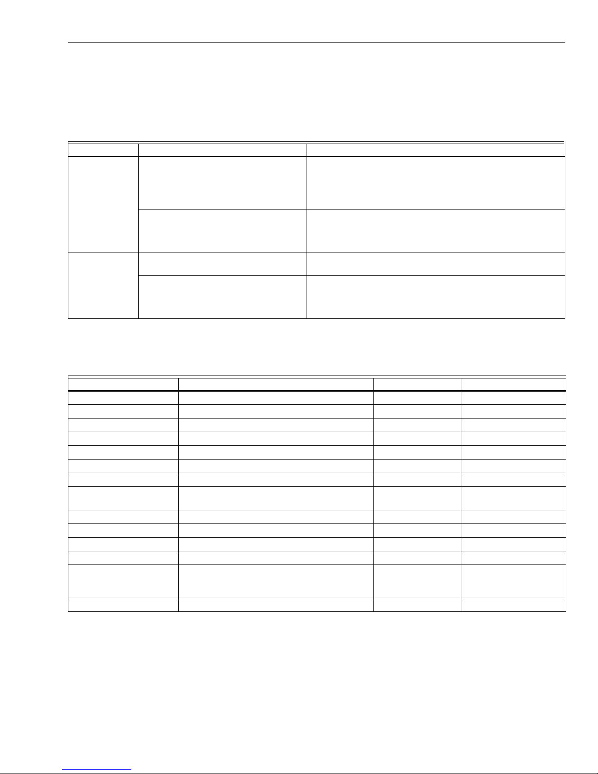
Table 5. Recommended Humidistat Settings.
OPERATION
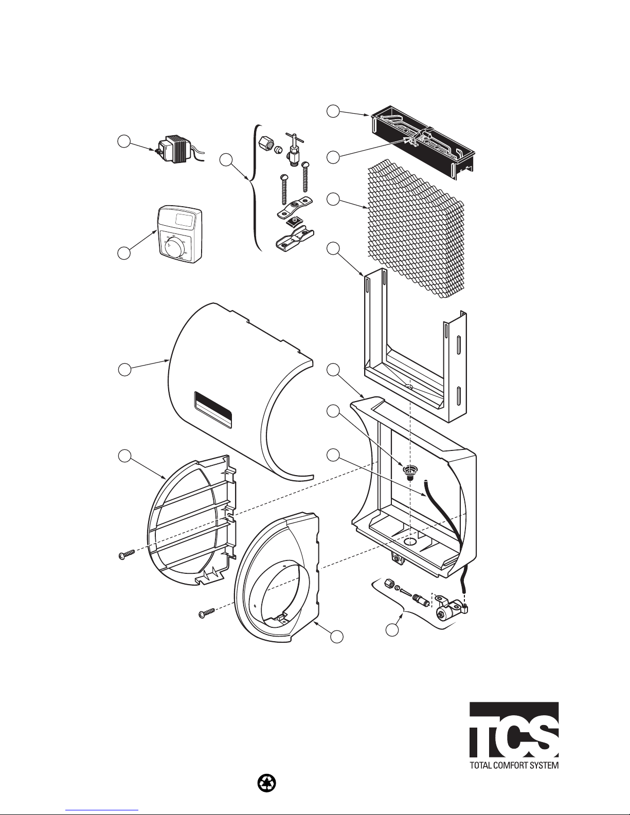
The HE220A and HE260A Humidifiers use the principle that
vapor (evaporated water) is created when warm air blows
over a water soaked area. As the vapor circulates, the relative
humidity rises.
The humidity control monitors the relative humidity and
activates the humidifier accordingly. The humidifier has a
water supply that disburses water over a humidifier pad. The
Outside
Temperature
Use This
Setting
Outside
Temperatuer
Use This
Setting
-20°F (-29°C) 15 +10°F (-12°C) 30
-10°F (-23°C) 20 +20°F (-7°C) 35
-0°F (-18°C) 25 +Above 20°F
(Above -7°C)
40
Humidity Control
Régulateur d'humidité
-20 °F
-10 °F
0 °F
+10 °F
+20 °F
Over 20 °F
15%
20%
25%
30%
35%
40%
HUMIDITY
SETTING
OUTDOOR
TEMPERATURE
-30 °C
-25 °C
-20 °C
-10 °C
-5 °C
Over 0 °C
M2084
0
CASE REMOVA
L
SLOT
HOLE FOR WIRING
THE DUCT MOUNTING
INSTALLATIONS
H8908B

HE220A AND HE260A BYPASS FLOW-THROUGH HUMIDIFIER
68-0272 6
warm dry air from the furnace passes over the humidifier pad
and collects moisture and them circulates it through the
house.
Humidified air feels warmer and more comfortable so the
homeowner may be able to lower the thermostat heating
setpoint and save money on heating fuel bills. The end result
is that the humidifier gives the homeowner a comfortable
environment that is also energy efficient.
MAINTENANCE
A regular maintenance program prolongs the life of the
humidifier and provides a more comfortable environment.
Either hard or soft water can be used in the humidifier.
Frequency of cleaning depends on the condition of the water.
CAUTION
Voltage Hazard.
Can cause electrical shock and equipment
damage.
Disconnect power supply before installing or servicing.
IMPORTANT
Never oil any part of the humidifier.
Every 1 to 3 Months (Depending on Water
Quality)
Use the following procedure to clean the humidifier:
1. Disconnect the power and turn off the humidifier water
supply.
2. Remove the humidifier cover. See Fig. 5.
3. Remove the humidifier pad assembly from the humidi-
fier by grasping the tray and pulling it toward you.
4. Pull one side of the humidifier pad assembly frame
toward you and remove the tray from the frame.
5. Gently pinch the water nozzle catches inward until the
water nozzle can be lifted off the tray.
6. Slide the humidifier pad out of the frame.
7. Carefully scrape any mineral deposits from the tray and
frame. Be sure the frame drain hole has nothing block-
ing it.
8. Check the humidifier pad and if excessive mineral
deposits are present, replace with a new pad.
9. Disconnect the tube from the drain fitting on the bottom
of the humidifier housing.
10. Clean the drain fitting, if necessary.
11. Bend the drain tube to loosen any mineral deposits.
12. Flush the drain tube with pressurized water (a running
tap) to clean the tube.
13. Reattach the drain tube to the drain fitting.
14. Slide the humidifier pad back into the frame.
IMPORTANT
Be sure the marked side of the humidifier pad is fac-
ing up for proper performance.
15. Snap the water nozzle back on the tray.
16. Reattach the tray to the frame.
17. Place humidifier pad assembly in humidifier housing
and press until assembly is completely seated. Be care-
ful not to pinch or kink water feed tube.
18. Replace humidifier cover.
19. Verify humidifier operation by following steps in Check-
out Procedure section.
.
Fig. 5. Location of humidifier parts.
End of Humidification Season
At end of heating season, follow steps 1 through 18 from the
Every 1 To 3 Months section to clean humidifier and shut if off.
IMPORTANT
Be sure the humidifier power is off.
Beginning of Humidification Season
Refer to the Checkout Procedure section to complete the
humidifier startup.
Vacation
When leaving on vacation, turn off humidifier water supply and
humidity control. When returning from vacation, turn on
humidifier water supply and reset humidity control to restart
humidifier.
CHECKOUT PROCEDURE
After winter startup or servicing, use the following procedure
to check the humidifier operation:
1. Turn on the humidifier power and water supply.
2. Turn humidistat to the highest setting and set the
thermostat to 10°F (6°C) above room temperature.
3. Observe that water is flowing out of drain hose.
M20821
WATER
FEED NOZZLE
FRAME
HUMIDIFIER
HOUSING
WATER
FEED TUBE
HUMIDIFIER
PAD ASSEMBLY
COVER
SIDEWALL
BY-PASS SIDEWALL

HE220A AND HE260A BYPASS FLOW-THROUGH HUMIDIFIER
7 68-0272
NOTE: The furnace blower must be on for the humidifier to
operate.
4. Reset the thermostat and humidistat to a comfortable
setting for automatic operation.
TROUBLESHOOTING (TABLE 6)
Table 6. Troubleshooting Procedures.
REPLACEMENT PARTS (FIG. 6 AND TABLE 7)
Table 7. HE220A, HE260A Humidifier Replacement Parts..
Problem What To Look For What To Do
Low humidity Furnace blower not operating •Reset circuit breaker or check for blown fuse.
•Check that the furnace power is on.
•Check all external wiring connections.
•Check the humidity control setting.
•Call a professional heating contractor.
Rapid air changes. Drafts (cold air is dry
and is an added load to the humidifier
•Keep doors and windows closed.
•Close fireplace damper when not in use.
•Keep exhaust fan running time to a minimum.
•Seal around doors and windows.
High Humidity Condensation on walls •Turn humidity control and water off until condensation is
completely evaporated.
Heavy condensation on windows. •Turn humidity control down low enough to eliminate
condensation condensation caused by moisture from bathing,
mopping, cooking, etc. If moisture persists, move ventilation is
needed.
Exploded View Number Description HE220 Part Number HE260 Part Number
1 Side wall 32001612-001 32001626-001
2 Bypass side wall 32001613-001 32001627-001
3 Cover Assembly 32001611-001 32001611-002
4 PerfectFlo™ water distribution tray 32001619-001 32001630-001
5 Humidifier pad HC22A1007 HC26A1008
6 Frame 32001621-001 32001632-001
7 Drain fitting 32001615-001 32001615-001
8 Solenoid valve assembly (includes water feed
tube and nozzle)
32001639-002 32001639-002
9 Saddle valve assembly 32001616-001 32001616-001
10 Transformer (10 VA) 32001652-001 32001652-001
11 Humidistat H8908B1069 H8908B1069
12 Base insert assembly, includes no. 8 above 32001625-001 32001625-002
— Hardware Kit for Solenoid Assembly (same as
Solenoid valve assembly without the solenoid
valve)
32001752-001 32001752-001
— Current Sensing Relay 32001754-001 32001754-001

68-0272 G.H. 10-02 www.honeywell.com/yourhome
Automation and Control Solutions
Honeywell Honeywell Limited-Honeywell Limitée
1985 Douglas Drive North 35 Dynamic Drive
Golden Valley, MN 55422 Scarboroug, Ontario
MiV 4V9
Printed in U.S.A. on recycled
paper containing at least 10%
post-consumer paper fibers.
HE220A AND HE260A BYPASS FLOW-THROUGH HUMIDIFIER
Fig. 6. Exploded view of humidifier parts.
M20845
9
10
11
3
6
7
5
4
8
1
2
12
8
8
Humidity Control
Régulateur d'humidité
Other manuals for HE220A
1
This manual suits for next models
1
Table of contents
Other TCS Humidifier manuals