TCS HE360A Operation manual

PRODUCT DATA
68-0273
® U.S. Registered Trademark
Copyright © 2002 • All Rights Reserved
HE360A
Powered Flow-Through Humidifier
APPLICATION
The HE360A Powered Flow-Through Humidifiers work with
the warm air furnace blower to provide humidification for the
whole house.
FEATURES
• Capable of humidifying the largest areaup to
4200 sq ft (390 sq m)of any flow-through humidifier.
• Includes the PerfectFlo™ water distribution tray for
optimal efficiency and water usage.
• Proven technology used for high performance
humidification.
• Narrower footprint than popular compatible model
while maintaining a common humidifier pad and
comparable humidification performance.
• Interior components designed for quick maintenance
and service.
• Continuous flushing reduces the maintenance
frequency.
Contents
Application ........................................................................ 1
Features ........................................................................... 1
Specifications ................................................................... 2
Ordering Information ........................................................ 2
Installation ........................................................................ 3
Wiring Humidifier .............................................................. 4
Checking Installation ........................................................ 5
Operating Humidifier ........................................................ 5
Operation .......................................................................... 5
Maintenance ..................................................................... 5
Checkout Procedure ......................................................... 6
Troubleshooting ................................................................ 7
Replacement Parts ........................................................... 7

HE360A POWERED FLOW-THROUGH HUMIDIFIER
68-0273 2
ORDERING INFORMATION
When purchasing replacement and modernization products from your Total Comfort System wholesaler or distributor, refer to the
Total Comfort System catalog or price sheets for complete ordering number.
If you have additional questions, need further information, or would like to comment on our products or services, please write or
phone:
Unitary Product Group Consumer Relations
5005 York Drive
Norman, OK 73069
Phone: (877) 874-7378
SPECIFICATIONS
IMPORTANT
Specifications given in this publication do not include
normal manufacturing tolerances. Therefore, this unit
may not exactly match the listed specifications. Also,
this product is tested and calibrated under closely
controlled conditions and some minor differences in
performance can be expected if those conditions are
changed.
Total Comfort System Model Available:
HE360A: Includes humidifier, humidifier pad, mounting
template, self-piercing saddle valve and H908 Convertible
Humidity Control.
Capacity: At 120°F (49°C) plenum temperature and
0.20 static pressure drop across supply and return:
18 gallons per day (gpd), 68 liters per day (lpd).
Humidified Area:
Electrical Ratings: 120 Vac, 60 Hz, 0.7A.
Humidifier Pad Dimensions (height x width x depth):
13 in. x 10 in. x 1-1/2 in. (330 mm x 254 mm x 38 mm).
Plenum Opening Dimensions (height x width):
14-1/16 in. x 13-1/2 in. (357 mm x 343 mm).
Drain Connection: 1/2 in. (13 mm) I.D. plastic hose
connected directly to drain fitting on unit.
Dimensions: Refer to Fig. 1.
Fig. 1. HE360A dimensions in in. (mm).
Approvals:
Underwriters Laboratories Inc.: Listing Pending.
Canadian Underwriters laboratories Inc.: Listing Pending.
Standards: Air Conditioning and Refrigeration Institute
Tested: Standard 610.
House
Description
Air Changes
Per Hour
Area (Up To)
Sq ft Sq m
Loose Two 1,900 175
Average One 2,700 248
Tight One-half 4,200 386
M20810
15-1
/4
(387
)
14 (356)
10-1/4 (260)

HE360A POWERED FLOW-THROUGH HUMIDIFIER
3 68-0273
INSTALLATION
When Installing this Product...
1. Read these instructions carefully. Failure to follow them
could damage the product or cause a hazardous
condition.
2. Check ratings given in instructions and on the product to
ensure the product is suitable for your application.
3. Installer must be a trained, experienced service
technician.
4. After installation is complete, check out product
operation as provided in these instructions.
CAUTION
Personal Injury or Equipment Hazard.
Improper drilling can cause equipment damage or
personal injury.
Do not cut or drill into any air conditioning or electrical
accessory.
CAUTION
Property or Equipment Hazard.
Can cause property or equipment damage.
• Locate the humidifier where the ambient
temperature is between 32°F (0°C) and 160°F
(71°C).
• Do not install where freezing temperatures could
occur.
• Be sure supply plenum static pressure is no greater
than 0.4 in. wc and water pressure is no greater
than 125 psi.
Location and Mounting
IMPORTANT
Mount the humidifier at least 3 in. (76 mm) above the
furnace jacket to allow adequate space for the drain
line. Check that there is adequate space above the
humidifier to remove and install the humidifier cover.
Do not install on a furnace jacket.
1. Determine the best location for the humidifier and draw
a level line on the plenum. See Fig. 2 and 3.
IMPORTANT
Be sure the template is level before marking to
assure optimal product performance.
2. Tape the template in position and trace around the tem-
plate.
3. Remove the template and carefully cut the rectangular
opening.
4. Loosen the thumbscrew on the bottom of the humidifier
and remove the cover.
5. Remove the humidifier pad assembly by grasping the
top of the tray and pulling the assembly out of the
housing. See Fig. 4.
6. Position the securing clips as shown in Fig. 5. Do not
completely seat them.
Fig. 2. Typical humidifier installation locations.
Fig. 3. HE360 Humidifier location in relation to air
conditioning cooling coils.
M12808A
HORIZONTAL
DOWN
FLO
LOWBOY
RETURN RETURN
R
ETURN
HIGHBOY
RETURN
M12812
A

HE360A POWERED FLOW-THROUGH HUMIDIFIER
68-0273 4
Fig. 4. Humidifier components.
Fig. 5. Position securing clips.
7. Position the humidifier housing in the hole (be sure it is
level), so the locking tabs are in place on the upper and
lower sheet metal edges of the hole.
8. Push in the securing clips until completely seated.
9. Drill holes and install the three sheet metal screws at
the top of the humidifier housing. Secure the housing
with the three remaining screws at the bottom of the
housing.
10. Reinstall the humidifier pad assembly in the humidifier
housing.
IMPORTANT
For proper operation, be sure the mark on the end of
the humidifier pad is facing up. Check that the water
feed tube is placed in the guide slots of the humidifier
housing.
11. Hook the top of the cover to the housing and secure
with the thumbscrew located at the bottom of the cover.
WIRING HUMIDIFIER
WARNING
Serious Personal Injury or Equipment Hazard.
Moving parts can cause electrical shock and
injury.
• Disconnect power supply before installation or
servicing.
• This device contains a moving fan blade; do not
operate the humidifier without the cover securely
attached.
IMPORTANT
All wiring must agree with applicable codes,
ordinances and regulations.
H8908 Humidistat Wiring Connections
IMPORTANT
• Select models of fan centers include humidifier taps
so the current sensing relay or sail switch is not
needed.
• If not using a current sensing relay or sail switch, the
120V humidifier plug must be energized during
blower motor cycles for proper operation.
1. Wire the current sensing relay or sail switch.
2. Connect only the two yellow wires to the humidity
control (red wire connections are not used for
mechanical humidity control).
NOTE: For additional mounting and wiring information, refer
to the humidity control installation instructions.
Plumbing Saddle Valve
Hot or cold water, either hard or softened, can be used in the
humidifier.
1. Use the self-piercing saddle valve included to tap into
the water supply line at an appropriate location.
CAUTION
Equipment Hazard.
Improper installation can cause equipment
damage.
Do not use any line connected to an air conditioner.
IMPORTANT
• The saddle valve is not designed to regulate water
flow; the valve is either open or closed.
• Be sure to install the saddle valve handle pointing
toward the ceiling to prevent debris from clogging the
solenoid in-line filter.
NOTE: Lightly clean the copper tubing ends with fine
sandpaper before making any connections.
M2081
1
COVER
ASSEMBLY
H
UMIDIFIER
P
AD ASSEMBLY
FEED TUBE NOZZLE
W
ATER
D
ISTRIBUTION TRAY
HUMIDIFIE
R
HOUSING
T
HUMB
S
CREW
M1281
3
CLIP CLIP

HE360A POWERED FLOW-THROUGH HUMIDIFIER
5 68-0273
2. Use 1/4 in. O.D. copper tubing and connect the saddle
valve to the inlet side of the solenoid valve.
a. Place the brass compression nut over the copper
tubing.
b. Slide the brass ferrule over the tubing.
NOTE: Do not over-tighten the compression nut.
Moderate tightness prevents leaking.
c. Insert tubing into the solenoid valve fitting. Support
the valve while tightening the compression nut.
3. Connect a 1/2 in. hose to the humidifier drain fitting and
run it to a suitable drain.
NOTE: Slope the hose downward for correct drainage.
CHECKING INSTALLATION
1. Open the saddle valve.
NOTE: The furnace blower must be operating for the
humidifier to work.
2. Set the thermostat setpoint 10°F (12°C) above the room
temperature.
3. Set the humidity control to a high humidity setting, or
place the humidity control in the test position.
4. Observe the water running out of the drain line to be
sure the humidifier is working correctly.
5. Check for leaks.
6. Reset the thermostat and humidity control to
comfortable settings.
OPERATING HUMIDIFIER
The Total Comfort System HE360A Humidifier is controlled by
the H8908 Humidistat. The humidistat is installed either on an
interior wall in the living area, or on the return air duct. Choose
the humidity control setting using the combination relative
humidity/outdoor temperature setting scale on the humidity
control dial. Match the dial setting to the outdoor temperature
for optimizing the humidity level to reduce the moisture
condensation on your windows. Table 1 can also be used to
adjust the humidity control to the recommended setting.
NOTE: As outside temperature drops, the recommended
humidity control setting is lowered to accommodate
the effects of dewpoint. These settings should
reduce the accumulation of moisture and ice on the
windows and in other areas of the house.
Some indoor activities such as cooking, showering and
clothes drying can cause excessive levels of humidity and
start the accumulation of moisture on the windows. If this
condition persists for more than a few hours, set the
humidistat to the lowest setting to turn off the humidifier. If the
condition does not improve, ventilate the house to remove the
moisture.
OPERATION
The HE360A Humidifiers use the principle that vapor
(evaporated water) is created when warm dry air blows over a
water-soaked area. As the vapor circulates, the relative
humidity rises.
The humidity control monitors the relative humidity and
activates the humidifier accordingly. The humidifier has a
water supply that disburses water over a humidifier pad. The
warm dry air from the furnace passes over the humidifier pad,
collects moisture, and circulates it through the house.
Since humidified air feels warmer and more comfortable, the
homeowner may decide to lower the thermostat setpoint, thus
saving money on heating bills. The end result is that the
humidifier provides a more comfortable environment that is
also energy efficient.
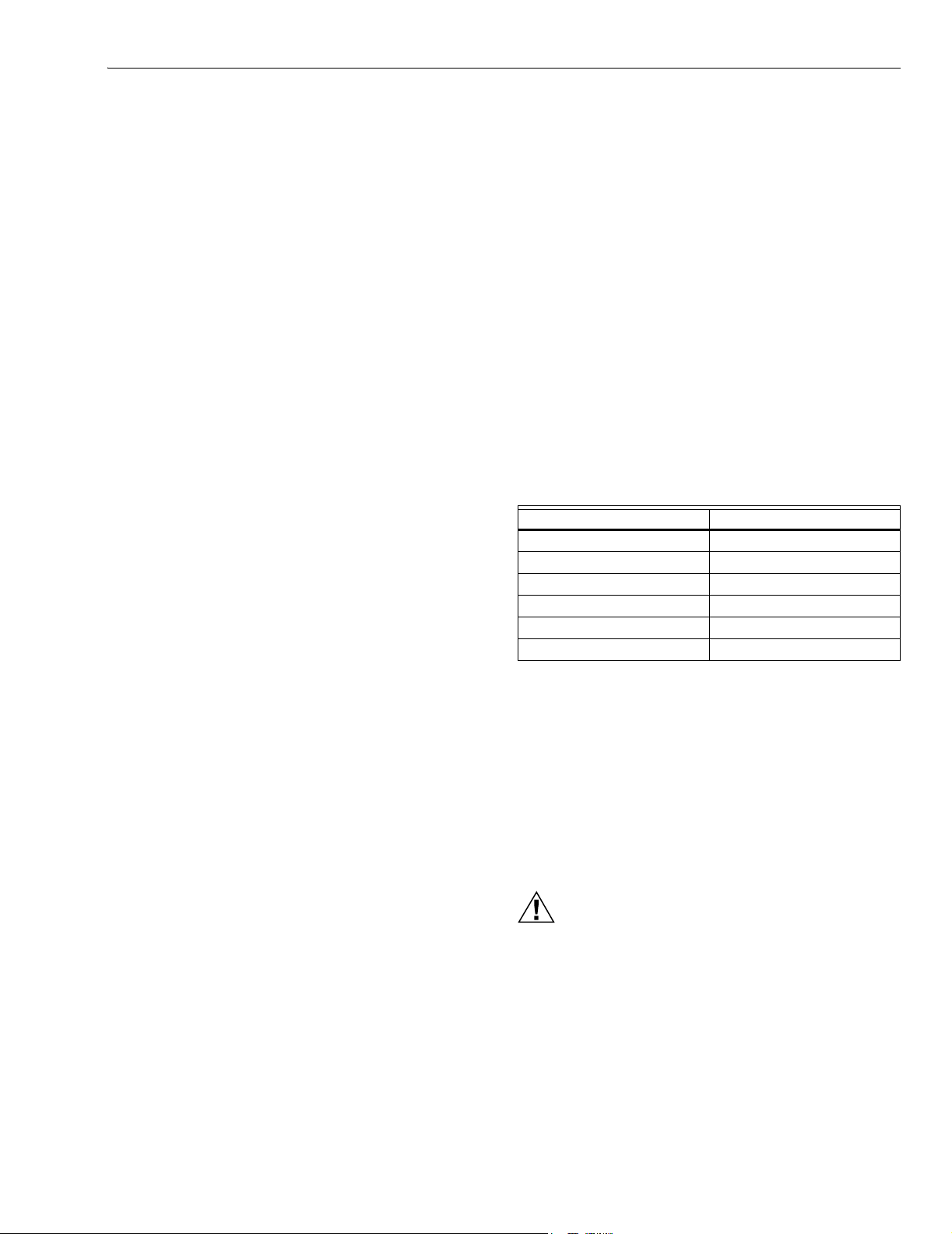
Table 1. Recommended Humidity Control Settings.
MAINTENANCE
A regular maintenance program prolongs the life of the
humidifier and provides a more comfortable environment.
Cleaning frequency depends on water conditions.
Either hard or soft water can be used in the humidifier, but
hard water mineral deposits are more difficult to clean then
soft water deposits.
Use the following procedure to clean the humidifier.
CAUTION
Personal Injury or Equipment Hazard.
Power Supply can cause electrical shock or
equipment damage.
Disconnect power supply before performing humidifier
maintenance.
IMPORTANT
Never oil any part of the humidifier.
Outside Temperature Recommended Setting
-20°F (-29°C) 15
-10°F (-23°C) 20
0°F (-18°C) 25
+10°F (-12°C) 30
+20°F (-7°C) 35
Above +20°F (-7°C) 40

HE360A POWERED FLOW-THROUGH HUMIDIFIER
68-0273 6
Every 1 To 3 Months
(Depending on Water Quality)
1. Disconnect the power and turn off the humidifier water
supply.
2. Remove the humidifier cover. See Fig. 6.
Fig. 6. Location of humidifier parts.
3. Remove humidifier pad assembly from the humidifier by
grasping the tray and pulling it toward you.
4. Pull one side of the humidifier pad assembly frame
toward you and remove the tray from the frame.
5. Gently pinch the water nozzle catches inward until the
water nozzle can be lifted off the tray.
6. Slide the humidifier pad out of the frame.
7. Carefully scrape any mineral deposits from the tray and
frame. Be sure the frame drain hole has no blockage.
8. Check the humidifier pad and if excessive mineral
deposits are present, replace with a new pad.
9. Disconnect the drain hose from the drain fitting on the
bottom of the humidifier housing.
10. Clean the drain fitting, if necessary.
11. Bend the drain hose to loosen any mineral deposits.
12. Flush the drain hose with pressurized water (a running
tap) to clean the hose.
13. Reattach the drain hose to the drain fitting.
14. Slide the humidifier pad back into the frame.
IMPORTANT
For proper performance, ensure the marked end of
the humidifier pad is upward facing.
15. Reattach the tray to the frame.
16. Snap the water nozzle back on the tray.
17. Place the humidifier pad assembly in the humidifier
housing and press until the assembly is seated.
18. Be sure the water feed tube is placed in the guide slots
of the humidifier housing.
19. Replace the humidifier cover.
20. Verify the humidifier operation by following the steps in
the Checkout Procedure section.
End of Humidification Season
The humidifier needs to be cleaned and shut off at the end of
the heating season. Follow steps 1 through 19 from the Every
1 To 3 Months section.
IMPORTANT
Be sure the humidifier power is off.
Beginning of Humidification Season
Refer to the Checkout Procedure section for complete
humidifier startup instructions.
Vacation
Turn off the humidifier water supply and the humidity control
while on vacation. When you return, turn on the humidifier
water supply and reset the humidity control to restart the
humidifier.
CHECKOUT PROCEDURE
After winter startup or servicing, use the following steps to
check the humidifier operation.
1. Turn on the humidifier power and water supply.
2. Turn humidity control to its highest setting and set the
thermostat to 10°F (12°C) above the room temperature.
3. Observe that water is flowing out of the drain hose.
NOTE: The furnace blower must be operating for the
humidifier to work.
4. Reset thermostat and humidity control to a comfortable
setting for automatic operation.
M2081
1
COVER
ASSEMBLY
H
UMIDIFIER
P
AD ASSEMBLY
FEED TUBE NOZZLE
W
ATER
D
ISTRIBUTION TRAY
HUMIDIFIE
R
HOUSING
T
HUMB
S
CREW

HE360A POWERED FLOW-THROUGH HUMIDIFIER
7 68-0273
TROUBLESHOOTING
Refer to Table 2 for troubleshooting procedures.
Table 2. Troubleshooting Procedures.
REPLACEMENT PARTS
Refer to Fig. 7 and Table 3 when ordering replacement parts.
Table 3. List of Replacement Parts for HE360.
Problem What To Look For What To Do
Low
humidity
Furnace blower not
operating.
•Reset circuit breaker or check for blown fuse.
•Check that the furnace power is on.
•Check all external wiring connections.
•Check the humidity control setting.
•Call a professional heating contractor.
Rapid air changes.
Drafts (cold air is dry
and is an added load to
the humidifier).
•Keep doors and windows closed.
•Close fireplace damper when not in use.
•Keep exhaust fan running time to a minimum.
•Seal around doors and windows.
High
humidity
Condensation on walls. •Turn off humidity control and water until condensation is completely evaporated.
Heavy condensation
on windows.
•Turn down humidity control low enough to eliminate condensation caused by moisture
from bathing, mopping, cooking, etc. If moisture persists, more ventilation is needed.
Description Part Number
1 Feed Tube Nozzle 32000408-001
2 Water Distribution Tray 32001630-001
3 Solenoid Valve Assembly (Includes water feed tube) 32001876-001
4 Humidifier Pad HC26A1008
5 PWB Assembly 32001676-001
6 Frame 32001632-001
7 Base/Insert Assembly 32001660-001
8 Fan Blade 32000429-001
9 Motor Mount 32001670-001
10 Fan Shroud 32001664-001
11 Fan Motor 32000416-001
12 Bag Assembly, Saddle Valve 32001616-001
13 Humidistat H8908B1069
14 Relay 32001754-001
15 Cover/Screw Assembly 32001663-001
16 Power Cord 32000423-001
17 Drain Fitting 32001615-001
Not shown Hardware Kit for Solenoid Assembly
(same as Solenoid Valve Assembly without the solenoid valve)
32001752-001

68-0273 G.H. 10-02 www.honeywell.com/yourhome
Automation and Control Solutions
Honeywell Honeywell Limited-Honeywell Limitée
1985 Douglas Drive North 35 Dynamic Drive
Golden Valley, MN 55422 Scarboroug, Ontario
MiV 4V9
Printed in U.S.A. on recycled
paper containing at least 10%
post-consumer paper fibers.
HE360A POWERED FLOW-THROUGH HUMIDIFIER
Fig. 7. Exploded view of humidifier parts.
1
7
2
16
M20812A
3
1
1THE HE360A INCLUDES THE H8908B HUMIDISTAT.
15
9
12
4
6
10
13
14
18
8
5
11
Humidity Control
Régulateur d'humidité
Table of contents
Other TCS Humidifier manuals