TCT Mobile B10C/OT-565 Technical manual

B10C/OT-565(A) Repair Document
ED 1.0 B10C Level 2 Repair Document
1/26
All right reserved. Passing on and copying of this document, use and communication are not permitted
without authorization
Repair Document
B10C/OT-565
Note: this manual is non-contractual and TCT Mobile phone can modify without prior notice the
characteristics of described equipments.
B10C/OT-565(A) Repair Document
ED 1.0 B10C Level 2 Repair Document
2/26
All right reserved. Passing on and copying of this document, use and communication are not permitted
without authorization
HISTORY
Date Version Author Comments
2010-6-25 0.5 Rao Lihong The first create
2010-07-07 1.0 Frank Tu Release
Function Name Date Signature
Written by CPM Frank
Verified by
Approved by
B10C/OT-565(A) Repair Document
ED 1.0 B10C Level 2 Repair Document
3/26
All right reserved. Passing on and copying of this document, use and communication are not permitted
without authorization
CONTENT
1. LEVEL 2 REPAIR PROCESS ......................................................................................4
2. VISUAL INSPECTION AND WARRANTY CHECK....................................................5
2.1 Warranty Check.........................................................................................................5
2.2 Pretest.......................................................................................................................5
3. CLONING TOOL.........................................................................................................8
4. SAV TEST TOOL (STT)...............................................................................................8
5. SOFTWARE UPGRADING..........................................................................................8
6. LOCAL DOWNLOADING...........................................................................................9
7.
DISASSEMBLY and REASSEMBLY of OT-565
..........................................................11
7.1 ESD Safety..............................................................................................................11
7.2 Disassembly tools ....................................................................................................11
7.3 Process....................................................................................................................11
7.4 Reassembly Process .................................................................................................16
7.5 Disassembly process evaluation.................................................................................17
7.6 Disassembly Complete .............................................................................................19
8. LEVEL 2 REPAIR......................................................................................................20
9. BOARD EXCHANGE.................................................................................................20
10. OTHER COMPONENT EXCHANGE.......................................................................20
11. STICKERS ...............................................................................................................21
12. FINAL TEST ............................................................................................................22
12.1 Function Test.........................................................................................................22
12.2 Measurement .........................................................................................................22
APPENDIX 1 Tools and Equipments for L2 Repair Center.............................................25
APPENDIX 2 Packaging Requirements...........................................................................26
B10C/OT-565(A) Repair Document
ED 1.0 B10C Level 2 Repair Document
4/26
All right reserved. Passing on and copying of this document, use and communication are not permitted
without authorization
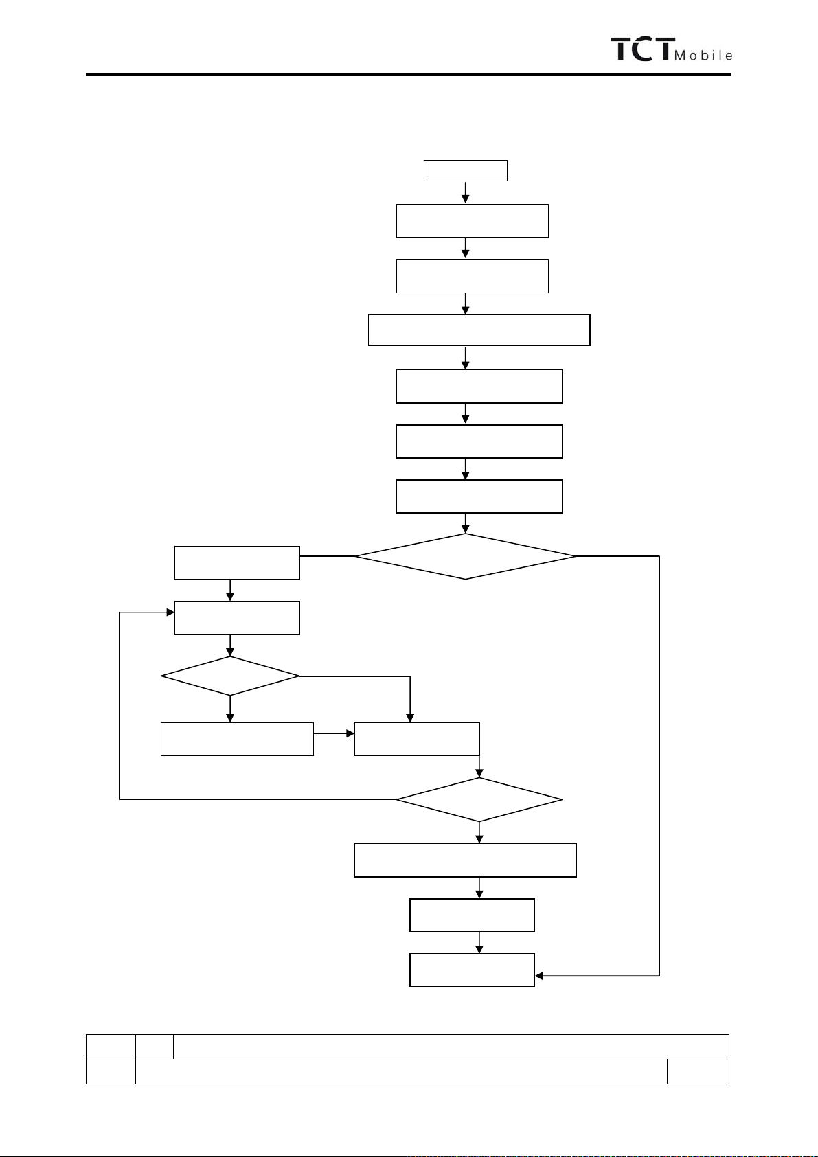
1. LEVEL 2 REPAIR PROCESS
R
ecord
in BIG
Function Test
Restore the user information
SW Upgrading
Data
Cloning
STT
Visual inspection
Start
Pretest & Faulty confirmation
NG
Disassembly
NG
L2 repair
Reassembly
Board replacing
Retest Ok
NG
Retest
The End
Warranty check
Ok
OK
B10C/OT-565(A) Repair Document
ED 1.0 B10C Level 2 Repair Document
5/26
All right reserved. Passing on and copying of this document, use and communication are not permitted
without authorization
2. VISUAL INSPECTION AND WARRANTY CHECK
2.1 Warranty Check
Warranty confirmation of L1:
¾IMEI sticker check:
1) The IMEI number MUST be the same with the one on the IMEI sticker. If not, it’s out of warranty
policy
2) IMEI label should NOT be removed/ scratch or unreadable/ not approved or provided by Alcatel.
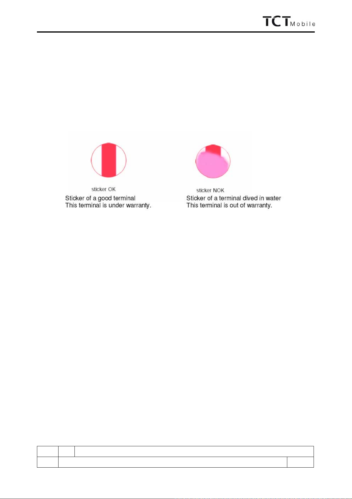
¾Humidity sticker: Liquid detection on humidity sticker
¾Visual mechanical check;
1) Corrosion: corrosion on the USB connectors, SIM connectors, and other metal surfaces
2) Holes (diam > 1mm): Holes on any surface, including the front casing, furnished frame, battery cover,
LCD Lens, keypad…
3) Big bumps (diam > 1mm): Bumps on any surface, including the front casing, furnished frame, battery
cover, LCD Lens, keypad…
4) Long scratch (length > 3mm): Scratches on any surface, including the front casing, furnished frame,
battery cover, LCD Lens, keypad…
5) Distortion: Bend, twisted or crushed on the h/s, cover/casing or connectors…
6) Broken: LCD broken, casing/cover broken…
7) Fallen off: Keypad tear off, LCD lens, connectors fallen off …
8) Gap: External physical damage relating to abnormal use, like front case and frame opened
9) Others:
-Damage caused by disassembly like wrong part assembly, lost of components
-Use in abnormal environment like too high temperature with plastic melts
2.2 Pretest
¾Power on the cell phone.
¾Insert a battery, plug a charger on product, and check the icon on main display or sub display.
¾If the cell phone asks to input NCK code, which means it’s SIM locked, and can only be worked with
dedicated SIM card. Use the correct SIM card.
¾Enter the super code to unlock the phone if necessary.
¾If power on OK, test step by step with the auto test code. Press *#2886# on the idle screen to start auto test.

B10C/OT-565(A) Repair Document
ED 1.0 B10C Level 2 Repair Document
6/26
All right reserved. Passing on and copying of this document, use and communication are not permitted
without authorization
a) Check Traceability Information:
Screen display the traceability information. If they are all right, press Pass to continue.
b) LCD display test:
The patterns are displayed on the main screen from "COLOR" pattern, "BLACK" pattern,
"CHECKER" pattern, "GREY CHART" pattern, "WHITE" pattern, "MENU" pattern, "MacBeth"
pattern. If they are all right, press Pass to continue.
c) Sub-LCD display test:
Display “Hello my friend!” in the sub-LCD.
Display confirm information in main LCD.
If they are all right, press Pass to continue.
d) Main LCD backlight test:
The backlight will be auto on and off, if it works all right, press Pass to continue.
e) Keypad backlight test:
Keypad backlights begin flashing, if it works all right, press Pass to continue.
f) Keypad test:
The operator presses all keys. If all keys are pressed, go to next text item automatically. Timeout is
fixed to 40s.
g) Vibrator test:
Vibrator begins to work, if it works all right, press Pass to continue.
h) Camera Test:
Display the Camera Screen then go to result confirm screen. If it works all right, press Pass to
continue.
i) Camera Zoom Test:
Display Camera zoom screen first. If it works all right, press Pass to continue.
j) SIM card test:
Display “testing…” during the wait of the status.
Display “Insert SD card” if no SD card inserted
Timeout is fixed to 15s.
If pass, screen display “OK” for 1s and go to the next test item automatically.
k) USB charger test:
Display “testing…” during the wait of the status.
Display “Insert USB charger” if no USB charger inserted
Timeout is fixed to 15s.
If pass, screen display “OK” for 1s and go to the next test item automatically.
l) SD card test:
Display “testing…” during the wait of the status.
Display “Insert SD card” if no SD card inserted
Timeout is fixed to 15s.
If pass, screen display “OK” for 1s and go to the next test item automatically.
m) Bluetooth test:
Display “searching…” during the wait of the status.
Timeout is fixed to 20s.
If pass, screen display “OK”(include BT device info and address ) for 1s and go to the next test item
automatically.
n) Audio connector test:
Display “testing…” during the wait of the status.
Display “Insert audio connector”, if no audio connector inserted.
Timeout is fixed to 15s.
If pass, screen display “OK” for 1s and go to the next test item automatically.
o) Headset left test:
The operator does a small acoustic test, he speaks in the headset microphone and estimates the audio
quality when he ears the signal in headset left earphone. If it works all right, press Pass to continue.
p) Headset right test:
The operator does a small acoustic test, he speaks in the headset microphone and estimates the audio
quality when he ears the signal in headset right earphone. If it works all right, press Pass to continue.
q) Headset test:
The operator does a small acoustic test, he speaks in the headset microphone and estimates the audio
quality when he ears the signal in headset earphone. If it works all right, press Pass to continue.
r) FM play test:

B10C/OT-565(A) Repair Document
ED 1.0 B10C Level 2 Repair Document
7/26
All right reserved. Passing on and copying of this document, use and communication are not permitted
without authorization
The default frequency is 103.6MHz (1036)
Press "Enter" key to listen the radio.
The input frequency number should be 4 digits.
Delete the digit by pressing "LEFT" key.
The range of frequency is from 0875 to 1080.
Set next frequency by pressing "DOWN" key.
If it works all right, press Pass to continue.
s) Headset unplug test:
Display “Remove headset”, if any audio connector connected.
Timeout is fixed to 20s.
If pass, mini display “OK” for 1s and go to the next test item automatically.
t) Melody Test:
Play music with loud speaker. If it works all right, press Pass to continue.
u) Hall Test:
Screen display “Pls. Close Slide” and try to detect whether the slide is closed. Then, handset detector
whether the slide is opened by operator.
If pass, go to the next test item automatically.
Total timeout is fixed to 10s for waiting.
v) Temperature test:
Screen display the handset temperature. If it is regular, press Pass to continue.
w) Test status memorization
Screen display the test status.
¾Make a call.
¾Receive a call.
¾Reproduce the fault which end user complaint.

B10C/OT-565(A) Repair Document
ED 1.0 B10C Level 2 Repair Document
8/26
All right reserved. Passing on and copying of this document, use and communication are not permitted
without authorization
3. CLONING TOOL (TO be updated)
1) Find cloning tool on MLDC as below detail location:
2) Install the cloning tool in your computer.
3) Follow the user manual on MLDC to upgrade the mobile.
4. SAV TEST TOOL (STT)
1) Find STT on MLDC as below detail location:
2) Install the cloning tool in your computer.
3) Follow the user manual on MLDC to upgrade the mobile.
5. SOFTWARE UPGRADING
SW Upgrade tool is a method to download the SW from the SW upgrade server. Your internet connection is
necessary during the process.
1) Find software Upgrade tool on MLDC as below detail location:
2) Install the cloning tool in your computer.
3) Follow the user manual on MLDC to upgrade the mobile.

B10C/OT-565(A) Repair Document
ED 1.0 B10C Level 2 Repair Document
9/26
All right reserved. Passing on and copying of this document, use and communication are not permitted
without authorization
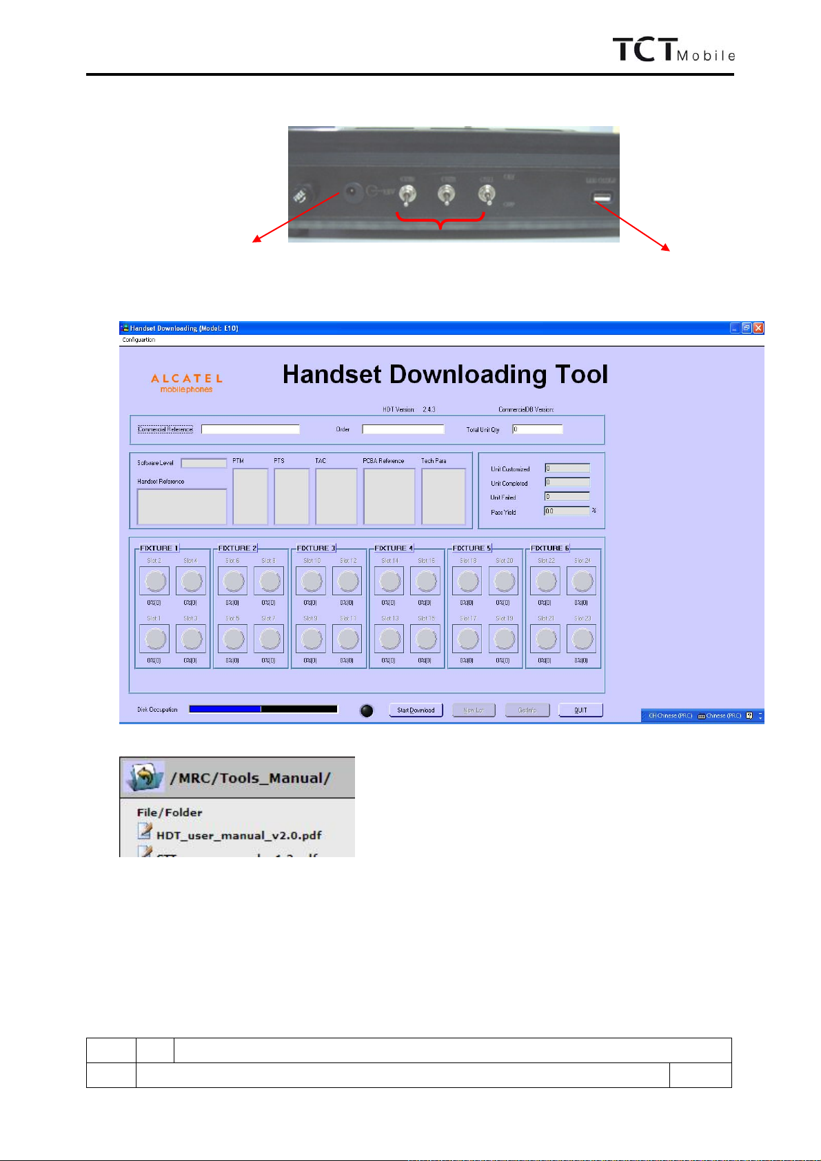
6. LOCAL DOWNLOADING
HDT is a tool for local software
downloading in RSH. There is no need of internet connection in the downloading
progress.
¾
Notice
: from OT-565 product, common MTK bench is used on HDT. This bench supports 3 channels
downloading in one time. The bench does not have a dongle inside, so insert the dongle into your computer
before downloading.
There are 2 kinds of sockets which can match the bench: handset socket for handset downloading, and PCBA socket
for PCBA downloading.
Steps:
1) Download HDT application for Easy from MLDC;
2) Download the SW (main code+perso+latest commercial DB) and install it under the default route;
3) Put the socket on the bench, and make sure they well connected to each other;
Put OT-565 PCBA onto the socket; also make sure they connected well;
+12V switch +12V light, red
+3.8V light, green
+3.8V switch
B10C/OT-565(A) Repair Document
ED 1.0 B10C Level 2 Repair Document
10/26
All right reserved. Passing on and copying of this document, use and communication are not permitted
without authorization
4) Power supply to the 12V connector; and connect to the computer with USB cable; Turn on the +12V switch,
and +12V light turn red;
5) Create the folder “B10C” under C:\HDTE10\IMEI\Delivery, and put IMEI file on it;
6) Start HDT application by double click “HDT.exe” in the folder of C:/HDTE10/Bin;
7) Detail steps on the user manual which you can find in:
Notice:
1) The bench supports 3-channel downloading, but when you press the red button, at most 2 in one time.
2) Change for handset socket when you need handset downloading; and the socket can be replaced by any other
module when you want to download other MTK product, without changing the bench.
To power supply To computer
Channel switch

B10C/OT-565(A) Repair Document
ED 1.0 B10C Level 2 Repair Document
11/26
All right reserved. Passing on and copying of this document, use and communication are not permitted
without authorization
7.
DISASSEMBLY and REASSEMBLY of OT-565
7.1 ESD Safety
Please wear static loop or static glove
7.2 Disassembly tools
You may use the following tools during the disassembly and reassembly procedure:
Plastic Wedge Screw driver Tweezers
Soldering iron Hot wind gun Soldering Jig
Hook Knife
Please make reference to APPENDIX 1 and find out the pictures of the tools.
7.3 Process
The steps of disassembly OT-565 are as below.
This module should only be disassembled from bottom to top.
Step 1:
Take off the battery cover, battery and SIM card if there is.
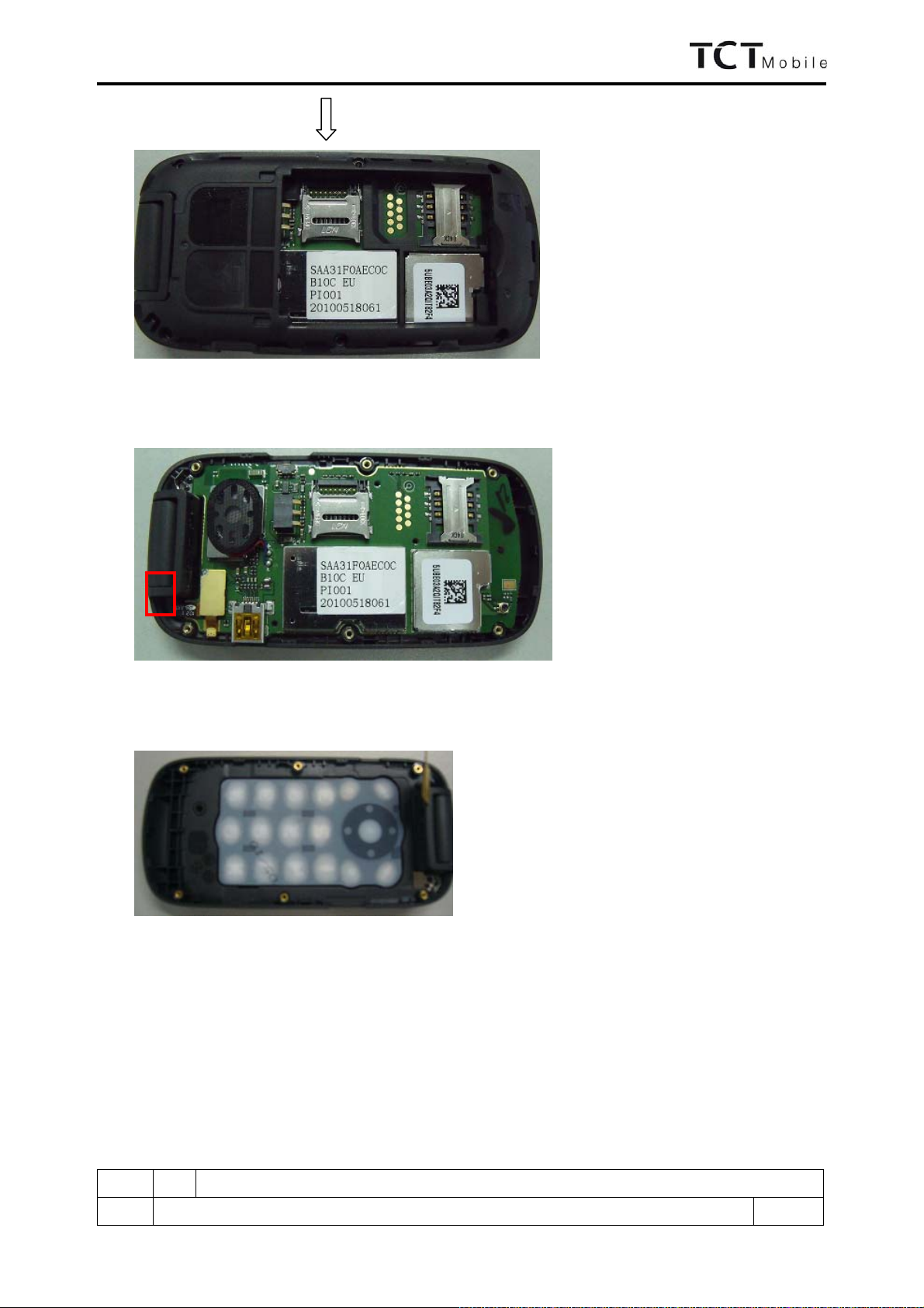
Step 2:
Take off the 6 screws from the furnished frame, take off the commercial label 7 from the battery house,
position as the below picture showed
1
6 4
5
3
2
7
B10C/OT-565(A) Repair Document
ED 1.0 B10C Level 2 Repair Document
12/26
All right reserved. Passing on and copying of this document, use and communication are not permitted
without authorization
Step3:
Separate the furnished frame and main PBCA.
Step 4:
Take off the main FPC connector 8, separate main PBCA from the furnished keypad casing
Step 5:
Remove keypad from keypad casing
8

B10C/OT-565(A) Repair Document
ED 1.0 B10C Level 2 Repair Document
13/26
All right reserved. Passing on and copying of this document, use and communication are not permitted
without authorization
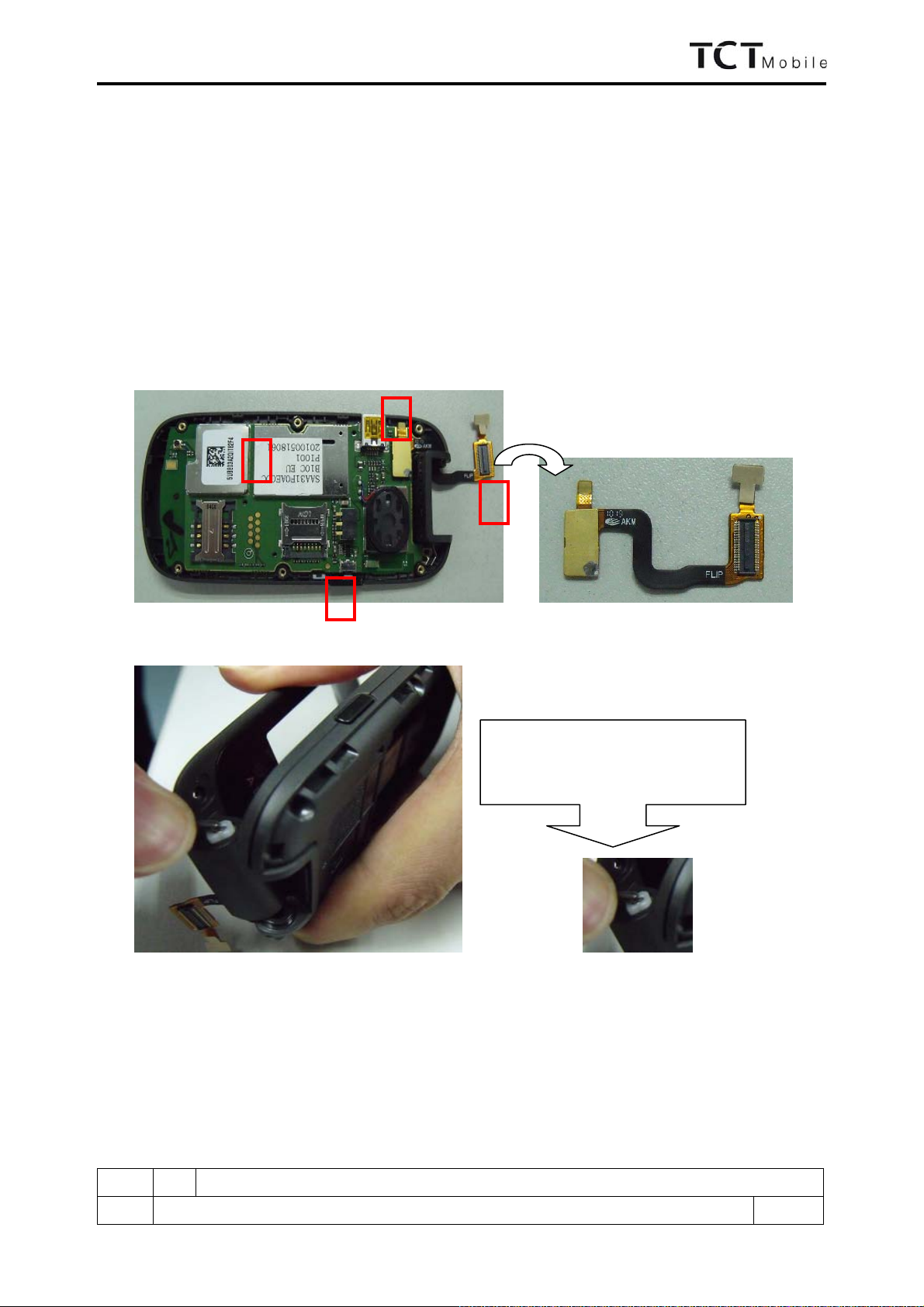
Step 6:
Remove left and right cap, take off the two screws below of them
Step 7:
Use knife to remove main LCD lens
Step 8:
Use Plastic Wedge to break the front case and back case then remove the back casing as below picture showed

B10C/OT-565(A) Repair Document
ED 1.0 B10C Level 2 Repair Document
14/26
All right reserved. Passing on and copying of this document, use and communication are not permitted
without authorization
Step 9:
Turn over the flip PBCA, remove the connector 9, and then take off the LCD module and camera module
Step 10:
Use Tweezers push the hinge stopper into the house, then separate the front casing and furnished keypad
casing
Step 11:
Use knife to take off the key film from main PBCA
9

B10C/OT-565(A) Repair Document
ED 1.0 B10C Level 2 Repair Document
15/26
All right reserved. Passing on and copying of this document, use and communication are not permitted
without authorization
Step 12:
Remove the following components from main PCBA with hot wind gun.
1-speaker 2-battery connector 3-SIM connector 4-RF connector 5-USB connector
6, 7, 8, 9, 10, 11, 12-LED
12-vibrator 13-receiver
Disassembly Notice:
1 32
5 4
6
7 8
10 9
11
13
12
B10C/OT-565(A) Repair Document
ED 1.0 B10C Level 2 Repair Document
16/26
All right reserved. Passing on and copying of this document, use and communication are not permitted
without authorization
Put all the spare parts on right position (don’t let all spare parts mixed and put on the clean place to
avoid vitiated or stained for each spare part) after disassembly. When taking apart of LCD and key film,
take care not to dirty or damage it.
7.4 Reassembly Process
Please make reference to the disassembly process for assembly reverse an order of the disassembly steps.
Attention:
1) Insert main FPC and assembly main PCBA with furnished keypad casing, lock the main FPC connector to
PCBA connector, and then place the side key, Assembly the furnished frame. Note the orientations of the
main FPC.
2) Assembly the front casing with furnished keypad casing
3) Assembly flip PBCA with the front casing, insert camera connector and main PFC connector to flip PBCA,
then assembly the back casing.
1
2
4
3
Push the hinge stopper into house,
then press front casing
B10C/OT-565(A) Repair Document
ED 1.0 B10C Level 2 Repair Document
17/26
All right reserved. Passing on and copying of this document, use and communication are not permitted
without authorization
4) Lock the four screws and place the LCD lens and the right and left caps.
7.5 Disassembly process evaluation
We list the OT-565 parts disassembly time, technique levels and disassembly methods as below, for technique
levels, Class 1 signifies easy to disassembly, Class 2 signifies normal to disassembly and Class 3 signifies hard
to disassembly.

B10C/OT-565(A) Repair Document
ED 1.0 B10C Level 2 Repair Document
18/26
All right reserved. Passing on and copying of this document, use and communication are not permitted
without authorization
spare part Time for
disassembly Jigs for
disassembly Difficulty
Class Remark
screw 3s screwdriver Class 1
Battery cover & side key 10s Plastic Wedge Class 1
Main PCBA & keypad 2s Class 1
Keypad casing with screws 20s screwdriver Class 1
Keypad sticker 5s Tweezers Class 1
Back casing 10s Plastic Wedge Class 2
Hinge with screws 20s Tweezers Class 1
Top keypad PCBA 1s Class 1
Main LCD module 3s Class 1
Main FPCA 5s Class 1
Receiver 3s Tweezers Class 1
LCD Conductive Foam 1s Tweezers Class 1
Top keypad 1s Tweezers Class 1
panel & front casing 10s Class 2
Main key film 10s Tweezers Class 1
Top key film 5s Tweezers Class 1
camera module Camera jig Class 2
vibrator 2s Soldering jig Class 1
speaker 2s Soldering jig Class 1
microphone 3s hot wind gun Class 2 easy to damage after
soldering for 2 or 3 times
LED 3s hot wind gun Class 2
camera socket 120s hot wind gun Class 3 easy to damage
USB connector 100s hot wind gun Class 2 easy to damage
B10C/OT-565(A) Repair Document
ED 1.0 B10C Level 2 Repair Document
19/26
All right reserved. Passing on and copying of this document, use and communication are not permitted
without authorization
battery connector 80s hot wind gun Class 3 Plastic parts are easily
damaged during heating
SIM connector 70s hot wind gun Class 3 Plastic parts are easily
damaged during heating
RF connector 15s hot wind gun Class 2
T-flash card connector 80s hot wind gun Class 3 Plastic parts are easily
damaged during heating
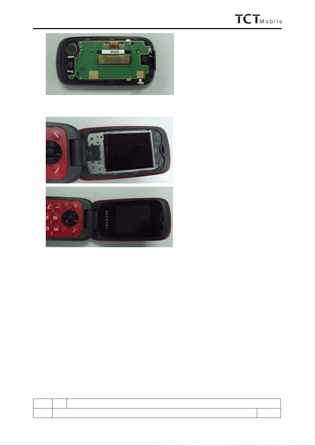
7.6 Disassembly Complete

B10C/OT-565(A) Repair Document
ED 1.0 B10C Level 2 Repair Document
20/26
All right reserved. Passing on and copying of this document, use and communication are not permitted
without authorization
8. LEVEL 2 REPAIR
This chapter describes the LEVEL 2 repairs that can be done without any diagnostic equipment.
Problem description Action And Solution
Charging Bad
or
No Charge
1.Check voltage of the battery: if 0V, charge some
minutes and check the charge indicator;
2.Check the battery contact, change the battery
connector if broken;
3.Check the charge plug on B cover, change it if
necessary;
Switch on with battery
power Can ‘t Switch on 1.Check voltage of the battery;
2.Check the battery contact, change the battery
connector if broken;
3.Check the keypad
4.Check BTB connector socket pin
Main display and Sub
display Missing line or column; no display;
bad or no LCD backlight Check Connection flex (FPC cable),change it if
necessary;
Replace display module if necessary;
Keyboard Keyboard backlight or keyboard
function Check keypad film or keypad PCB, change it if
necessary
Vibrator The vibrator does not work Check the contact on the PCBA (dirty or oxidized),
replace the vibrator if necessary;
Network Problem No emission or No reception Check the antenna contactor on the B cover;
Check the contact on the PCBA (dirty or oxidized);
TF card No communication between the
phone and the TF card Check the TF connector on the PCBA;
Camera Camera doesn't work Check camera module
Check also camera FPC broken or not
Audio Bad or no emission (TX audio from
mobile);
Bad or no reception (RX audio on
mobile);
Hands-free problem;
Key beep and melody problem
Check microphone, replace it if necessary;
Check the contact on the PCBA (dirty or oxidized)
Check loud speaker, replace it if necessary;
Check the contact on the PCBA (dirty or oxidized)
In case the LEVEL 2 repairs can’t solve the problem, or if the board is damaged, exchange the board.
9. BOARD EXCHANGE
In case that LEVEL 2 repair does not solve the failure, it is mandatory to change the board and apply the following
process:
1) Collect the fault PCBA board (without accessories LCD, vibrator, and camera), with microphone, and key
metal dome.
2) Get a new PCBA from swap stock. Reuse those accessories to assemble the mobile.
3) Fill in the fault sticker with IMEI number, the fault code, the short code, the Hardware Technical Level, and the
software version.
4) Send the fault PCBA with fault sticker back to L3 repair center with the suggested packaging method, the detail
packaging method please see solution 1 of APPENDIX 2.
10. OTHER COMPONENT EXCHANGE
The other components exchange like LCD module, keypad, vibrator, receiver, speaker, microphone, camera, FPC
connection, audio/camera connector and related mechanical components, please follow the detail steps from
paragraph 7(Disassembly and Reassembly process), but need to be very careful to handle the components with
related special tool or jig (especially replacing new components) and better to handle it with plastic tools (plastic
Table of contents
Other TCT Mobile Telephone manuals


