TCT Mobile Medoc ONE TOUCH 985 User manual

ByNCKTeam
L2 Repair Document
Rev. Page
1.0 ONE TOUCH 985 Level 2 Repair Document 1/31
All rights reserved. Transfer, copy, use and communication of this file is prohibited without authorization.
L2 Repair Document
Medoc/ONE TOUCH 985/985(A/N/S)
Note: this manual is non-contractual and TCT can modify it without prior notice on the
characteristics of described equipments.

ByNCKTeam
L2 Repair Document
Rev. Page
1.0 ONE TOUCH 985 Level 2 Repair Document 2/31
All rights reserved. Transfer, copy, use and communication of this file is prohibited without authorization.
1.0 2011-1-03 Draft creation Huangzhen Huahan Chen Weibo
Rev. Date Modification description Prepared By Checked By Approved By

ByNCKTeam
L2 Repair Document
Rev. Page
1.0 ONE TOUCH 985 Level 2 Repair Document 4/31
All rights reserved. Transfer, copy, use and communication of this file is prohibited without authorization.
1 Level2 repair process
Reassembly
Record in BIG
End
OK
Retest
OK
OK
Start
Visual Inspection
Warranty Check
Pretest & Failure confirm
SW Upgrade
Disassembly
L2 Repair
Retest
Function test
PCBA Replace
NG
NG
NG
Restore User Information
Back up user data

ByNCKTeam
L2 Repair Document
Rev. Page
1.0 ONE TOUCH 985 Level 2 Repair Document 5/31
All rights reserved. Transfer, copy, use and communication of this file is prohibited without authorization.
2 Warranty Check and Visual Inspection
Warranty confirmation of L1:
1) IMEI sticker check:
a) The IMEI number MUST be the same with the one on the IMEI sticker. If not, it’s out of warranty
policy
b) IMEI label should not be
Removed
Scratched
Unreadable
Un-approved or un-provided by Alcatel.
2) Humidity sticker: Liquid detection on humidity sticker.
Visual mechanical check:
1) Corrosion
Corrosion on the USB connector, SIM connector, and other metal surfaces
。
2) Hole (diameter > 1mm)
Holes on any surface, including the front casing, furnished frame, battery cover, touch Lens,
keypad…

ByNCKTeam
L2 Repair Document
Rev. Page
1.0 ONE TOUCH 985 Level 2 Repair Document 6/31
All rights reserved. Transfer, copy, use and communication of this file is prohibited without authorization.
3) Bump
Bumps (diameter > 1mm) on any surface, including front casing, decorate frame, battery
cover, touch Lens, keypad, etc.
4) Scratch
Scratches (length > 3mm) on any surface, including the front casing, decorate frame, battery
cover, touch Lens, keypad, etc.
5) Distortion
Bend, twisted or crushed on the h/s, cover/casing or connectors, etc.
6) Broken
Touch broken, casing/cover broken, etc.
7) Dropped
Keypad tear off, touch lens, connectors dropped, etc.
8) Gap
External physical damage relating to abnormal use, like front case and frame opened
9) Others
Damage caused by disassembly ,wrong part assembly, loss of components
Use in abnormal environment like high temperature causing plastic melts
Pretest
1) Check that the SIM card is set correctly.
2) Insert the battery.
3) Power on the cell phone.
4) If the cell phone can not power on, visually check the condition of the battery connector.
Replace it if necessary.
5) If the cell phone asks to input NCK code, this means it is SIM locked and can only be worked
with dedicated SIM card. Use the correct SIM card.
6) Enter the phone code if necessary.
7) After the phone power on, test step by step with the auto test code:
Press *#2886# in dial screen and select “Start” to begin the testing. Then you will see the
interface displaying the version. Press pass to continue
If one of the testing failed, it will retest from the first one

ByNCKTeam
L2 Repair Document
Rev. Page
1.0 ONE TOUCH 985 Level 2 Repair Document 7/31
All rights reserved. Transfer, copy, use and communication of this file is prohibited without authorization.
TRACABILITY Test
i. You will see the CU_reference, BT address and WIFI address…
ii. Press “Pass” to continue.
LCD MIRE/BLACK/GREYCHART/WHITE Test
i. You will see the LCD color changes if it functions well
ii. Press “Pass” to continue.
KEYPAD Test.
i. Press the key displayed on the screen. The key on the screen will disappear you press
it if it functions well
ii. Press “Pass” to continue.
BACKLIGHT Level Test.
i. You can the screen backlight will flashing.
ii. Press “Pass” to continue.
VIBRATOR Test
i. You can feel the phone’s vibrating if it functions well.
ii. Press “Pass” to continue.
CAMERA IMG Test
i. Scene will be shown on the screen.
ii. Press “Pass” to continue.
CAMERA IMG FRONT Test
i. Scene from front camera will be shown on the screen.
ii. Press “Pass” to continue.
Melody Test.
i. You can hear a melody if it functions well
ii. Press “Pass” to continue.
HEADSET Test.
i. Insert handset and the phone will detect it if it functions well
ii. Press “Pass” to continue.
USB Test
i. Insert the USB cable and the phone will detect it if it functions well

ByNCKTeam
L2 Repair Document
Rev. Page
1.0 ONE TOUCH 985 Level 2 Repair Document 8/31
All rights reserved. Transfer, copy, use and communication of this file is prohibited without authorization.
ii. Press “Pass” to continue.
GSENSOR Test
i. put the handset face up and towards up, then to the Left, Right, Up and Down
ii. Press “Pass” to continue
COMPASS Test
i. If it’s OK, press pass to continue
ALS/PS Test
i. Put your thumb on the proximity sensor then remove
ii. Press “Pass” to continue
SIM Test
i. Insert the SIM card and the phone will detect it if it functions well
ii. Press “Pass” to continue
Memory card Test
i. Insert the Memory card and the phone will detect it if it functions well
ii. Press “Pass” to continue
Battery temp Test
i. Battery temperature will be displayed on the screen
ii. Press “Pass” to continue
BT Test
i. The phone will running the BT and show the BT address on screen
ii. Press “Pass” to continue
WIFI Test
i. The phone will running the WIFI and search available network
ii. Press “Pass” to continue
GPS Test
i. The phone will running the GPS and search satellite
ii. Press “Pass” to continue
CALL Test
i. The phone will auto dial emergency phone

ByNCKTeam
L2 Repair Document
Rev. Page
1.0 ONE TOUCH 985 Level 2 Repair Document 14/31
All rights reserved. Transfer, copy, use and communication of this file is prohibited without authorization.
4 Disassembly and assembly ONE TOUCH 536
4.1 ESD Safety
Please wear static loop or static glove
4.2 Disassembly tool
You may use the following tools during the disassembly and reassembly procedure:
4.3Disassembly process
The steps of disassembly ONE TOUCH 985 are as below.
This module should only be disassembled from bottom to top
.
Step : Take off the 6 screws from the furnished frame by screw driver.
Plastic Flake
Tweezers
Hot wind gun
Screwdriver
Soldering iron
Camera Jig

ByNCKTeam
L2 Repair Document
Rev. Page
1.0 ONE TOUCH 985 Level 2 Repair Document 15/31
All rights reserved. Transfer, copy, use and communication of this file is prohibited without authorization.
Step 2: Separate the furnished frame from furnished front casing
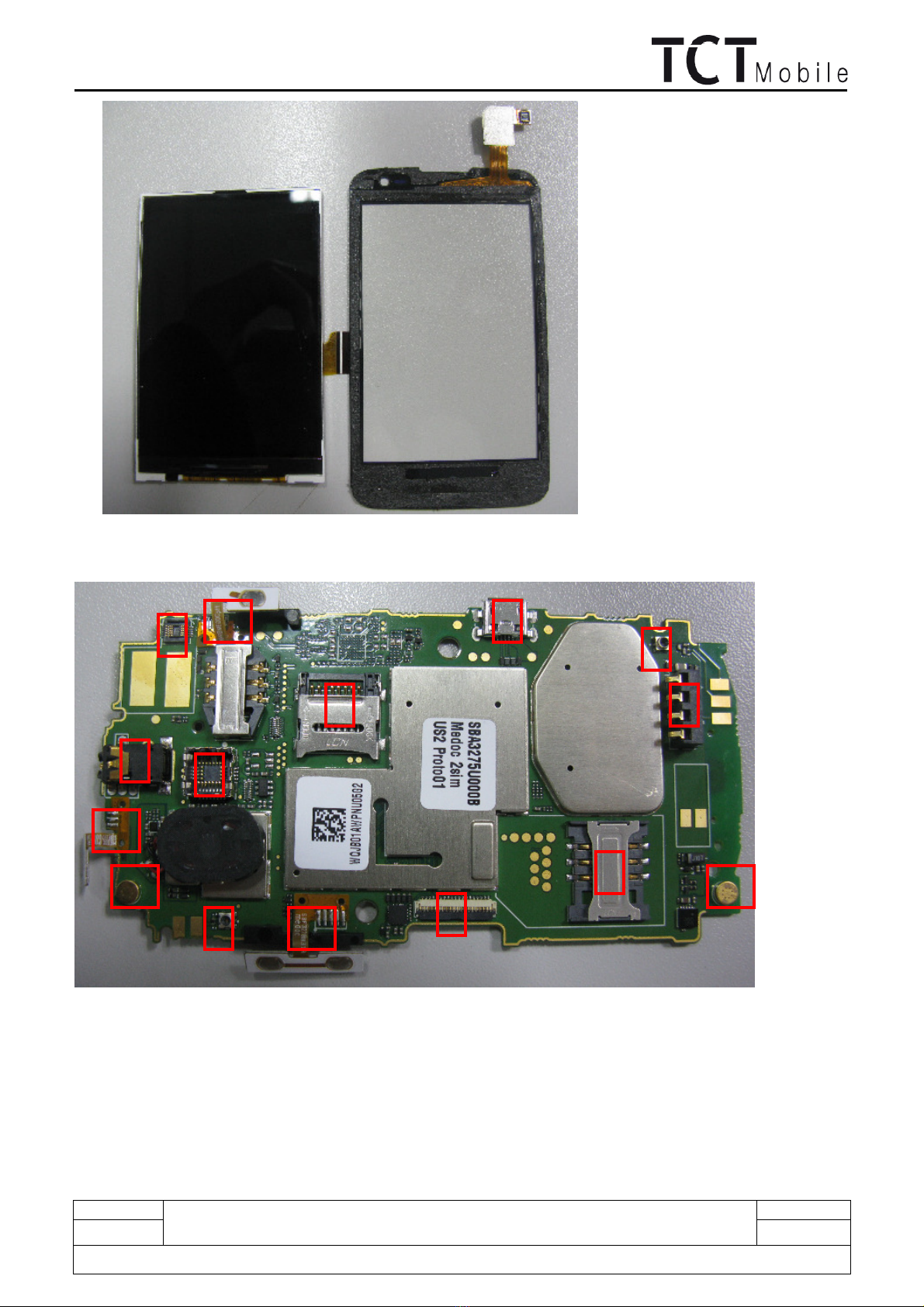
Step 3
:
Remove Touch Lens and LCD Module FPC connector by Plastic Flake

ByNCKTeam
L2 Repair Document
Rev. Page
1.0 ONE TOUCH 985 Level 2 Repair Document 16/31
All rights reserved. Transfer, copy, use and communication of this file is prohibited without authorization.
Step 4: Separate the Main PCBA from Furnished front casing

ByNCKTeam
L2 Repair Document
Rev. Page
1.0 ONE TOUCH 985 Level 2 Repair Document 17/31
All rights reserved. Transfer, copy, use and communication of this file is prohibited without authorization.
.
Step 5
:
Extract the camera by camera jig.
Step 6
:
Please use hot wind gun heating around the edge of the touch lens, then separate the touch
lens from furnished front casing. (Temperature: 00
±10℃, Air Level:3, Height:5-10mm, Time:30s)

ByNCKTeam
L2 Repair Document
Rev. Page
1.0 ONE TOUCH 985 Level 2 Repair Document 18/31
All rights reserved. Transfer, copy, use and communication of this file is prohibited without authorization.
Step 8: If you find the top of the touch screen is too viscous when you separate the touch screen
from furnished front casing by plastic flake, please first prop the touch screen up by plastic pen and
pay attention the place of TP FPC.

ByNCKTeam
L2 Repair Document
Rev. Page
1.0 ONE TOUCH 985 Level 2 Repair Document 19/31
All rights reserved. Transfer, copy, use and communication of this file is prohibited without authorization.
Step 9
:
Separate the LCD Module from Touch lens by Plastic Flake.
ByNCKTeam
L2 Repair Document
Rev. Page
1.0 ONE TOUCH 985 Level 2 Repair Document 20/31
All rights reserved. Transfer, copy, use and communication of this file is prohibited without authorization.
Step 0: Remove the following components from main PCBA with hot wind gun.
1-
Touch panel Module connector 2-battery connector 3-SIM connector 4- F connector 5-USB
connector 6-T flash connector 7-camera connector 8-LCD module connector 9-audior jack 10-
volume side key FPC 11- Power side key FPC 12-Microphone 13-Camera key FPC
1
3
2
5
4
6
8
10
7
9
12
13
11
4
12

ByNCKTeam
L2 Repair Document
Rev. Page
1.0 ONE TOUCH 985 Level 2 Repair Document 21/31
All rights reserved. Transfer, copy, use and communication of this file is prohibited without authorization.
Disassembly Notice:
Put all the spare parts on right position (don’t let all spare parts mixed and put on the clean place to
avoid vitiated or stained for each spare part) after disassembly. When taking apart of LCD, take care
not to dirty or damage it.
4.4 Reassembly Process
Please make reference to the disassembly process for assembly reverse an order of the disassembly
steps.
Attention: Insert main FPC and assembly main PCBA with furnished keypad casing, lock the main FPC
connector to PCBA connector, and then place the side key, Assembly the furnished frame. Note the
orientations of the main FPC.

ByNCKTeam
L2 Repair Document
Rev. Page
1.0 ONE TOUCH 985 Level 2 Repair Document 22/31
All rights reserved. Transfer, copy, use and communication of this file is prohibited without authorization.
4.5Disassembly process evaluation
We list the ONE TOUCH 985 parts disassembly time, technique levels and disassembly methods as below,
for technique levels, Class 1 signifies easy to disassembly, Class 2 signifies normal to disassembly and
Class 3 signifies hard to disassembly.
spare part Time
for
disassembl
y
Jigs for
disassembly
Difficu
lty Class
Remark
battery cover 3s Plastic Flake Class 1
Furnished casing with
screws
20 screwdriver Class 1
PCBA 20s Plastic Flake Class 1
Volume key 5S Tweezers Class 1
Power key 5S Tweezers Class 1
Antenna Module 20S Tweezers Class 1
Speaker 10s Soldering iron Class 1
Camera module 10s Camera jig Class 1
volume key FPC 15s Hot wind gun
screwdriver
Class 2
Power key FPC 15s Hot wind gun
screwdriver
Class 2
Receiver 10s Tweezers Class 1
Receiver mylar 10s Tweezers Class 1
PS rubber 5s Tweezers Class 1
Vibrator 5s Tweezers Class 1
LCD Module 20s Plastic Flake Class 2
LCD connector tape 20s Tweezers Class 2
TP FPC tape 20s Tweezers Class 2
Be careful for
main PCBA pad
and LCD FPC
damage
BTB connector socket
60s Hot wind gun
Tweezers
Class3
The connector is
easy to be
damaged
RF swithch
60s Hot wind gun
Tweezers
Class3
The connector is
easy to be
damaged
USB connector
60s Hot wind gun
Tweezers
Class3
The connector is
easy to be
damaged
2 in 1SIM card connector
120s Hot wind gun
Tweezers
Class 3
The connector
is easy to be
damaged
audio jack 60s Hot wind gun
Tweezers
Class3
The connector is
easy to be
damaged
flash card connector 120s Hot wind gun
Tweezers
Class 3
The connector
is easy to be

ByNCKTeam
L2 Repair Document
Rev. Page
1.0 ONE TOUCH 985 Level 2 Repair Document 23/31
All rights reserved. Transfer, copy, use and communication of this file is prohibited without authorization.
damaged
Battery connector 40s Hot wind gun
Tweezers
Class3
The connector
is easy to be
damaged
Microphone 40s Hot wind gun
Tweezers
Class3
LED 60s Soldering iron
Tweezers
Class3
Keypad film 20s Tweezers Class 2
4.6Disassembly Complete
5 Level 2 repair
This chapter describes the LEVEL 2 repair that can be done without any diagnostic equipment.
Problem description Action And Solution
Charging Bad
or
No Charge
1.Check voltage of the battery: if 0V,
charge some minutes and check the
charge indicator;
2.Check the battery contact, change the
battery connector if broken;
3.Check the charge plug on B cover,
change it if necessary;
Switch on with
battery power
Can ‘t Switch on 1.Check voltage of the battery;
2.Check the battery contact, change the
battery connector if broken;

ByNCKTeam
L2 Repair Document
Rev. Page
1.0 ONE TOUCH 985 Level 2 Repair Document 24/31
All rights reserved. Transfer, copy, use and communication of this file is prohibited without authorization.
3.Check the power on key;
4.Check BTB connector socket pin
Main display Missing line or column; no
display; bad or no LCD
backlight
Check Connection flex (FPC
cable),change it if necessary;
Replace display module if necessary;
Vibrator The vibrator does not work Check the contact on the PCBA (dirty or
oxidized), replace the vibrator if
necessary;
Network Problem No emission or No reception
Check the antenna contactor on the B
cover;
Check the contact on the PCBA (dirty or
oxidized);
TF card No communication between
the phone and the TF card
Check the TF connector on the PCBA;
Camera Camera doesn't work Check camera module
Check also camera socket broken or
not
Audio Bad or no emission (TX
audio from mobile);
Bad or no reception (RX
audio on mobile);
Hands-free problem;
Key beep and melody
problem
Check microphone, replace it if
necessary;
Check the contact on the PCBA (dirty or
oxidized)
Check loud speaker, replace it if
necessary;
Check the contact on the PCBA (dirty or
oxidized)
In case the LEVEL 2 repair can’t solve the problem, or the PCBA is damaged, exchange the PCBA.
6 PCBA exchange
If Level 2 repair does not solve the failure, it is mandatory to change the PCBA and follow the process as
below.
1) Collect the PCBA (without accessories, LCD and camera), with microphone and vibrator.
2) Get a new PCBA from the swap stock. Reuse those accessories to assemble the mobile.
3) Fill in the record sticker with IMEI number, fault code, short code, Hardware Technical Level and
software version.
4) Send the NG PCBA with record sticker back to L3 repair center with the recommended packaging
method,
Note: packaging method please refer item “12. Packaging requirement”.

ByNCKTeam
L2 Repair Document
Rev. Page
1.0 ONE TOUCH 985 Level 2 Repair Document 25/31
All rights reserved. Transfer, copy, use and communication of this file is prohibited without authorization.
7 Other component exchange
The other components exchange such as
1) LCD module
2) Vibrator
3) Receiver
4) Speaker
5) Microphone
6) Camera
7) FPC connection
8) Audio connector
9) Camera connector
10) Other related mechanical components
Please follow the detail steps 4.3 (Disassembly and assembly process).
But need to be very careful to handle the components with related special tool or jig (especially replacing
new components)
It is better to handle it with plastic tools (plastic tweezers and wedge etc.).
Besides operator must wear anti-static gloves, fingertips or wear static loop during the whole process of
components exchange.
8 Final test
8.1 Function Test
During the function test, the following items must be checked and validated.
1) Cosmetic aspect of the handset,
2) The Software Technical sticker state on the Board
3) Switch on the handset
4) Default welcome message
5)
Press *#2886# on the idle screen to start the auto test

ByNCKTeam
L2 Repair Document
Rev. Page
1.0 ONE TOUCH 985 Level 2 Repair Document 26/31
All rights reserved. Transfer, copy, use and communication of this file is prohibited without authorization.
8.2 Measurement
Measurements Channel Power
level
Tol.min Tol.max
Condition
GSM
Connection Mobile 63* 9 None None Radiated meas
Call base from mobile 5* 9 None None Radiated meas
Power level measurements 5* 9 22 dBm 28 dBm
Radiated meas
Power level measurement 5* 5 31 dBm 35 dBm
Radiated meas
Peak Phase error
measurements 5* 5 0° 20° Radiated meas
RMS Phase error
measurements 5* 5 0° 5° Radiated meas
Frequency error
measurements 5* 5 -90 Hz +90 Hz Radiated meas
RX Level (BS power level : -
60dBm) 5* 5 45 55 Radiated meas
Power level measurements 120* 5 31 dBm 35 dBm
Radiated meas
Peak Phase error
measurements 120* 5 0° 20° Radiated meas
RMS Phase error
measurements 120* 5 0° 5° Radiated meas
Frequency error
measurements 120* 5 -90 Hz +90 Hz Radiated meas
RX Level (BS power level : -
60dBm) 120* 5 45 55 Radiated meas
This manual suits for next models
3
Table of contents
Other TCT Mobile Telephone manuals


