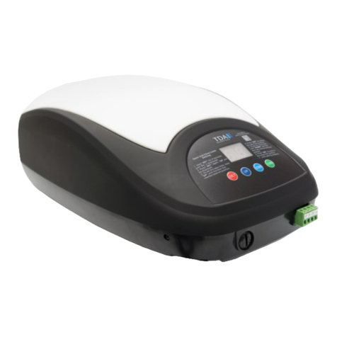
TdA DKC1500 Series User manual

SLIDING GATE OPERATOR
USER’S MANUAL
MODEL: DKC1500/DKC1500Y
WARNING!
ONLY QUALIFIED AND EXPERIENCED TECHNICIANS
SHOULD ATTEMPT INSTALLATION OR SERVICE TO
THIS UNIT, OTHERWISE, SERIOUS PERSONAL
INJURY, DEATH, OR PROPERTY DAMAGE MAY
OCCUR.
PLEASE KEEP THESE INSTRUCTIONS FOR
FURTHER REFERENCE.
Total Door Automation (Australia) Pty Ltd
www.totaldoorautomation.com.au
sales@totaldoorautomation.com.au

DKC1500 SERIES SLIDING GATE OPERATOR USER’S MANUAL
2
OUTLINE
1. Important safety information………………………3
2. Main features ……………………………………3
3. Technical parameters ……………………………3
4. Working principle and main structure ……………4
5. Manual operation ………………………………4
6. Packing list ………………………………………4
7. Installation and adjustment ………………………5
8. Electrical …………………………………………9
9. Control …………………………………………11
10. Maintenance ……………………………………13

DKC1500 SERIES SLIDING GATE OPERATOR USER’S MANUAL
3
1.Important safety information
Carefully read and follow all safety precaution and warnings before attempting to install and use
this operator, incorrect installation can lead to severe injury.
The gate operator should be installed by a qualified technician; otherwise, serious personal
injury or property damage may occur.
When opening or closing the gate, do not attempt to walk or drive through the gate.
Children should not be allowed to play near or operate automatic gates.
Keep remote controls away from children, to prevent the gate operator from being activated
involuntarily.
Warning: High voltage in the control box, the control box should be switched off before
repairing it or opening its cover.
The gate operator must be grounded.
Install the gate operator on the inside of the property, DO NOT install it on the outside of the
property where the public has access to it.
Be careful when in close proximity to moving parts where hands or fingers could be
pinched.
It is necessary to install the located blocks on two ends of guide.
Do not allow control devices to be placed so that a person can access them by reaching
through the gate.
In the event of power failure, an emergency release key allows you to operate the gate
manually.
Keep control box away from sunlight and rainwater
Do not change the opening & closing speed arbitrarily.
The operator should be switched off before repairing it or opening its cover.
2. Main features
The device is used to drive the sliding gate and retractable door.
For your safety, the operator will stop if it was obstructed.
Supports up to 40 remote controls.
Infrared terminal (N.C) is supplied to use.
Auto-close feature is available for this operator.
Over-heat protection.
Manual key release design for emergency purposes.
3. Technical parameters
Type
DKC1500
DKC1500Y
Control
Control box
Integration control board
Power supply
AC240V, 50Hz
Motor power
650W
Motor speed
1400 rpm
Gate moving speed
12m/min(19 teeth); 14m/min (24 teeth)
Output gear
19 teeth (24 teeth, optional)
Output torque
35 N.m
Max. door weight
1800Kg
Reduction ratio
1:30

DKC1500 SERIES SLIDING GATE OPERATOR USER’S MANUAL
4
4. Working principle and main structure
The device is composed of a single-phase motor, worm and worm gear. The main shaft of the
motor rotates the worm with the clutch engaged, the worm rotates the worm gear and output
gear, which pushes rack attached to the sliding gate, thus moving the gate. The dimension is
shown in Fig.1.
Fig.1
5. Manual operation
In case of power failure use manual release key to open or close gate manually, use the release
key as follow:
Fit the release key in the lock.
Turn the key about 4-6 circles anticlockwise.
Open or close the gate manually.
Note: If the gate bumps the mounting post and cannot be electric opened, move the gate a few
inches by hand, thus you can release the gate with the key, open or close the gate manually.
Fig.2
6. Packing list
After receiving the product, you should make an unpack-inspection, in which you should check
whether the product was damaged. If you have any problem please contact our sales agent. You
should find the following items in our standard packing:

DKC1500 SERIES SLIDING GATE OPERATOR USER’S MANUAL
5
NO.
Item
Diagram
Quantity
1
Plates for mounting operator
2
2
Anchor bolts for mounting operator
4
3
Magnet
2
4
High & low bracket
1
5
Block
1 (optional)
6
Release key
2
7
Remote control
2
7. Installation and adjustment
Fig.3
The DKC1500 series rack-driven gate operator operates by forcing a drive rack past a drive gear.
The entire configuration is shown in the diagram below.

DKC1500 SERIES SLIDING GATE OPERATOR USER’S MANUAL
6
40mm
15~25mm
Fig.4
Conduit
In order to protect the wires, conduit must be preset into the concrete when it is poured. Wires
within the conduit shall be located or protected so that no damage can result from contact with
any rough or sharp part. If you have installed an external button switch, we advise you to use
two conduits: one for main power wire, another one for control wire. Always separate power
wires from control wires.
Concrete pad
The base unit of the gate operator requires a concrete pad in order to maintain proper stability.
The concrete pad should be approximately 400mm x 250mm x 200mm deep in order to provide
for adequate operation.
Anchors
You can use the anchor bolts, anchors, washers, and nuts. These anchors must be set into the
concrete when it is poured, or you can use wedge anchors.
Fig.5

DKC1500 SERIES SLIDING GATE OPERATOR USER’S MANUAL
7
1~2mm
Operator Base
Mount the gate operator base to the concrete pad.
Operator
Mount the gate operator to the base using nuts and washers. Verify that the operator is leveled
properly.
Installation of Rack (see Fig.6)
Fix the three nuts (in the same package with rack) on the rack element.
Lay the first piece of rack on the gear and weld the first nut on the gate.
Move the gate manually, checking if the rack is resting on the gear, and weld the second
and the third nut.
Bring another rack element near to the previous one. Move the gate manually and weld the
three nuts as the first rack, thus proceeding until the gate is fully covered.
When the rack has been installed, to ensure it meshes correctly with the gear.
The space between rack and gear is about 1-2mm.
Fig.6
Magnets for limit switch
Install the magnet as shown in Fig.7 and Fig.8 below. The magnet and limit switch are used to
control the position of the gate.
When the magnet is installed, release the gear clutch and push the sliding gate manually to
pre-determine the position. Weld the magnet bracket to the rack and then tighten the gear clutch.
The lower bracket is for open position and higher bracket is for close position. Finally adjust the
magnet to the proper position by moving the gate with the motor. The magnet should be
10~15mm away from the magnetic limit switch. If it is too far away, the switch will fail to work.
Adjust the position of the magnetic limit switch until the positions of the opening and closing
meet the requirement.
Lower bracket
Rack Magnet
Higher bracket
Weld
It can be adjusted
Fig.7

DKC1500 SERIES SLIDING GATE OPERATOR USER’S MANUAL
8
19 teeth:122mm
24 teeth:132mm
10~15mm
19 teeth:122mm
24 teeth:132mm
30~35mm
Fig.8
Spring for limit switch
Install the magnet as shown in Fig.9 and Fig.10 below.
To ensure safety, it is recommended to install limit devices at both ends of the gate to prevent
the gate from sliding out of the rails. The rails must be installed horizontally.
Install the plastic block as shown in Fig.7 and a Fig.8. The spring limit switch and blocks are
used to control the position of the gate.
Release the gear clutch with the key and push the sliding gate manually to pre-determine the
position, fix the block to the rack and then tighten the gear clutch with the key. Moving the gate
electrically, adjust the block to the proper position until the position of the opening and closing
meet the requirement.
Rack
Left block Right block
Screw the blocks on rack
Fig.9
Fig.10

DKC1500 SERIES SLIDING GATE OPERATOR USER’S MANUAL
9
8. Electrical
Make sure that the power is OFF before making any electrical connections. Remove the cover of
the control box, perform the wiring and replace the cover again. (Refer to Fig.11 control board
scheme and wiring notes)
Fig.11 KZB14-2 Control board scheme

DKC1500 SERIES SLIDING GATE OPERATOR USER’S MANUAL
10
Wiring notes for control board
1. Fuse:5A, φ5x20(250V),
2. Power supply: E(Ground), N(Neutral ), L(Live), AC240V
3. Motor: U (Com), V (Positive direction), W (Opposite direction), E (Earth)
4. Capacitor
5. Alarm Lamp (not supply): AC240V
6. Force Adjustor (VR2): Clockwise +, Counterclockwise –
7. Force Adjustor (VR1): Clockwise +, Counterclockwise –
8. DIP-switch
9. Learn button: LEARN
10. Indicator light (learn): LED2
11. Receiver
12. MCU: stm8s103
13. Limit switch(N.C.) : OP(open),GND(com), CL(close),
Snip short wire ‘S2’, Limit switch : N.O.
OP
GND
CL
Wiring
Open
Com
Close N.C. (for N.C. limit switch)
Open
Com
Close
Control
board
Open limit
Com
Close limit
N.O. (for N.O. limit switch)
Limit switch mode is adjustable by DIP switch.
14. Output power supply: 12V(DC 12V), GND(COM), DET(Loop detector), IR( Infrared
photocell)
12V
IR
GND
DET
Safety device
Control board
12V
Infrared
Com
Loop detector
15. Power indicator light: LED1
16. External button switch: P(Pedestrian mode), OSC(Keypad), GND(Com), G (Close),T
(Stop), K(Open)

DKC1500 SERIES SLIDING GATE OPERATOR USER’S MANUAL
11
P
OSC
GND
G
T
K
P
OSC
GND
G
T
K
Pedestrian
Keypad
Com
Close button
Stop button
Open button
Schematic diagram Wiring diagram
Control board External button switch
17. Transformer: 220V/10V 5W
9. Control
Button 3
Button 4
Button 2
Button 1
Fig.12
Adding extra remote controls (learn): Press the button ‘LEARN’ about 1 second(See Fig.12
terminal 9) on the control board, release the button till the ‘LED2’ turns on, then press the
same remote control button which you want to use twice, the ‘LED2’will flash several times
and then turn off, The learning process is finished.
Up to 40 remote controls may be used.
Erase remote controls: To erase all existing remote controls, press and hold ‘LEARN’
button about 8 seconds till the ‘LED2’turns on and turns off. This indicates that all the
remote controls have been erased completely.
Warning: For safety and security, we recommend that the factory setting be
replaced with a personal code.
The remote control works in three channel mode. See Fig.12. Button 1 - open the gate,
button 2-close the gate, button 3- stop the gate, button 4- pedestrian mode
Warning: Notify the users that the gate is never to be operated unless it is in full view.
Verify open direction: If the gate does not move in the desired direction, then you will need
to reverse the motor operating direction, you can do this by exchanging wires ‘V’and ‘W’,
‘OP’ and ‘CL’.
Exchange wires ‘OP’ and ‘CL’ if the limit direction is wrong.
WARNING: Do not attempt to tune the gate by placing your hand, arm or other body part in the

DKC1500 SERIES SLIDING GATE OPERATOR USER’S MANUAL
12
path of the gate, as serious injury could result. Damage to the gate operator motors may also
occur by placing a heavy immovable object in the path during the testing phase. Instead, place a
light object in the path (e.g., a chair or trash can) which can be pushed out of the way without
causing damage to gate motors. Once the tuning is complete you may replace the cover.
External button switch (not included): two different modes you can select according
to your order.
Three-button external button switch: connect external button switch to terminal ‘K’, ‘T’, ‘G’
and ‘GND’. Press ‘OPEN’button, the gate will open. Press ‘STOP’button, the gate will stop.
Press ‘CLOSE’button, the gate will close.
Single-button/keypad: connect keypad to terminal ‘OSC’and ‘GND’, with each press of the
button, the gate will close, stop, open or stop cycle.
Auto-close function: This feature can be selected to make the gate stay open for some
seconds before it automatically closes. The auto-close time can be adjusted by DIP-switch.
Auto-close time
1second
10 seconds
30 seconds
Auto close function is
unavailable
Position 1
ON
OFF
ON
OFF
Position 2
OFF
ON
ON
OFF
WARNING: Infrared photocell must be used.
Pedestrian mode: Connect the pedestrian button switch to ‘P’and ‘GND’terminal on the
control board. Set auto close time first (auto-close time can be adjusted by DIP-switch),
press the button 4 of remote control or pedestrian button switch, the gate will open about
1.2 meters for people pass through, after passing through the gate, the gate will close
automatically.
Adjustment of opening & closing force: rotate the ‘VR1’ (See Fig.11 terminal 7) knob
with a screwdriver to adjust opening & closing force, the force may be increased (or
decreased) by rotating clockwise (or counterclockwise). If you turn the variable resistor
clockwise it will increase force. If you turn the variable resistor counterclockwise, it will
decrease force.
Adjustment of soft stop width: Rotate the ‘VR2’knob (See Fig.11 terminal 6) to adjust soft
stop width, the width may be increased by rotating clockwise (soft stop width: 0-40cm
adjustable).
Infrared photocell (not included): If infrared beam is interrupted during closing, the gate
will reverse and go open immediately. Connect infrared photocell to terminal ‘IR’and ‘GND’
on the control board. Short ‘IR’and ‘GND’if infrared photocell is not used.
Open priority: The gate will return to open if press ‘OPEN’button of external button switch
during closing.
Loop detector: connect loop detector (N.O.) to terminal block ‘DET’and ‘GND’.
If loop detector detects vehicles during closing, the gate will open immediately and stay
open until the vehicles move out of the loop. After vehicles move out of the loop, the gate
will continue to close.
If loop detector detects vehicles when the gate stops, the gate will open immediately until
vehicles move out of the loop. After vehicles move out of the loop, the gate will close.
Soft start: snip the short wire ‘S3’, the gate will start softly.

DKC1500 SERIES SLIDING GATE OPERATOR USER’S MANUAL
13
Over- heat protection: The device is equipped with a thermal protector. The motor is only
designed to continuous work for less than 15 minutes. If it is runs continually for an
extended period of time, a thermal protector will stop it because of the high temperature.
10. Maintenance:
Ensure the operator is well earthed, and correctly terminated.
Regularly grease the wheels and axles to ensure the gate moves smoothly.
Ensure the power is switched off before removing the cover.
Keep operator clean at all times.
This manual suits for next models
2
Table of contents
Other TdA Garage Door Opener manuals
Popular Garage Door Opener manuals by other brands

dtm
dtm GO801/1001 Assembly manual

Chamberlain
Chamberlain 3585-100 3/4 HP owner's manual

Chamberlain
Chamberlain LiftMaster Professional Security+ 3800 owner's manual

Maximum Controls
Maximum Controls MATRIX III MAX 1500 PRO installation guide

CAME
CAME VER Series installation manual

Genie
Genie Pro Stealth owner's manual