TdA FBD120 User manual

SECTIONAL GARAGE DOOR OPENER
FBD120/180/200/220
Installation and Users Manual
Total Door Automation (Australia) Pty Ltd
www.totaldoorautomation.com.au
sales@totaldoorautomation.com.au
Technical Support 1800 AUSTDA (1800 287 832)
WARNING
ONLY QUALIFIED AND EXPERIENCED TECHNICIANS
SHOULD ATTEMPT INSTALLATION OR SERVICE TO THIS
UNIT, OTHERWISE, SERIOUS PERSONAL INJURY, DEATH,
OR PROPERTY DAMAGE MAY OCCUR.
SAVE THESE INSTRUCTIONS.

FBD120/180/200/220 SECTIONAL GARAGE DOOR OPENER
2
TABLE OF CONTENTS
Safety Instructions 3
Main Features 4
Technical Parameters 4
Preparation before Installation 5
Packing List
Tools needed for Installation
Installation and Adjustment 6
Interface 10
Pushbuttons
Transmitters
Programming 11
Open and Close Limit
Adjusting Obstruction Force Sensitivity
Infrared Photocell
Automatic Closing
Door Lock Mode
Adding Extra Transmitters
Delete Transmitters
External Terminal Connections 18
Maintenance 19
Troubleshooting 19

FBD120/180/200/220 SECTIONAL GARAGE DOOR OPENER
3
1. Safety Instructions
THESE ARE IMPORTANT SAFETY INSTRUCTIONS. FOLLOW ALL INSTRUCTIONS AS
INCORRECT INSTALLATION CAN LEAD TO SEVERE INJURY OR DEATH
Installation and wiring must be in
compliance with your local building and
electrical codes. Connect the power
supply cord only to properly earthed
mains.
The door opener should be installed and
put into operation by qualified
personnel. Otherwise, serious personal
injury or property damage may occur.
No one or vehicle is allowed to enter or
leave the garage while the remoter is
being installed, do not allow children to
play near the door.
Before installation of the door opener,
the door should be carefully checked for
being kept well balance. The door must
be in good working order. Open and
close the door manually, make sure the
door can be moved smoothly.
The door opener must be earthed.
Our company reserves the right to
change the design and specification
without prior notification.
Install and adjust the manual
release so that the handle hangs
less than 1.5m above the floor.
The door should only be operated when
it can be observed to avoid accidents.
When opening or closing the door, do
not attempt to walk or drive through the
door.
The operator may only be repaired
with the door closed.
The operator should be disconnected
from mains power to avoid electrical
shock before repairing it or opening its
cover.
Locate any fixed control: within sight of
door but away from all moving parts of
the door and at a height of more than
1.4m above the ground to avoid children
reaching it. Keep remote controls away
from children, to prevent the door
opener from being activated
involuntarily.
WARNING: Important safety instructions. It is important for the safety of
persons to follow all instructions. SAVE THESE INSTRUCTIONS.
Failure to comply with the instructions
above may result in personal injury or
property damage. Our company does
not accept responsibility for damage
or injury resulting from installing this
operator.

FBD120/180/200/220 SECTIONAL GARAGE DOOR OPENER
4
2. Main Features
The door opener is designed for garage door.
The control unit regulates all the necessary functions include automatic
lighting control, automatic memory, automatic close, automatic reverse and
photocell protection etc.
Courtesy light will turns on and off after 3 minutes.
The operator memorizes the limit positions and unique braking system that
slows the unit down at the end of its travel. Soft start and soft stop control
guarantees extremely smooth and quiet operation.
Automatic reversion on obstruction during closing procedure.
The controller has a security LOCK function which prevents operation of the
door from transmitter.
In the event of power failure, the release device makes it possible to open and
close the door manually.
Hopping code remote control with max. 30 pcs hand transmitters.
Wiring terminals for battery, button switch, infrared photocell etc.
3. Technical Parameters
Model
FBD120
FBD180
FBD200
FBD220
Motor Power
60 W
80 W
100 W
120 W
Lifting Capacity
600 N
800 N
1000 N
1200 N
Max. Door Size
10 m2
12 m2
14 m2
16 m2
Power Supply
AC240V 1ph
Motor
DC24V
Ambient Temperature
-20ºC~+45ºC
Working Humidity
≦90%
Courtesy Light Time
3 minutes
Radio Frequency
433.92 MHz
Transmitter Type
Rolling code
Transmitter battery
27A AC12V
Bulb
AC240V

FBD120/180/200/220 SECTIONAL GARAGE DOOR OPENER
5
4. Preparation before Installation
After receiving the product, you should make an unpack-inspection, in which
you should check whether the product was damaged. If you have any problem
please contact dealer.
Packing list:
Door opener (x1) Shuttle &manual release cord(x1)
Chain drive rail assembly (x1)
Door bracket(x1)
Header bracket (x1)
Straight arm(x1)
Screw/Screw cap/Pin and R pin
Transmitter (x2)
R pin
Pin
Screw(M8x16mm) Screw cap (M8)
L arm (x1)
Screw(M6x22mm) Screw(M6x55mm)
Operator bracket (x3)
Angle iron (x1) 7 shaped angle iron (x2)
Screw cap(M6) Pin (long)
Fig.1
Tools Needed for installation
1
Electric drill and assorted drill bits
2
A ladder
3
Spanner / Wrench
4
Tape Measure and Level Ruler
5
Slotted Screwdriver and Philips Screwdriver
6
Pliers
7
Multimeter / Test pen
8
Hacksaw / Cutter
9
Hammer
FBD120/180/200/220 SECTIONAL GARAGE DOOR OPENER
6
5. Installation and adjustment
Step 1
Before installation of the door opener, the door should be carefully checked for
being kept well balance.
The door must be in good working order. Open and close the door manually,
make sure the door can be moved smoothly.
Check if there is a solid frame in the wall in the center of the door.
Close the door.
Locate the centre of the door
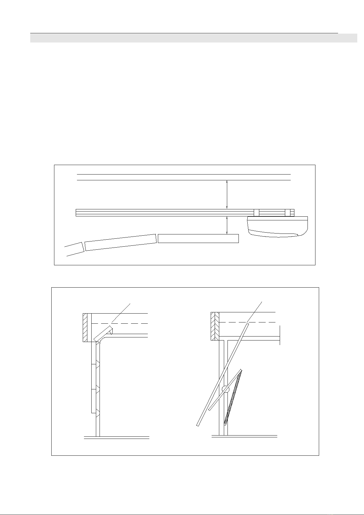
Fit in the drive rail least 40mm space above the highest point of the garage
door. There should be a minimum clearance of 80mm between the drive rail
and the ceiling.
Ensure the header bracket is being installed in the centre position.
Garage door
40mm 80mm
Ceiling
Fig.2
Tilt door
Sectional door
Highest point
Highest point
Fig.3
FBD120/180/200/220 SECTIONAL GARAGE DOOR OPENER
7
Step 2
Insert the shuttle into the groove of the chain drive rail. Ensure it faces the right
direction (the release arm on the shuttle towards the door opener). Fasten the
four screws (M6x22mm).
Straight arm
Pin and R pin (x1)
M6x22mm Screw
(x4)
The release arm towards
the door opener.
Fig.4
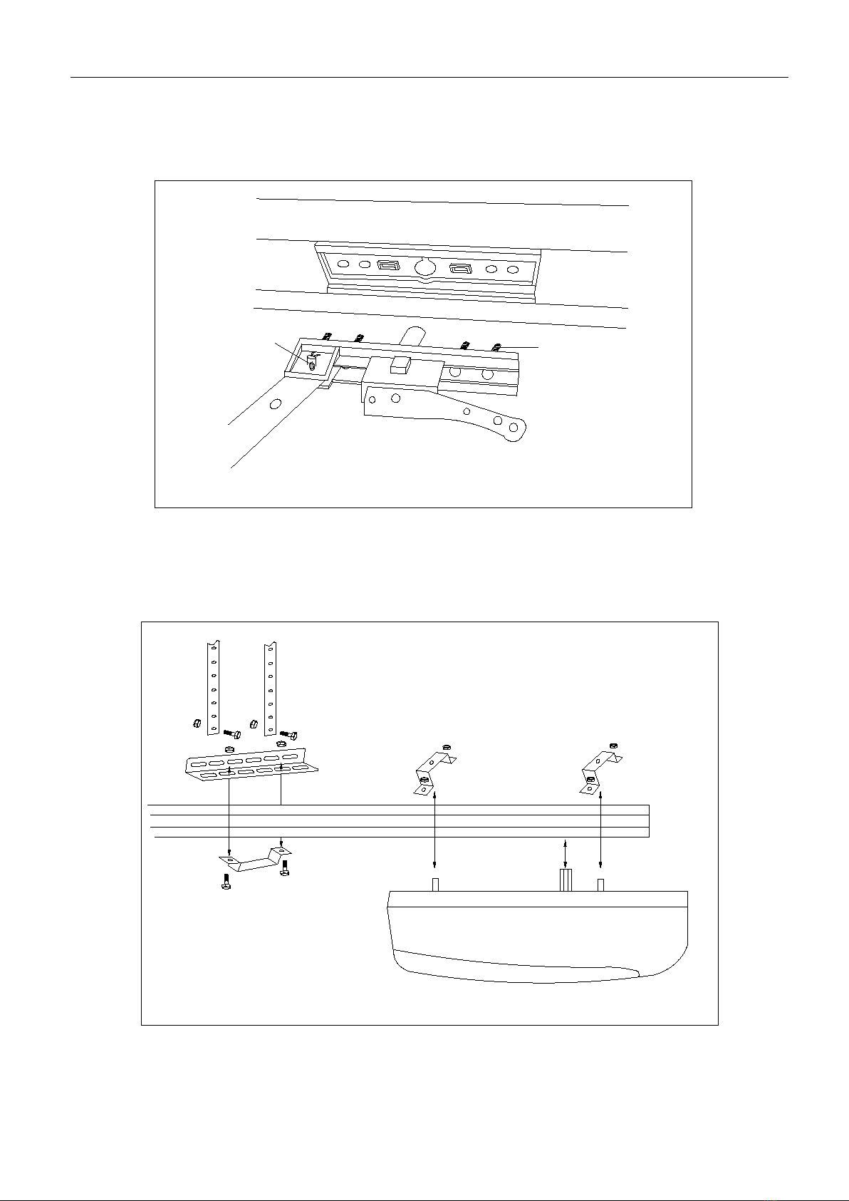
Step 3
Place the opener on the floor. Attach the opener to the chain drive rail, make sure
the spindle is inserted into the chain drive, then fix the brackets.
Steel rail
Operator bracket
Door opener
Angle iron
M8X16m m screw (x2)
M8 screw cap(x2)
M8 screw cap(x4)
7 shaped angle iron(X2)
M6 screw cap(x2)
M6X22m m screw (x2)
Fig.5
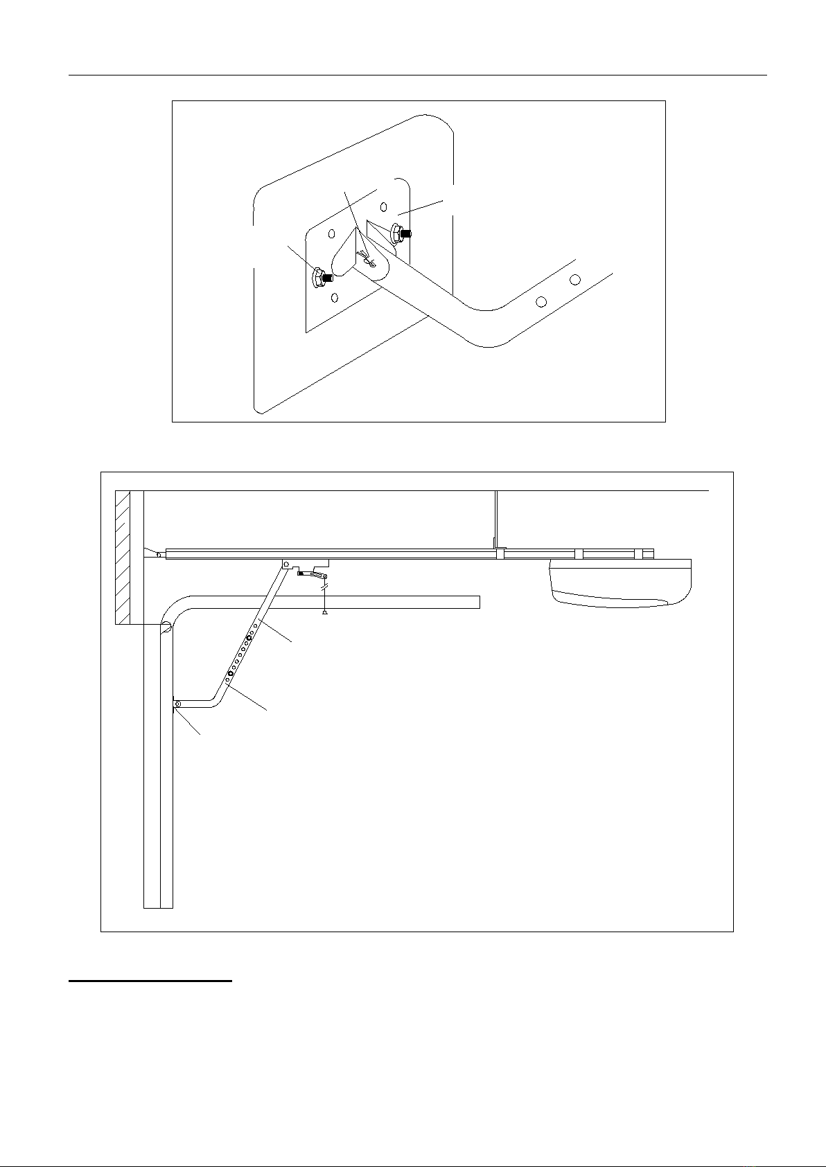
Step 4
Close the door.
Place the opener in the center of the floor. Lift the front end of the rail up to the

FBD120/180/200/220 SECTIONAL GARAGE DOOR OPENER
8
header bracket that has been mounted above the garage door, insert the bolt and
secure it with nut.
Pin(long) and R pin
M8 Expansion bolt (Not
included in accessories)
Header bracket
Fig.6
Step 5
Raise and support the opener with a ladder and line up the rail with the centerline
marked on the door. The rail must be level.
Fix the rail to ceiling with mounting brackets and angle iron see Fig.6, make sure
that the rail is level. Ensure the door does not touch any part of the rail by opening
or closing it.
Fig.7
Step 6
Fix the door bracket on the top edge of the door with screws (M6X55) and screw
caps (M6). Link the L arm to the door bracket with pin and R pin. Link the straight
arm to the shuttle with pin and R pin, then connect L arm to straight arm with two
screws (M8X16) and screw caps (M8), ensure the door arm can be moved freely.
FBD120/180/200/220 SECTIONAL GARAGE DOOR OPENER
9
M8X16mm Screw(X2)
M6x55 screw(X2)
Pin and R pin(X1)
L arm
Door bracket
M8 Screw cap(X2)
M6 screw cap(X2)
Fig.8
Straight arm
Shuttle
L arm
Door bracket
Fig.9
Manual operation
If the door has to be operated manually due to a power failure, pull the release rope,
open and close the door manually. To reconnect the door, move the door by hand
until it engages into the chain shuttle.
FBD120/180/200/220 SECTIONAL GARAGE DOOR OPENER
10
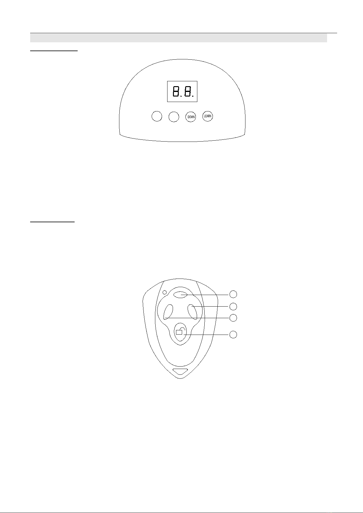
6. Interface
Pushbuttons
SET UP
Fig.10
”SET” button: initiates programming modes & saves the settings.
“UP” button: opens the door; Increase settings in programming mode.
“DOWN” button: closes the door; decreases settings in programming mode.
“LEARN” button: Transmitter code set and clear function.
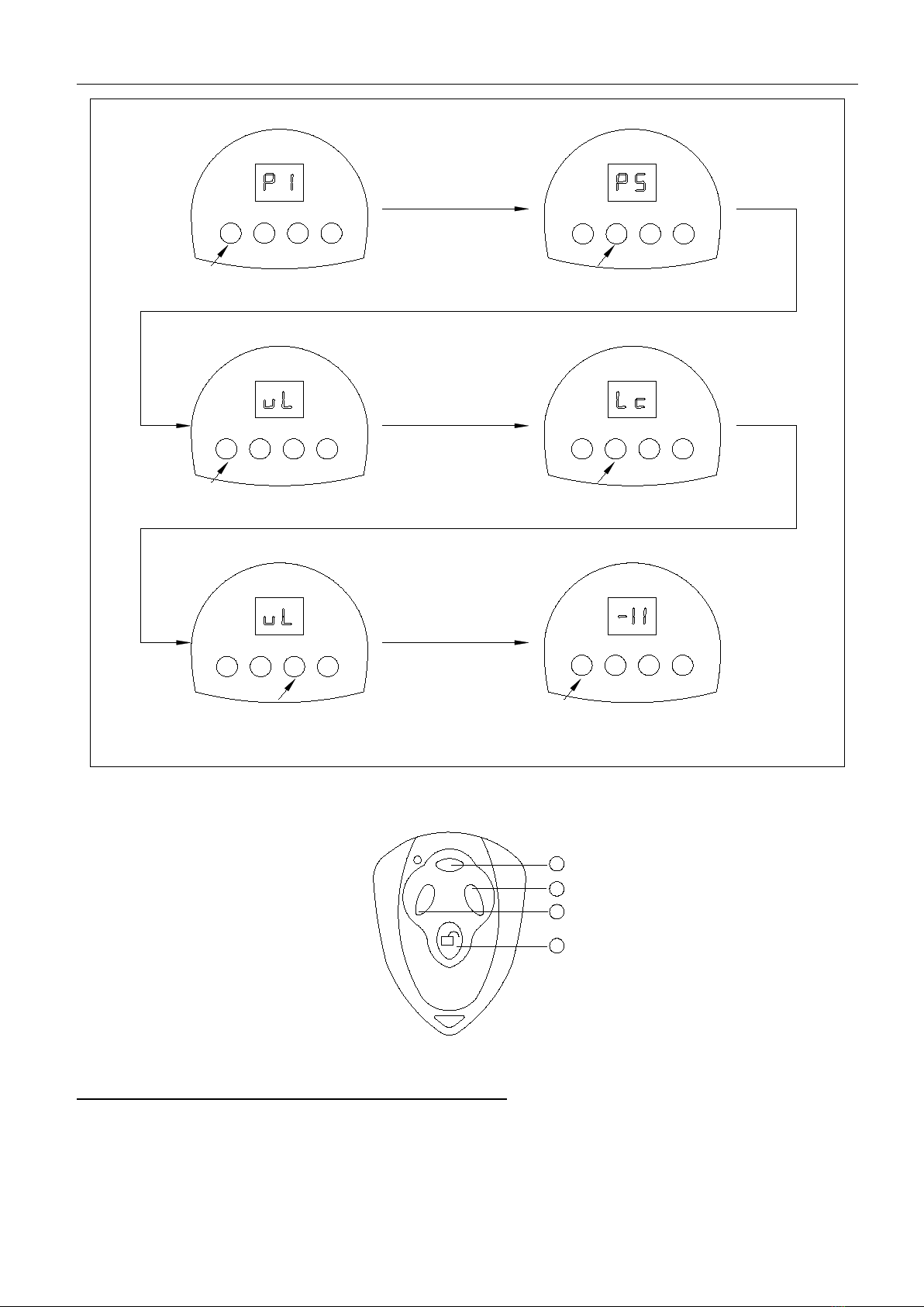
Transmitter
Button 1, button 2, button 3: The transmitter works in a single channel mode.
With each press of the remote control button which has been programmed, the
gate will open, stop, close or stop cycle.
Button 4: LOCK /LIGHT button
1
2
3
4
Fig.11
FBD120/180/200/220 SECTIONAL GARAGE DOOR OPENER
11
7. Programming
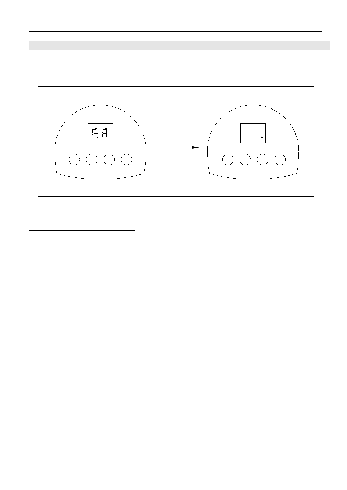
Once the opener is connected to power, the number "88" will be displayed on the LED.
And ‘ . ’ indicates the opener is now on normal status.
SET UP DOWN LEARN SET UP DOWN LEARN
Fig.12
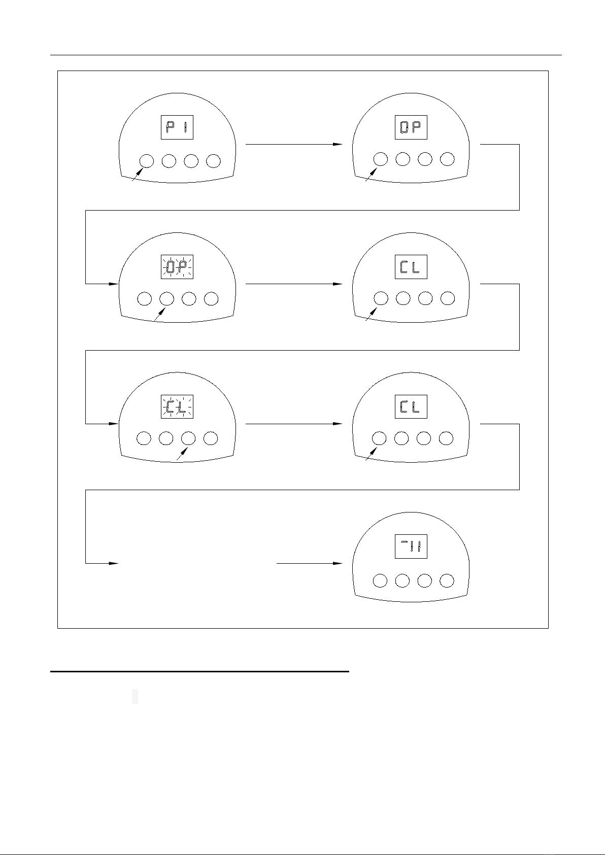
Open and Close Limit (Fig.13)
1. Press and hold “SET” button for 4 seconds until ‘P1’ is displayed.
2. Press “SET” again, ‘OP’ will be displayed.
3. To set open limit, Press and hold “UP” button, ‘OP’ on the LED display will be flashing,
release the button until the door has reached desired position.
4. Press “SET” to confirm the open limit position. the LED will now indicated the ‘CL’
5. To set close limit, press and hold “DOWN” button, ‘CL’ will be flashing, release the button
until the door has reached desired position.
6. Press SET to confirm the close limit position.
7. Limit setting complete.
FBD120/180/200/220 SECTIONAL GARAGE DOOR OPENER
12
5
3
1
6
4
7
2
SET UP DOWN LEARN SET UP DOWN LEARN
SET UP DOWN LEARN SET UP DOWN LEARN
SET UP DOWN LEARN SET UP DOWN LEARN
SET UP DOWN LEARN
The door will do a complete
open and close cycle.
Fig.13
Adjusting Obstruction Force Sensitivity (Fig.14)
If the door meets an obstruction during closing, it will stop and reverse about
15cm~20cm.
1. Press and hold “SET” button for 4 seconds until ‘P1’ is displayed on LED.
2. Press “UP” button, ‘P2’ will be displayed.
3. Press the “SET” button, the opener is now in force adjustment mode.
4. Press “UP” button to increase force setting, maximum force setting is level 9 (F9).
Press “DOWN” button to decrease force, minimum force setting is level 1(F1).
5. Press “SET” button to confirm the setting.

FBD120/180/200/220 SECTIONAL GARAGE DOOR OPENER
13
3
1
4
2
5
SET UP DOWN LEARN SET UP DOWN LEARN
SET UP DOWN LEARN SET UP DOWN LEARN
SET UP DOWN LEARN
Decrease force
Increase force
Fig.14
Infrared Photocell (Fig.15)
1. Press and hold “SET” for 4 seconds until ‘P1’ is displayed.
2. Press “UP” button twice until ‘P3’ is displayed. Press “SET” button to confirm.
3. Press “UP” button (‘H1’ will display) to enable the photocell. Press “DOWN” (‘H0’
will display) to disable the photocell.
4. Press SET to confirm the setting.

FBD120/180/200/220 SECTIONAL GARAGE DOOR OPENER
14
34a
2
1
5
4b
SET UP DOWN LEARN SET UP DOWN LEARN
SET UP DOWN LEARN SET UP DOWN LEARN
SET UP DOWN LEARN SET UP DOWN LEARN
Photocell enable
Photocell disable
Fig.15
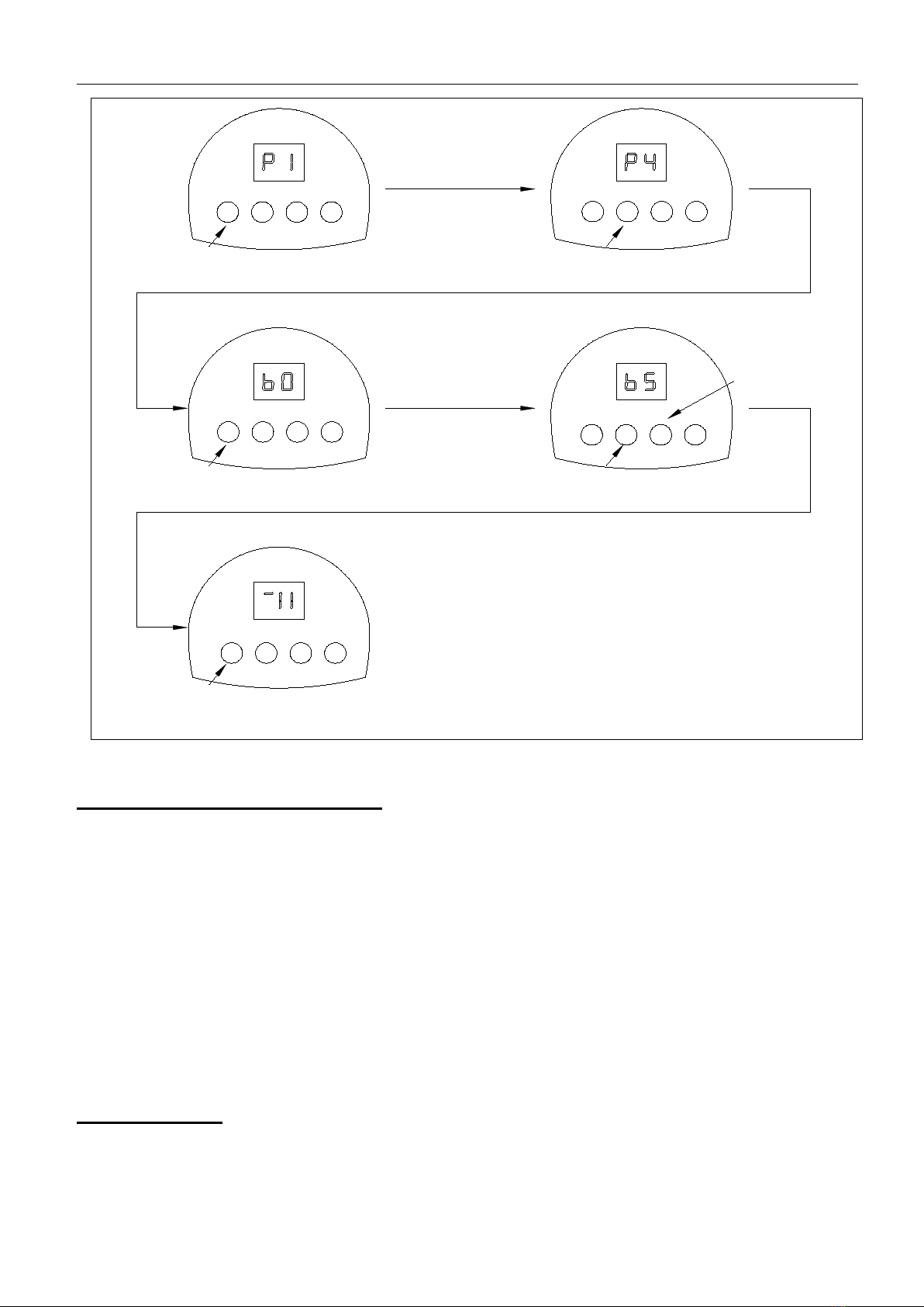
Automatic Closing (1~9 minutes adjustable) (Fig.16)
1. Press and hold “SET” button for 4 seconds until ‘P1’ displayed.
2. Press “UP” button three times until ‘P4’ is displayed on the LED.
3. Press the “SET” button.
4. Press “UP” or “DOWN” to set auto close time (b0-b9). Press “UP” to increase timer,
press “DOWN” to decrease timer.
Note: Set timer to ‘b0’ to disable auto close function.
5. Press SET to confirm the setting.
NOTE: Automatic closing is available only when the door is in fully opened
position.
FBD120/180/200/220 SECTIONAL GARAGE DOOR OPENER
15
2
1
4
3
SET UP DOWN LEARN SET UP DOWN LEARN
SET UP DOWN LEARN SET UP DOWN LEARN
SET UP DOWN LEARN
Decrease time
Increase time
Fig.16
Door Lock Mode (Fig.17, Fig 18)
1. Press and hold “SET” for 4 seconds until ‘P1’ is displayed.
2. Press “UP” button for four times until ‘P5’ is indicated on the LED display. And
press the “SET” button.
3. Press “UP” to enable the door lock (‘LC’ will be displayed). Press “DOWN” to
disable the door lock (‘UL’ will be displayed).
4. Press SET to confirm the setting.
DOOR LOCK function is available only when the door is in fully closed
position.
Once the DOOR LOCK function is set, the transmitter will also be locked. To
operate the garage door, you need to unlock the transmitter first by
pressing the button 4 of the transmitter.
Light function
If you cancel the door lock mode, press button 4 twice, the light will turn on,
press the button 4 once, the light will turn off.
FBD120/180/200/220 SECTIONAL GARAGE DOOR OPENER
16
2
4a
3
1
4b 5
SET UP DOWN LEARN SET UP DOWN LEARN
SET UP DOWN LEARN SET UP DOWN LEARN
SET UP DOWN LEARN SET UP DOWN LEARN
Door lock enable
Door lock disable
Fig.17
1
2
3
4
Fig.18
Adding Extra Transmitter (learn) (Fig.18. 19)
1. Press “LEARN” until “Su” is displayed.
2. Press the same new transmitter button twice.
3. “Of” will be flashing.
4. Learning process is completed when“_11' is displayed.
Up to 30 transmitters can be added.

FBD120/180/200/220 SECTIONAL GARAGE DOOR OPENER
17
1 3
4
2
SET UP DOWN LEARN SET UP DOWN LEARN
SET UP DOWN LEARN
Press the transmitter
button twice.
Fig.19
Delete Transmitters(Fig.20)
1. Press and hold “LEARN” button
2. ‘▬11’ will be displayed, do not release the button and keep holding the “LEARN”
button for 8 seconds until ‘dL’ is flasing.
3. All stored transmitters are being deleted.
3
1
2
SET UP DOWN LEARN SET UP DOWN LEARN
SET UP DOWN LEARN
Fig.20

FBD120/180/200/220 SECTIONAL GARAGE DOOR OPENER
18
8. External Terminal Connections
( B l a c k )
( R e d )
A C 2 4 0V /IN A C 2 40 V /O U T T ra n s fo rm e rL a m p
B utto n sw itch
In fra red p h otoce ll (N .C .)
B a tte ry
M otor
Fig.21
Wicket door(N.C.)
Fig.22
W ic k e t d o o r (N .C .)

FBD120/180/200/220 SECTIONAL GARAGE DOOR OPENER
19
9. Maintenance
Check the garage door every one month to make sure the door is well balanced
and in good working condition.
The auto-reverse function should be regularly inspected, and adjusted if
necessary. For service, call an experienced serviceman. We suggest for safety
reasons, photocells should be installed on doors.
Disconnect from mains power before replacing bulb.
Be sure to read the entire manual before attempting to perform any installation
or service to the door opener.
10. Troubleshooting
Trouble
Possible Causes
Solutions
The door fails to open and
close. LED display does
not light.
1. Power is OFF.
2. Fuse is blown.
1. Make sure the power is
ON.
2. Replace the fuse.
After programmed the
open and close limit, the
motor fails to work.
1. The screws on the hall
(on motor) are loose.
2. Open and close limit.
1. Tighten the two
screws.
2. Reprogram the open
and close limit.
The door can open, but
fails to close.
Infrared photocell function
is enabled, but the
photocell has not been
installed or infrared beam
is obstructed.
Make sure the infrared
photocell function is
disabled. Remove
obstructions or aligning
the transmitter and
receiver.
Transmitter does not
work.
1. Battery level may be
low.
2. Transmitter
1. Replace the battery
inside the transmitter.
2. Re-program the
transmitter.
The transmitter operating
distance becomes short or
indicator light on the
transmitter begins to dim.
Battery level may be low.
Replace battery.
This manual suits for next models
3
Table of contents
Other TdA Garage Door Opener manuals


Popular Garage Door Opener manuals by other brands

E.T. Systems
E.T. Systems DC BLUE ADVANCED Installer's instructions

Nice
Nice ROBO RO 300 Instruction manual and spare parts catalogue

Merlin
Merlin SilentDrive Elite myQ MR865MYQ quick start guide

fadini
fadini MEC 200 LB instruction manual

tau
tau R18 series Use and maintenance manual

tousek
tousek GTZ-Digital Series Mounting and installation manual


