manuals.online logo
Brands
  1. Home
  2. •
  3. Brands
  4. •
  5. TDK-Lambda
  6. •
  7. Power Supply
  8. •
  9. TDK-Lambda EZA2500 Series Installation guide

TDK-Lambda EZA2500 Series Installation guide

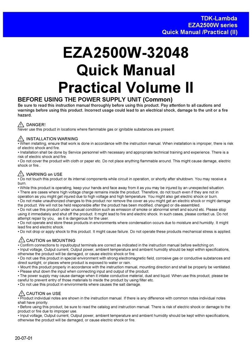
TENTAT
19-11-01
TDK-Lambda
EZA2500 series
Quick Manual /Practical (III)
EZA2500-32048
Quick Manual
Practical Volume III
BEFORE USING THE POWER SUPPLY UNIT (Common)
Be sure to read this instruction manual thoroughly before using this product. Pay attention to all cautions and
warnings before using this product. Incorrect usage could lead to an electrical shock, damage to the unit or a fire
hazard.
DANGER!
Never use this product in locations where flammable gas or ignitable substances are present.
INSTALLATION WARNING
• When installing, ensure that work is done in accordance with the instruction manual. When installation is improper, there is risk
of electric shock and fire.
• Installation shall be done by Service personnel with necessary and appropriate technical training and experience. There is a
risk of electric shock and fire.
• Do not cover the product with cloth or paper etc. Do not place anything flammable around. This might cause damage, electric
shock or fire..
WARNING on USE
• Do not touch this product or its internal components while circuit in operation, or shortly after shutdown. You may receive a
burn.
• While this product is operating, keep your hands and face away from it as you may be injured by an unexpected situation.
• There are cases where high voltage charge remains inside the product. Therefore, do not touch even if they are not in
operation as you might get injured due to high voltage and high temperature. You might also get electric shock or burn.
• Do not make unauthorized changes to this product nor remove the cover as you might get an electric shock or might damage
the product. We will not be held responsible after the product has been modified, changed or dis-assembled.
• Do not use this product under unusual condition such as emission of smoke or abnormal smell and sound etc. Please stop
using it immediately and shut off the product. It might lead to fire and electric shock. In such cases, please contact us. Do not
attempt repair by you, as it is dangerous for the user.
• Do not operate and store these products in environments where condensation occurs due to moisture and humidity. It might
lead fire and electric shock.
• Do not drop or apply shock to this product. It might cause failure. Do not operate these products mechanical stress is applied.
CAUTION on MOUNTING
• Confirm connections to input/output terminals are correct as indicated in the instruction manual before switching on.
• Input voltage, Output current, Output power, ambient temperature and ambient humidity should be kept within specifications,
otherwise the product will be damaged, or cause electric shock or fire.
• Do not use this product in special environment with strong electromagnetic field, corrosive gas or conductive substances and
direct sunlight, or places where product is exposed to water or rain.
• Mount this product properly in accordance with the instruction manual, mounting direction and shall be properly be ventilated.
• Please shut down the input when connecting input and output of the product.
• The power supply may cause damage when it intake conductive material, dust and liquid. When use this product, please be
careful to prevent entry of those materials to inside the product by using filter etc.
• Do not use this product in environments where causes the salt damage.
CAUTION on USE
• Product individual notes are shown in the instruction manual. If there is any difference with common notes individual notes
shall have priority.
• Before using this product, be sure to read the catalog and instruction manual. There is risk of electric shock or damage to the
product or fire due to improper use.
• Input voltage, Output current, Output power, ambient temperature and ambient humidity should be kept within specifications,
otherwise the product will be damaged, or cause electric shock or fire.
- 2 -
TDK-Lambda
EZA2500 series
Quick Manual / Practical (III)
• If the built-in fuse is blown, do not use the product even after replacing the fuse as there is risk of abnormality inside. Be sure
to request repair to our company.
• For products without built-in protection circuit (element, fuse, etc.), insert fuse at the input to prevent smoke, fire during
abnormal operation. As for products with built-in protection circuit, depending on usage conditions, built-in protection circuit
might not work. It is recommended to provide separate proper protection circuit.
• For externally mounted fuse do not use other fuses aside from our specified and recommended fuse.
• This product was made for general purpose electronic equipment for standard industrial use and is not designed for
applications requiring high safety (such as extremely high reliability and safety requirements. Even though high reliability and
safety are not required, this product should not be used directly for applications that have serious risk for life and physical safety.
Take sufficient consideration in fail-safe design (such as providing protective circuit or protective device inside the system,
providing redundant circuit to ensure no instability when single device failure occurs).
• When used in environments with strong electromagnetic field, there is possibility of product damage due to malfunction.
• When used in environment with corrosive gas (hydrogen sulfide, sulfur dioxide, etc.) , there is possibility that they might
penetrate the product and lead to failure.
• When used in environments where there is conductive foreign matter or dust, there is possibility of product failure or
malfunction.
• Provide countermeasure for prevention of lightning surge voltage as there is risk of damage due to abnormal voltage.
• Connect together the frame ground terminal of the product and the ground terminal of the equipment for safety and noise
reduction. If these grounds are not connected together, there is risk of electric shock.
• Parts with lifetime specifications (built-in fan, electrolytic capacitor) are required to be replaced periodically. Set the overhaul
period depending on the environment of usage and perform maintenance. Also, note that there are cases when EOL products
cannot be overhauled.
• Take care not to apply external abnormal voltage to the output. Especially, applying reverse voltage or overvoltage more than
the rated voltage to the output might cause failure, electric shock or fire.
• Do not use in special environment such as places directly exposed to sunlight, dew condensation, moisture, rain, strong
electro-magnetic field, or corrosive gas (hydrogen sulfide, sulfur dioxide).
• This product has a built-in fan for air-cooling. Do not block the air intake and exhaust.
• The output of this product is considered to be a hazardous energy level (The voltage is 2V or more and the power is 240VA or
more). It must not be made accessible to users. Protection must be provided for Service Engineers against indirect contact with
the output terminals and/or to prevent tools being dropped across them. While working on this product, the DC input power must
be switched off and the input and output voltage should be zero.
• When short the output during operation, there is damage inside the converter.
• When change abrupt in Input voltage during operation, there is a Risk of damage inside the converter.
• When use the Electric storage device, Please refer to the manual of electric storage device and use the appropriate protection
device.
Note
• There is a possibility machining traces remain on sheet metal of product.
• Consider storage of the product at normal temperature and humidity avoiding direct exposure to sunlight at environment with
minimal temperature and humidity changes. Storage of product at high temperature, high humidity and environments with
severe changes in temperature and humidity might cause deterioration, and occurrence of condensation in the product.
• When disposing product, follow disposal laws of each municipality.
• Published EMI (CE, RE) or immunity is the result when measured in our standard measurement conditions and might not
satisfy specification when mounted and wired inside end-user equipment. Use the product after sufficiently evaluating at
actual end-user equipment.
• Catalogue, contents of the instruction manual may be changed without a prior notice. Refer to latest catalogue or instruction
manual.
• Reproduction or reprinting the instruction manual or its portion is forbidden without our permission.
- 3 -
TDK-Lambda
EZA2500 series
Quick Manual / Practical (III)
Over view of Quick manual Practical Volume III
Quick Manual Practical Volume III explains how to check the input / output
current and voltage on the high voltage (grid) side and low voltage (battery)
side of EZA2500, and how to check the details of alarms that occurred
during operation of EZA2500.
The EZA2500 uses a circuit that does not start unless a predetermined
voltage (pre charge) is applied to both the high and low voltage sides.
However, if the "Grid Ramp Up" or "Battery Ramp Up" function is used after
adjusting the usage conditions, it is possible to start even if either the high
voltage side or the low voltage side is 0V. This manual will explain that too.
Contents
1) Construction of communication environment with RS-485
2) Alarm confirmation using CNVCommCC
3) Checking the operation status using CNVCommCC
4) Startup from grid side 0V using "Grid Ramp Up (Grid bus
ramping up)"
5) Starting from 0V on the battery side using "Battery Ramp Up
(Battery bus ramping up)"
- 4 -
TDK-Lambda
EZA2500 series
Quick Manual / Practical (III)
1) Construction of communication environment with RS-485
The connection diagram for controlling EZA2500 with RS-485 is shown below. Since it is also
described in Quick Manual basic version, if you have already referred to it, proceed to the
next chapter.
① LED of Indicator
② RESET :Tactile Switch
③ ADDRESS : Rotary Switch
④ Grid Signal connector (DC320V HVDC Terminal)
DC320V HVDC Power Supply Input Output Terminal: GND (Connected to housing), -V,
+V (The fuse is connected to +V) from the left
⑤ CN : External Signal Connector
⑥DIP SW
⑦ RS-485 : Serial Interface Connector
⑧ Battery Signal connector (DC48V LVDC Terminal)
DC48V Power Supply Input Output Terminal: -V,-V, +V, +V (The fuse is connected to
+V) from the left
Select the DC / AC inverter with a regenerative function that can apply the
specified voltage to the grid side of EZA even when EZA is stopped, and that
can be used for DC⇒AC and AC⇒DC.
When connecting a DC input power source such as a PV inverter to the grid
side, enable “Grid Ramp Up” of EZA. For details on “Grid Ramp Up”, refer to
section 4) in this manual.
- 5 -
TDK-Lambda
EZA2500 series
Quick Manual / Practical (III)
The setting procedure is shown below.
Set the EZA to operation via RS-485 and the address on RS-485 to "0", the
communication speed to 19.2 kbps.
Set the terminal voltage on both the grid side and the battery side of the
EZA to 0 V, and then set as shown in the photo under the DIP switch on
the back.
Set the rotary switch on the front panel as shown in the picture below.
※ The factory setting is the above setting.
Apply the specified voltage on the grid side and battery side terminals of EZA.
This operation is unnecessary unless you have operated the DIP switch or rotary
switch.
Start up the personal computer on which CNVCommCC is installed, and confirm that it can
communicate with the personal computer and EZA according to the operation manual of
CNVCommCC distributed together.
③
Check that communication is possible.
②
Restart the control board.
① Setting communication conditions for DIP switch and RS-485.
For details, refer to the
instruction manual p10 and the
communication manual p6.
The control board reads the values of DIP switch
and rotary switch at restart.
The control board is also restarted by applying the
specified voltage to either the battery or grid side.
- 6 -
TDK-Lambda
EZA2500 series
Quick Manual / Practical (III)
2) Alarm confirmation using CNVCommCC
If an alarm occurs while EZA is running, it can be confirmed via RS485.
The following describes how to check the alarm contents using the CNVCommCC GUI
software
.
Start CNVCommCC and confirm that it can communicate with EZA.
.
①Click "Main" tab and click "READ" of "[02] Converter status" to display the current
status of EZA..
②Click “READ” in "[09] Alarm" to display the details of alarm that has occurred. Click “v”
to display the second line and below.
②Checking the details of the alarm.
①
Start CNVCommCC.
①
②
- 7 -
TDK-Lambda
EZA2500 series
Quick Manual / Practical (III)
①Click the "Main" tab, and then click "READ" in "[02] Device status". The current status
of EZA, and if an alarm has occurred, whether it is a heavy alarm or a light alarm, is
displayed. Check the type of alarm you are using with "[09] Alarm".
② Refer to p14-16 of the EZA2500 instruction manual and remove the cause of the
alarm that has occurred.
③ For heavy alarm, click “CLEAR” in “[09] Alarm” to clear the alarm.
③
Clear the alarm.
①
③
In the case of a light alarm, if the cause of the alarm is removed, the clear operation is
unnecessary and the system will restart automatically.
When controlling from the external signal connector CN, if pin 7 remains shorted to
SG, it will restart immediately after the clear operation.
Clearing the alarm is necessary in the case of a heavy alarm (the red LED is lit in the
front panel). In addition to the above operations, the alarm can be cleared by pressing
the RES
E
T switch on the front panel or shorting the CN pin 11 to SG.
- 8 -
TDK-Lambda
EZA2500 series
Quick Manual / Practical (III)
3) Checking the operation status using CNVCommCC
It is possible to check the operating status during EZA waiting and operating via RS485.
The following describes how to check the alarm contents using CNVCommCC.
.
Start CNVCommCC and confirm that it can communicate with EZA.
①Click "Main" tab and click "READ" of "[02] Converter status" to display the current
status of EZA..
②Click “READ” in "[10]Converter Meter 1" to display the details of voltage, current,
power and internal temperature of the battery side and grid side at the time of clicking.
③ To update and display all parameters on the screen, click “READ ALL” at the
bottom left of the screen.
②
Checking the details of the
Converter Status
.
①
Start CNVCommCC.
①
②
③
- 9 -
TDK-Lambda
EZA2500 series
Quick Manual / Practical (III)
① To display the current rotation speed of each air cooling fan of EZA at the time of click
and the voltage of 5VS (Internal 5V line voltage of EZA), click "Converter Information" tab
and click "READ" in "[11] Converter Meter 2"
② To display the current and voltage rating values on the grid side and battery side of
EZA2500, click “READ” in “[14] Nominal Value”.
③ To display the firmware version of the communication board and control board of
EZA2500, click each “READ” in “[15] [16] Firmware Version”.
④ By clicking “READ ALL” in the lower left of the screen, all the above values will be
updated and displayed at the time of clicking.
1
③
Check converter information
.
①
②
③
④
- 10 -
TDK-Lambda
EZA2500 series
Quick Manual / Practical (III)
4) Startup from grid side 0V using "Grid Ramp Up (Grid bus ramping up)"
Before starting up EZA2500, you must apply voltages higher than “Under HVDC Bus Volts
(UGV)” and “Under LVDC Bus Volts (UBV)” to the grid side (HVDC side) and the battery
side (LVDC side), respectively.
Otherwise, the main converter cannot be started, and even if a start command is input, the
alarm is output and it does not start.
However, by enabling the "Grid Ramp Up" function, it is possible to start when the grid side
is less than 30V and the battery side is applied with a voltage higher than “UBV”.
In this case, when EZA2500 receives the start command, EZA2500 takes about 2 minutes
to charge the output capacitor of EZA on the high voltage side and starts the main converter
when the grid side voltage becomes “UGV” or more.
The "Grid Ramp Up" function is disabled when shipped from the factory. To enable it, you
need to use the dedicated GUI software CNV_0VSET distributed separately.
In order to use "Grid Ramp Up", please note the following conditions.
① Enable The "Grid Ramp Up" function with CNV_0VSET. Once enabled, the settings are
saved.
② Connect a battery with a voltage higher than “UBV” to the battery side.
③ On the grid side, you should not connect the load which are the total capacity of 30,000
µF or more and the total current of 50 mA or more during "Grid Ramp Up.
④ The voltage on the grid side should be less than 30V. In the case of voltage from 30V to
"UGV", EZA2500 does not perform "Grid Ramp Up" even if a start command is received,
and outputs "Grid Under Voltage" alarm and enters Waiting state.
If the above conditions are met, the EZA2500 will start the main converter approximately 2
minutes after receiving the start signal, but if it does not over the “UGV” after 3 minutes,
EZA2500 will output the “Grid Under Voltage” alarm and enters Waiting.
The displayed voltage and current values include errors.
Refer to “External Function (RS-485)” on page 1 of the specifications for the
accuracy of the displayed voltage and current values.
- 11 -
TDK-Lambda
EZA2500 series
Quick Manual / Practical (III)
The following explains how to enable "Grid Ramp Up" using CNV_0VSET.
① Referring to Chapter 1 of this manual, prepare an environment where your Windows
PC and EZA2500 can communicate via RS485.
②Execute CNV_0VSET.exe. If the following screen appears, click OK.
③The following window will be displayed. Click “設定(C)”. .
①
Start CNV_0VSET.
②
③
- 12 -
TDK-Lambda
EZA2500 series
Quick Manual / Practical (III)
④If the window shown below opens, the USB / RS485 converter is not properly installed.
Click OK to close the window, refer to the USB / RS485 converter instruction manual,
and install it correctly on your computer.
⑤Click "設定" → "通信ポート".
⑥In the communication port window that opens, click the radio button for the
communication speed of the RS485 of EZA2500 and the COM port # of your computer
connected to USB/RS485. EZA2500 is set to 19200 when shipped from the factory.
Data bit is 8, parity bit is NON, stop bit is 1.0 and these are fixed.
④
⑤
⑥
- 13 -
TDK-Lambda
EZA2500 series
Quick Manual / Practical (III)
⑦ Click "設定" →"アドレス" to open the following window. “治具” is the address of your
computer. Set the address of EZA2500 to one of converters 1-6. The EZA2500 is set to
“0” when shipped from the factory. Once set, click OK to close the window.
Open the window shown below and operate in the following order.
① Click “発行”(issue) for unlocking.
→ “Communication Status” displays an error message, but ignore it.
→ After issuing the command, the "読み出し"(readout) button for "HVDC 0V 起動"
(HVDC 0V startup ) can be operated.
② Click the "読み出し"(readout) button of “HVDC 0V 起動" (HVDC 0V startup ) to
read the current setting of “HVDC 0V 起動".
→ The result is displayed in the Upper radio button.
→ After executing the read operation, the "書き込み"(write) button of "HVDC 0V 起動"
(HVDC 0V startup ) can be operated.
③ Click the "有効"(enable) radio button of "HVDC 0V 起動" (HVDC 0V startup ) and
click the "書き込み"(write) button.
④ Click the "読み出し"(readout) button of “HVDC 0V 起動" (HVDC 0V startup ) to
confirm that the current setting of “HVDC 0V 起動" (HVDC 0V startup ) is enabled.
The "Grid Ramp Up" is now effective.
②Enable "Grid Ramp Up".
①
② ③
④
⑦
- 14 -
TDK-Lambda
EZA2500 series
Quick Manual / Practical (III)
The "Grid Ramp Up" of EZA2500 is necessary when the grid side is 0-30V and also the
following.
① When starting in Automatic Grid CV Mode.
② When starting in Automatic Grid CV with Battery CC Mode.
③ When starting in Manual Grid CV Mode.
④ When starting in Manual Grid CV with Battery CC Mode.
When the start command is input to the EZA2500 in the above mode, the "Grid Ramp Up"
sequence is entered and the main converter starts after less than about 2 minutes.
③
Start with
"
G
rid
R
amp
U
p
"
.
When the main converter starts, the fans rotate.
CN pin 3 Converter Operation Good Signal “PG” is output (becomes short to SG) when
the EZA2500 receives a start command, and at the same time it enters the "Grid Ramp
Up" sequence
You can confirm that the main converter has started successfully with "Grid Ramp Up"
by either of the following: (1) Monitor the voltage on the grid side. (2) No alarm is
output even after 3 minutes have passed since the start command was sent. (3) Even
after 3 minutes or more, CN pin 3 Converter Operation Good Signal "PG" is shorting to
"Grid Ramp Up" is necessary when starting up the system using
only the battery voltage, such as the standalone solar + storage
battery systems and the automatic transport vehicles.
However, if a power conditioner or inverter is left connected, the
current of the "Grid Ramp Up" sequence will be sucked into it and
"Grid Ramp Up" may fail.
- 15 -
TDK-Lambda
EZA2500 series
Quick Manual / Practical (III)
5) Starting from 0V on the battery side using "Battery Ramp Up (Battery bus
ramping up)"
Before starting Up EZA2500, you must apply voltages higher than “Under HVDC Bus Volts
(UGV)” and “Under LVDC Bus Volts (UBV)” to the grid side (HVDC side) and the battery side
(LVDC side), respectively.
Otherwise, the main converter cannot be started, and even if a start command is input, the
alarm is output and it does not start.
However, by using the function of "Battery Ramp Up (Battery bus ramping Up)", EZA2500
can start even when the battery side (LVDC side) is under "Under LVDC Bus Volts (UBV)”. To
use this function, the grid side (HVDC side) must be over "Under HVDC Bus Volts (UGV)”.
"Battery Ramp Up" can be enabled with the BCF parameter. The factory setting is valid.
In the function of “Battery ramp Up”,
① Charge to “Under HVDC Bus Volts (UGV)”.
② If the above charging operation does not reach a slope of 24V/s, look at the voltage rise
value every 2seconds, and if the voltage has not changed or has fallen, the “Battery Under
Voltage” alarm is output. Then EZA2500 stops.
The following explains how to set the "Battery Ramp Up" using CNVCommCC.
.
Start CNVCommCC and confirm that it can communicate with EZA.
①
Start CNVCommCC.
- 16 -
TDK-Lambda
EZA2500 series
Quick Manual / Practical (III)
① Click "Other Setting" tab.
② Check the box for “Rump Up Battery Side” in “[07] Battery Configuration Parameter 1”
and click “WRITE”.
③ Click “READ” of “[07] Battery Configuration Parameter 1”, and if the check box in the
“Rump Up Battery Side” box is checked, the setting is saved. After that, the function of
"Battery Ramp Up" is enabled.
②
Set "Battery Ramp Up"
.
①
②
③
"Battery Ramp Up" is a necessary function when using an
initial 0V storage device like a capacitor. But note that
EZA2500 cannot discharge to 0V
- 17 -
TDK-Lambda
EZA2500 series
Quick Manual / Practical (III)

Other manuals for EZA2500 Series

3

This manual suits for next models

1

Other TDK-Lambda Power Supply manuals

TDK-Lambda DDA Series User manual

TDK-Lambda

TDK-Lambda DDA Series User manual

TDK-Lambda ZWS-BP Series User manual

TDK-Lambda

TDK-Lambda ZWS-BP Series User manual

TDK-Lambda GENESYS 1500W User manual

TDK-Lambda

TDK-Lambda GENESYS 1500W User manual

TDK-Lambda LZS-A1500-3-001 User manual

TDK-Lambda

TDK-Lambda LZS-A1500-3-001 User manual

TDK-Lambda CCG 1R5/3 User manual

TDK-Lambda

TDK-Lambda CCG 1R5/3 User manual

TDK-Lambda CPFE1000F SERIES User manual

TDK-Lambda

TDK-Lambda CPFE1000F SERIES User manual

TDK-Lambda ZWQ Series User manual

TDK-Lambda

TDK-Lambda ZWQ Series User manual

TDK-Lambda FPS-S1U User manual

TDK-Lambda

TDK-Lambda FPS-S1U User manual

TDK-Lambda FPS1000 Series User manual

TDK-Lambda

TDK-Lambda FPS1000 Series User manual

TDK-Lambda ZWS-C Series User manual

TDK-Lambda

TDK-Lambda ZWS-C Series User manual

TDK-Lambda 2U GENESYS 5KW User manual

TDK-Lambda

TDK-Lambda 2U GENESYS 5KW User manual

TDK-Lambda DPP480-XX-3 Owner's manual

TDK-Lambda

TDK-Lambda DPP480-XX-3 Owner's manual

TDK-Lambda PAH-S48 series User manual

TDK-Lambda

TDK-Lambda PAH-S48 series User manual

TDK-Lambda ZBM-AC Series User manual

TDK-Lambda

TDK-Lambda ZBM-AC Series User manual

TDK-Lambda HWS 1500 Series User manual

TDK-Lambda

TDK-Lambda HWS 1500 Series User manual

TDK-Lambda RWS 1000B Series User manual

TDK-Lambda

TDK-Lambda RWS 1000B Series User manual

TDK-Lambda HFE1600-48 User manual

TDK-Lambda

TDK-Lambda HFE1600-48 User manual

TDK-Lambda HWS 1000/ME Series User manual

TDK-Lambda

TDK-Lambda HWS 1000/ME Series User manual

TDK-Lambda CN-A24 Series User manual

TDK-Lambda

TDK-Lambda CN-A24 Series User manual

TDK-Lambda TPS3000 Series User manual

TDK-Lambda

TDK-Lambda TPS3000 Series User manual

TDK-Lambda DPX Series User manual

TDK-Lambda

TDK-Lambda DPX Series User manual

TDK-Lambda CUS200LD User manual

TDK-Lambda

TDK-Lambda CUS200LD User manual

TDK-Lambda Z10-20 User manual

TDK-Lambda

TDK-Lambda Z10-20 User manual

TDK-Lambda LS Series User manual

TDK-Lambda

TDK-Lambda LS Series User manual

Popular Power Supply manuals by other brands

ECTIVE AccuBox operating instructions

ECTIVE

ECTIVE AccuBox operating instructions

KTI KPW-10024-DF user guide

KTI

KTI KPW-10024-DF user guide

AJAX 12-24V DC Conversion Board manual

AJAX

AJAX 12-24V DC Conversion Board manual

GW Instek GPD-2303S user manual

GW Instek

GW Instek GPD-2303S user manual

Monacor PSS-1005USB instructions

Monacor

Monacor PSS-1005USB instructions

Yamaha PW800W Service manual

Yamaha

Yamaha PW800W Service manual

Keysight Technologies E3620A Operating and service manual

Keysight Technologies

Keysight Technologies E3620A Operating and service manual

Pyramid PS-9KX instruction manual

Pyramid

Pyramid PS-9KX instruction manual

Altronix SMP5PM quick start guide

Altronix

Altronix SMP5PM quick start guide

Keysight Technologies 6611C Service manual

Keysight Technologies

Keysight Technologies 6611C Service manual

GW Instek SPD-3606 user manual

GW Instek

GW Instek SPD-3606 user manual

Gallagher 083114 quick start guide

Gallagher

Gallagher 083114 quick start guide

Extech Instruments 382200 user guide

Extech Instruments

Extech Instruments 382200 user guide

hager TGA200 manual

hager

hager TGA200 manual

Akyga AK-CH-16 user manual

Akyga

Akyga AK-CH-16 user manual

Xigmatek VECTOR manual

Xigmatek

Xigmatek VECTOR manual

Pinnacle UPS Installation

Pinnacle

Pinnacle UPS Installation

Omron S8FS-G Series instruction manual

Omron

Omron S8FS-G Series instruction manual

manuals.online logo
manuals.online logoBrands
  • About & Mission
  • Contact us
  • Privacy Policy
  • Terms and Conditions

Copyright 2025 Manuals.Online. All Rights Reserved.