PW800W
7
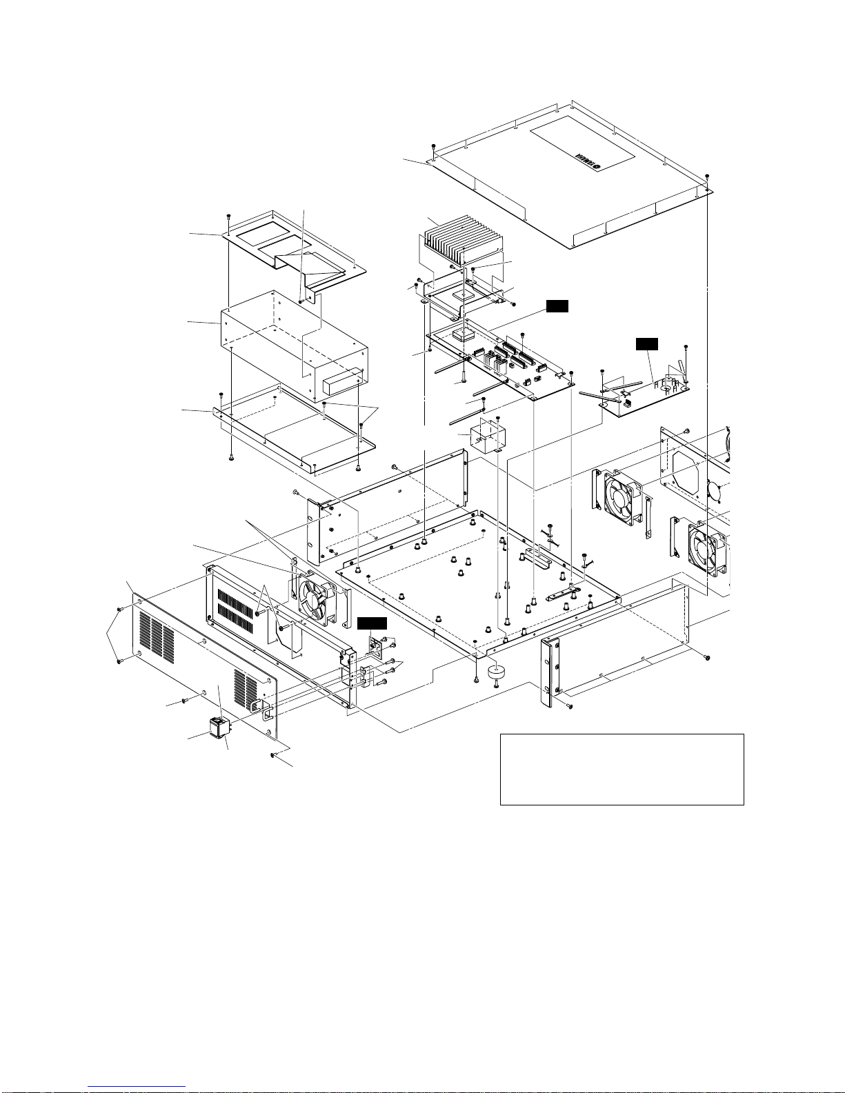
■DISASSEMBLY PROCEDURE
1. Top Cover
(Time required : About 1 minute)
Remove the fourteen (14) screws marked [390]. The
top cover can then be removed. (Fig. 1)
2. Power Supply Unit
(Time required : About 2 minutes)
2-1. Remove the top cover. (See procedure 1)
2-2. Remove the six (6) screws marked [240]. The power
supply unit and the window angle can then be removed.
(Fig. 1)
2-3. Remove the three (3) screws marked [225] and the
screw marked [230A]. The window angle can then be
removed from the power supply unit. (Fig. 1)
2-4. Remove the four (4) screws marked [230B]. The SW
power angle can then be removed from the power
supply unit. (Fig. 1)
3. DC Circuit Board
(Time required : About 2 minutes)
3-1. Remove the top cover. (See procedure 1)
3-2. Remove the eleven (11) screws marked [310].The DC
circuit board can then be removed. (Fig. 1)
3-3. Remove the four (4) screws marked [290] and the
screw marked [300]. The heat sink and holder can then
be removed from the DC circuit board. (Fig. 1)
4. AC Circuit Board
(Time required : About 1 minute)
4-1. Remove the top cover. (See procedure 1)
4-2. Remove the six (6) screws marked [200]. The AC
circuit board can then be removed. (Fig. 1)
5. LED Circuit Board
(Time required : About 1 minute)
5-1. Remove the top cover. (See procedure 1)
5-2. Remove the two (2) screws marked [180]. The LED
circuit board can then be removed. (Fig. 1)
6. PowerTransformer
(Time required : About 1 minute)
6-1. Remove the top cover. (See procedure 1)
6-2. Remove the two (2) screws marked [317]. The power
transformer can then be removed. (Fig. 1)
7. Switch Assembly (Power Switch)
(Time required : About 4 minutes)
7-1. Remove the top cover. (See procedure 1)
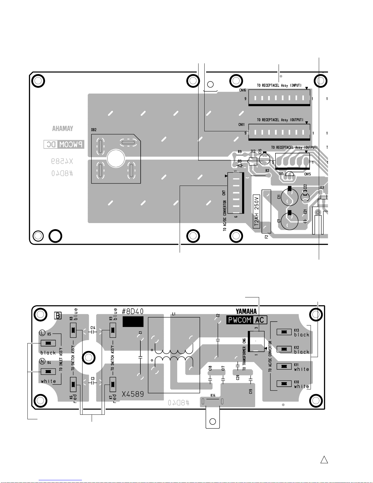
7-2. Remove the connector pins connected to K6 to K9
terminals of the AC circuit board.
7-3. Remove the six (6) screws marked [330] and the four
(4) screws marked [355]. The front panel can then be
removed. (Fig. 1)
7-4. Remove the switch assembly (power switch) by
bending its claw. (Fig. 1)
8. Front Fan Motor
(Time required : About 3 minutes)
8-1. Remove the top cover. (See procedure 1)
8-2. Remove the six (6) screws marked [330] and the four
(4) screws marked [355]. The front panel can then be
removed. (Fig. 1)
8-3. Remove the power switch. (See procedure 7)
8-4. Remove the four (4) screws marked [120A]. The fan
motor (front) and the two (2) fan guides can then be
removed. (Fig. 1)
1. トップカバー(所要時間:約1分)
[390]のネジ14本を外し、トップカバーを外します。
(図1)
2. 電源ユニット(所要時間:約2分)
2-1. トップカバーを外します。(1項参照)
2-2. [240]のネジ6本を外し、電源ユニットとウインドア
ングルを外します。(図1)
2-3. [225]のネジ3本と[230A]のネジ1本を外し、電源ユ
ニットからウインドアングルを外します。(図1)
2-4. [230B]のネジ4本を外し、電源ユニットからSW電源
取付け金具を外します。(図1)
3. DCシート(所要時間:約2分)
3-1. トップカバーを外します。(1項参照)
3-2. [310]のネジ11本を外し、DCシートを外します。
(図1)
3-3. [290]のネジ4本と[300]のネジ1本を外し、DCシート
からヒートシンクDS/ヒートシンク取付金具を外し
ます。(図1)
4. ACシート(所要時間:約1分)
4-1. トップカバーを外します。(1項参照)
4-2. [200]のネジ6本を外し、ACシートを外します。(図1)
5. LEDシート(所要時間:約1分)
5-1. トップカバーを外します。(1項参照)
5-2. [180]のネジ2本を外し、LEDシートを外します。
(図1)
6. 電源トランス(所要時間:約1分)
6-1. トップカバーを外します。(1項参照)
6-2. [317]のネジ2本を外し、電源トランスを外します。
(図1)
7. スイッチAssy(電源スイッチ)
(所要時間:約4分)
7-1. トップカバーを外します。(1項参照)
7-2. ACシートのK6〜K9端子の圧着端子を外します。
7-3. [330]のネジ6本と[355]のネジ4本を外し、フロント
パネルを外します。(図1)
7-4. 電源スイッチのツメを曲げて、スイッチAssy(電源
スイッチ)を外します。(図1)
8. フロントDCファンモーター(所要時間:約3分)
8-1. トップカバーを外します。(1項参照)
8-2. [330]のネジ6本と[355]のネジ4本を外し、フロント
パネルを外します。(図1)
8-3. 電源スイッチを外します。(7項参照)
8-4. [120A]のネジ4本を外し、DCファンモーター(front)
とファンガイド2個を外します。(図1)
(分解手順)