Other manuals for A-450
2
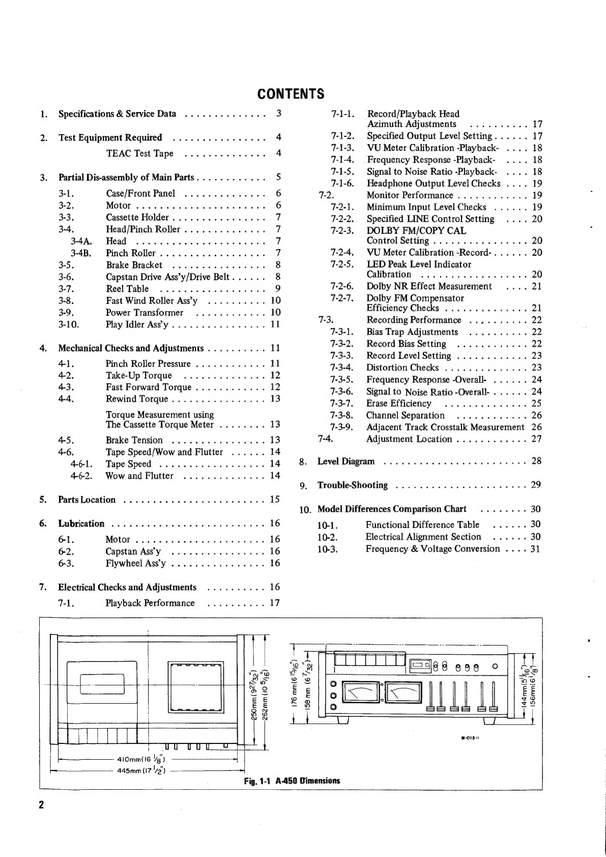
Table of contents
Other Teac Cassette Player manuals
Teac
Teac W-860R User manual
Teac W-600R User manual
Teac Tascam 122 Administrator Guide
Teac A-450 User manual
Teac R-919X User manual
Teac W-550R User manual
Teac V-3000 User manual
Teac W-780R User manual
Teac V-66C User manual
Teac R-H500 User manual
Teac V-970X User manual
Teac V-870 User manual
Teac W-470 User manual
Teac R-H300 User manual
Teac MC-X1R User manual
Teac C-3 User manual
Teac CX-400 User manual
Teac Esoteric R-9000 User manual
Teac V-8000S User manual
Teac V-5010 User manual
Aiwa
Aiwa TP-VS535 operating instructions
Philips
Philips AW 7300 user guide
Philips Video Cassette Recorder instructions
Yamaha
Yamaha MT8X Operation manual
Sherwood
Sherwood Newcastle D-480 operating instructions
Manta
Manta MA408 user manual
GPO
GPO W0162B user guide
Sony
Sony HST-471 Service manual
Sharp
Sharp JC-AV1 Operation manual
Pioneer
Pioneer CT-W103 Service manual
Aiwa HS-JX899 Service manual
Sony TC-K615S operating instructions
Sony CFS-B15 - Am/fm Stereo Cassette Recorder operating instructions
Sony WMFS220 - Portable Sports AM/FM Cassette... operating instructions
Aiwa HS-TA21 operating instructions
Sanyo
Sanyo MCD-ZX700F Service manual
Aiwa CS-P77 Service manual
Sony Pressman TCM-465V operating instructions