THEORY OF OPERAT ION-MAINTENANCE
If you are new to high quality sound recording equip-
ment, you should become aware of the fact that high
quality sound requires high quality maintenance.
Recording studios that rent time by the hour are very
fussy about maintaining their equipment. Tape recorders
and other electronic gear in the studio are checked out
before every session. And, if necessary, adjusted to "spec"
by an "in house" service technician. He is usually
prepared to correct any problem from a minor shift in
circuit performance to
a
major breakdown n amotor. He
has a full stock of spare parts and al1 the est equipment
he needs.
Now that you are running your own "studio" you will
have to make some decisions about maintaining it, and
your 80-8. You will have to become your own "in house"
service technician. Well, what about the test gear and the
spare parts? A stock of spare parts and a super deluxe
electronic test bench can easily cost many times the price
of the recorder. Fortunately. the most frequently needed
adjustments use the least expensive equipment, and the
very costly devices are only needed for major parts
replacements such as drive and rewind motors or head
assemblies. Replacing parts cannot be considered "daily
maintenance" by any means, so we suggest that you leave
the major mechanical and electrical repair to the Dealer
Service Center. That's what it's for
Adjustments to the motors
-
back tension and brake
torque are not required often and can safely be left to
dealer service. The adjustments for wow and flutter
require severa1 thousands of dollars of testgear toperform.
It's not practical to consider doing these adjustments
yourself unless you have fifty machinesto service. Then it
might pay to buy the test gear.
In order to help you make plans about the more routine
adjustments to your 80-8, we have made this maintenance
section of the owners manual as easy to understand as
technology will allow. It's a short course in tape recorder
theory as well as a list of adjustmentsand will help you to
understand what
is
going on inside when you record. Read
the manual, decide what test equipment you can afford
(although it
is
not violently expensive, it
is
not free) and
determine what service you can do yourself.
Cleaning
The first thing-youwill need for service
is
definitely the
least expensive
-
Cleaning fluids and swabs. The whole
outfit,
2
fluids and al1 the cotton swabs you'll need for
months cost less than one roll of high quality tape. We
can't stress the importance of cleaning too much. Clean
up before every session. Clean up after every session.
Clean up every time you take a break in the middle of a
session (we're serious). How come? Well there are two
good reasons we can think of right off the top:
1.
Any dirt or oxide buildup on the heads will force the
tape away from the gaps that record and playback.
This will drastically affect the response. Even so small a
layer of dirt as one thousandth of an inch will cause big
troubles. All the money you have paid for high
performance will be wiped out by abit of oxide. Wipe
itoff with headcleaner and get back to normal.
2.
Tape and tape oxide act very much the same as fine
sandpaper. The combination will grind down the tape
path in time. If you don't clean off this abrasive on a
regular basis, the wear will be much more rapid and,
what's worse, it will become irregular. Even wear on
8
E'
A=
IOMILS
i
O
O.
2
0.4 0.6 O.
8
1.0
SPACING
-
MILS
W
>
0.05
u
J
W
a
0.02
O O
1
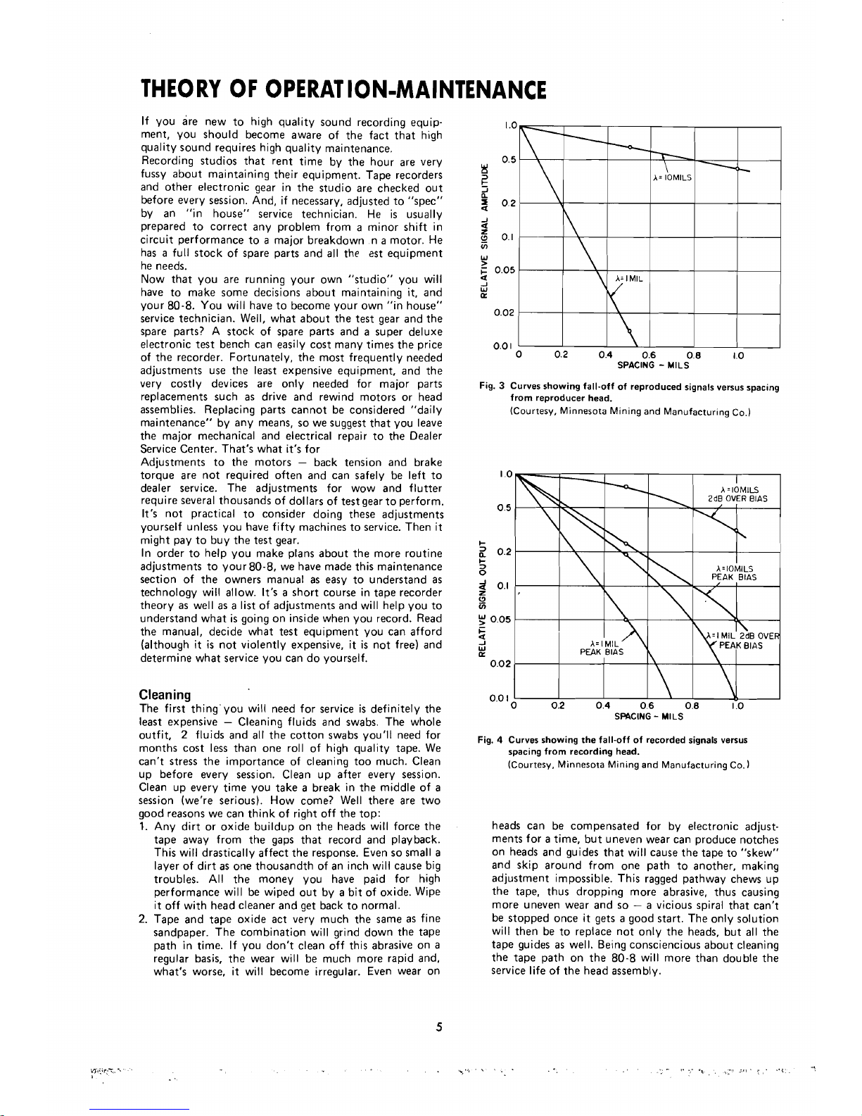
Fig.
3
Curves showing fall-off of reproduced signals versus spacing
from reproducer head.
(Courtesy, Minnesota Mining and Manufacturing Co.)
A-
I
MIL
SPACING
-
MILS
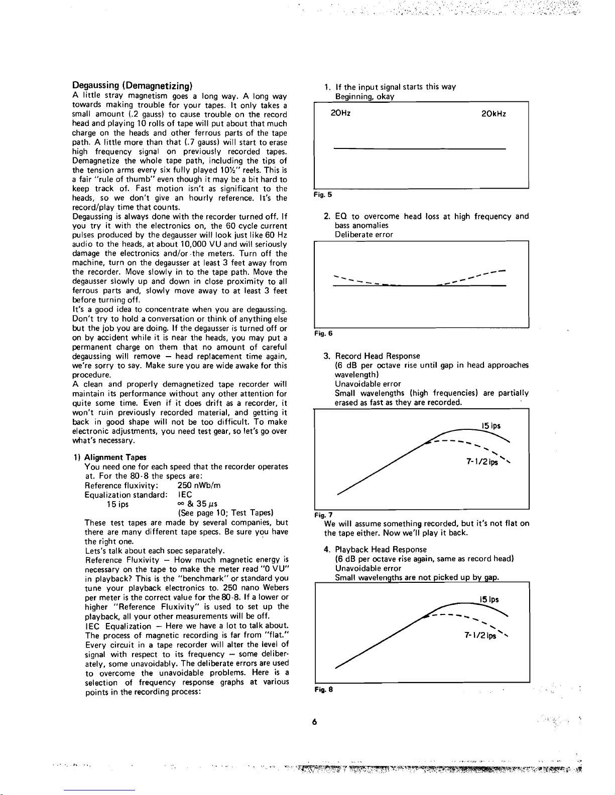
Fig.
4
Curves showing the fall-off of recorded signals versus
spacing from recording head.
(Courtesy, Minnesota Mining and Manufacturing Co.
heads can be compensated for by electronic adjust-
ments for atime, but uneven wear can produce notches
on heads and guides that will cause the tape to "skew"
and skip around from one path to another, making
adjustment impossible. This ragged pathway chews up
the tape, thus dropping more abrasive, thus causing
more uneven wear and so
-
a vicious spira1 that can't
be stopped once it gets agood start. The only solution
will then be to replace not only the heads, but al1 the
tape guides as well. Beingconscienciousabout cleaning
the tape path on the 80-8 will more than double the
service life of the headassembly.