Team Assocciated RC10B6.1 Dirt Light Team Kit User manual


2
:: Introduction
:: RC10B6.1DL KIT Features
:: Additional
:: Other Helpful Items
Thank you for purchasing this Team Associated product. This assembly manual contains instructions and tips for building and
maintaining your new vehicle. Please take a moment to read through the manual and familiarize yourself with the steps.
We are continually changing and improving our designs; therefore, actual parts may appear slightly different than the illustrations.
New parts will be noted on supplementary sheets located in the appropriate parts bags. Check each bag for these sheets before
you start to build.
• Easy access ball differential
• Differential height adjustment with 0, 1, 2, & 3mm insert included
• New slipper assembly for better weight balance and shock clearance
• 3-gear Lay Down Stealth® transmission for lower and more rearward CG
• Heavy-duty V2 routed graphite front shock tower with tower guard
• Heavy-duty V2 routed graphite rear tower, LONG
• Heavy-duty V2 rear axle with 67mm bones
• V2 springs for a more reactive and nimble feel
• Innovative rear arm with molded inserts for ultra-fine lower shock mount adjustment
• Molded spur gear guard to help protect body from damage
• +1 steering block arms optimize feel on dirt tracks
• Battery strap allows the use of optional turnbuckle based braces
• Machined pistons included for better fit and smoother operation
• Aluminum rear clamping hex and front axle with laser etching
• Rear hubs feature large bearings and the easy-insert system to adjust camber link position and rear axle height
• One piece shock bushing to make assembly easier
• Aluminum C and D arm mount included for large range of anti-squat and toe adjustment
• Lightweight aluminum top shaft
• Factory Team upgraded ball bearing kit included (now oiled instead of greased for less drag)
• JConcepts B6 Light weight clear body and wing included
• Cyanoacrylate glue (CA)(#1597)
• Thread locking compound (#1596)
• Tires and Inserts, Fronts and Rears
• Wheels w/12mm Hex
Front Wheels#9690, #9691, #91572, #91573
Rear Wheels #9695, #9696, #91570, #91571
Tools included:
• Allen wrenches 1.5mm, 2.0mm
• #1113 12mm Shock Tool
• Multi-wrench
Associated Electrics, Inc.
26021 Commercentre Dr.
Lake Forest, CA 92630
http://www.RC10.com · http://twitter.com/Team_Associated · http://www.instagram.com/teamassociatedrc/ · http://www.facebook.com/TeamAssociated/
Customer Service
Tel: 949.544.7500
Fax: 949.544.7501
Your new B6.1DL Team Kit comes unassembled
and requires the following items for completion
(refer to catalog section for suggestions):
• R/C two channel surface frequency radio system
• AA-size batteries for transmitter (#302 alkaline)
• Electronic Speed Control, ESC (#27002, 27003, 27004, 27005)
• Steering servo (#27106, #27107)
• R/C electric motor
• Pinion gear (48P), size determined by type/wind of motor
• Battery charger (a peak detection charger, or LiPo compatible charger)
• 2 cell LiPo battery pack (#27318, 27322, 27323, 27324)
• Polycarbonate specific spray paint
• Silicone Shock Fluid (Refer to catalog for complete listings)
• Body Scissors (AE Part # 1737) • FT Body Reamer (#1499) • Shock Pliers (#1675)
• FT Hex/Nut Wrenches (AE Part # 1519) • FT Ballcup Wrench (#1579) • FT Universal Tire Balancer (#1498)
• Green Slime shock lube (AE Part # 1105) • FT Dual Turnbuckle Wrench (#1114) • Calipers or a Precision Ruler
• Soldering Iron • Hobby Knife • Wire Cutters
• Needle Nose Pliers
3
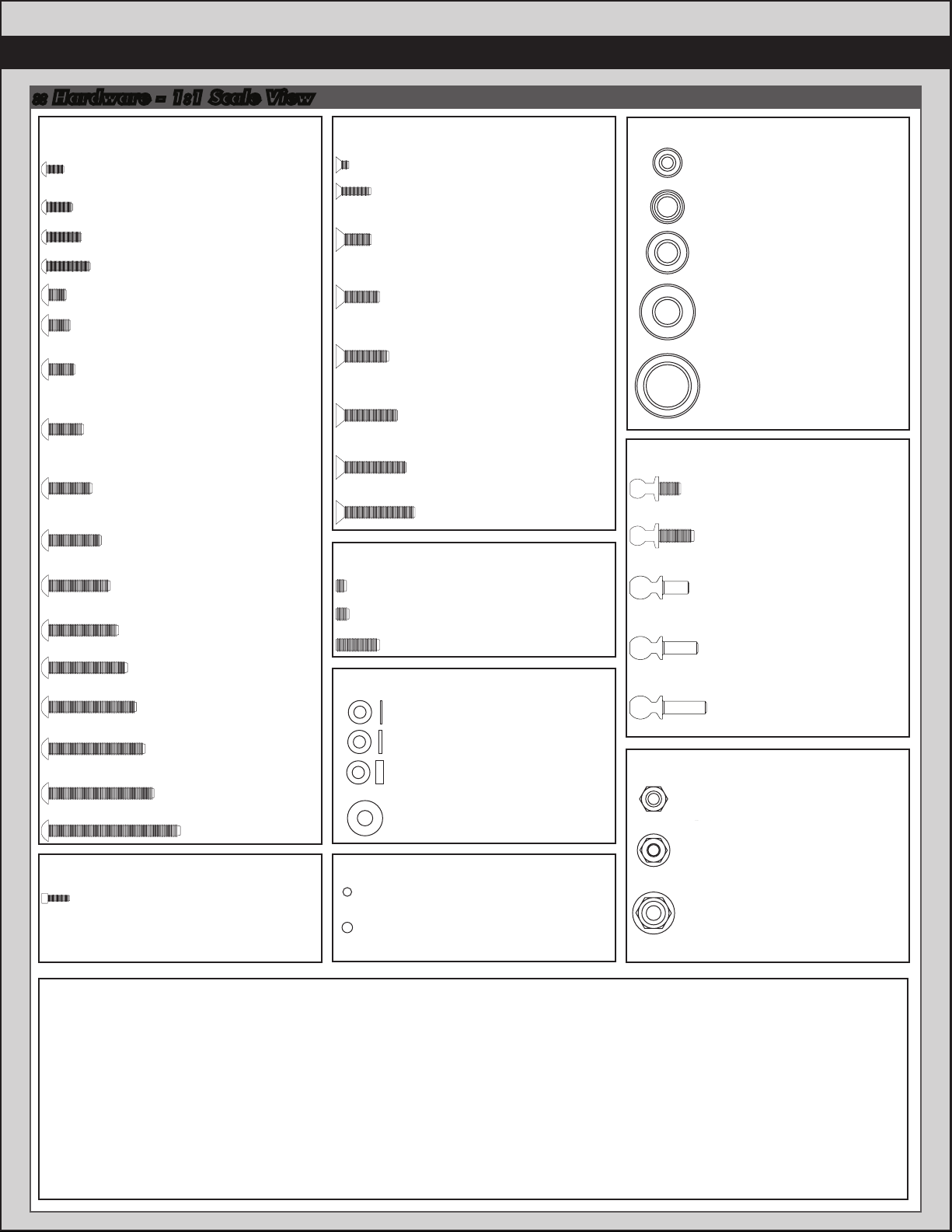
:: Hardware - 1:1 Scale View
2x3mm (91743)
2.5x8mm (31448)
3x8mm (25201)
Aluminum (8553)
Titanium (91592)
3x10mm (25202)
Aluminum (8555)
Titanium (91593)
3x12mm (25203)
Aluminum (8556)
Titanium (91594)
3x14mm (89208)
Aluminum (8567)
Titanium (91595)
3x16mm (25204)
Titanium (91596)
3x18mm (89209)
Titanium (91597)
Flat Head (fhcs)
2x4mm (31510)
Aluminum (8545)
2.5x6mm (31520)
2.5x8mm (31521)
2.5x10mm (31522)
3x4mm (91158)
3x5mm (31530)
3x6mm (31531)
Aluminum (8550)
Titanium (91580)
3x8mm (31532)
Aluminum (8552)
Titanium (91581)
3x10mm (25211)
Aluminum (8554)
Titanium (91582)
3x12mm (89202)
Titanium (91583)
3x14mm (25187)
Titanium (91584)
3x16mm (89203)
Titanium (91585)
3x18mm (2308)
3x20mm (25188)
Titanium (91587)
3x22mm (25189)
Titanium (91588)
3x24mm (89204)
Titanium (91589)
3x30mm (91478)
Button Head (bhcs) Ball Bearings
3x7x3mm (91475)
5x8x2.5mm (31400)
5x10x4mm (91560)
6x13x5 (91562)
10x15x4 (91563)
3x2.5mm (31500)
3x3mm (25225)
3x10mm (4671)
Set Screws
5.5x0.5mm (31381)
5.5x1.0mm (31382)
5.5x2.0mm (31383)
3x8mm Washer (89218)
Shims and Washers
Notes:
5/64 Diff Thrust Balls (6574)
3/32 Carbide Diff Balls (6581)
3/32 Ceramic Diff Balls (6584)
Diff Balls
M3 Nut (91477)
M3 Alum. Locknut, Blue (31550)
M3 Locknut, Black (25215
M3 Locknut w/Flange (25612)
FT 3mm Locknuts, Blue(25392)
M4 Locknuts:
Serrated Steel (Silver)(91826)
Flanged (Black) (91148)
FT Aluminum (Blue) (31551)
Serrated Aluminum (Black) (91738)
Nuts (lock/plain)
Cap Head (shcs)
1.6 x 5mm (91611)
Ballstuds
Silver 5mm long (31283)
Ti Nitride 5mm long (31291)
Silver 8mm long (31284)
Ti Nitride 8mm long (31292)
HD 6mm (91047)
Ti Nitride HD 6mm (91118)
Ti HD 6mm (91751)
HD 8mm (91048)
Ti Nitride HD 8mm (91119)
Ti HD 8mm (91752)
HD 10mm (91049)
Ti Nitride HD 10mm (91120)
Ti HD 10mm (91753)
4
:: Table of Contents
:: Notes
This symbol indicates a special
note or instruction in the manual.
This symbol indicates a Racers Tip.
1................... Cover
2................... Introduction
3...................1:1 Hardware “Fold Out”
4................... Table of Contents
5....................Bag 1
5 - 8..............Bag 2
8 - 9..............Bag 3
9 - 10...........Bag 4
10 - 11.........Bag 5
11 - 13........Bag 6
13 - 14........Bag 7
14 - 15........Bag 8
15 - 16........Bag 9
17 - 19........Bag 10
19 - 21....... Tuning Tips
22 - 30.......Catalog
31................ Notes / Contact Info
32................Setup Sheet “Kit Setup”
33................Setup Sheet “Blank”
34................Back Cover
!There is a 1:1 hardware foldout page in the
front of the manual. To check the size of a part,
line up your hardware with the correct drawing
until you find the exact size. Each part in the
foldout has a number assigned to it for ordering
replacement parts.
Associated Electrics, Inc.
26021 Commercentre Dr.
Lake Forest, CA 92630
http://www.RC10.com · http://twitter.com/Team_Associated · http://www.instagram.com/teamassociatedrc/ · http://www.facebook.com/TeamAssociated/
Customer Service
Tel: 949.544.7500
Fax: 949.544.7501
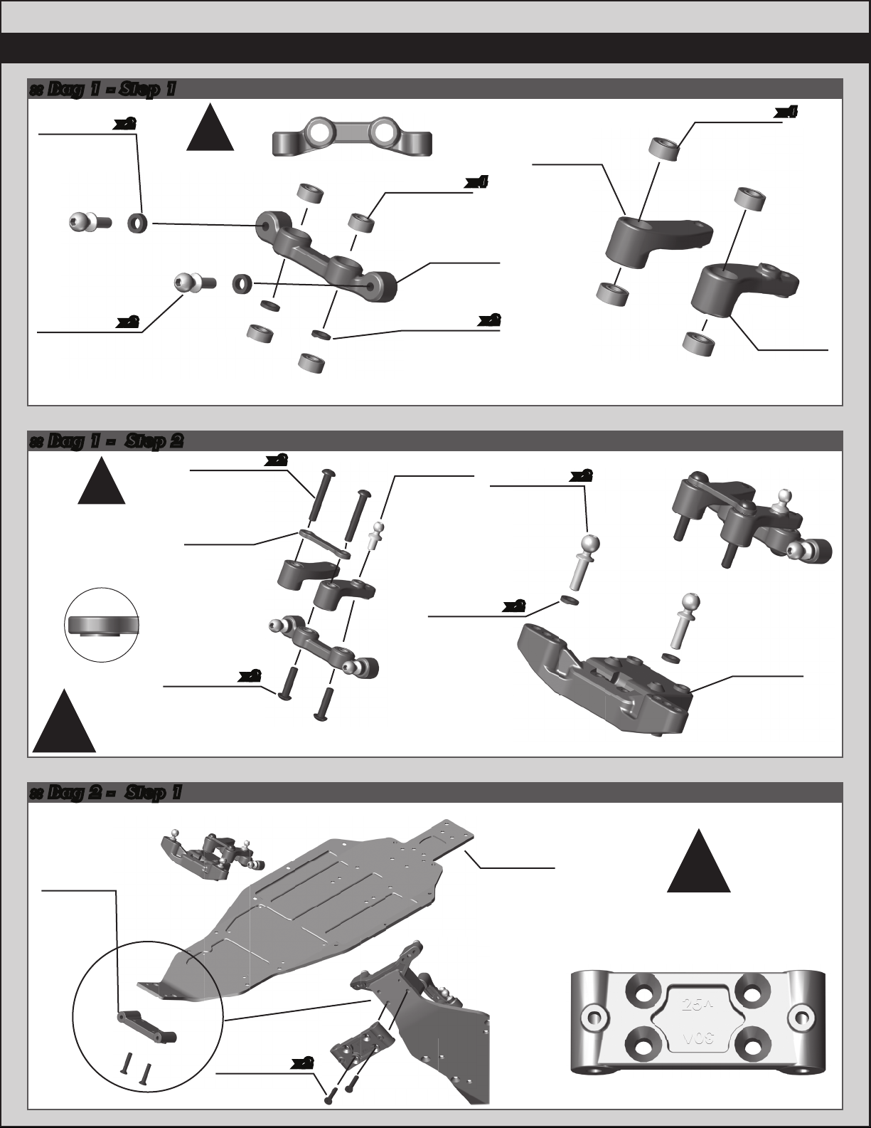
:: Bag 1 - Step 2
:: Bag 2 - Step 1
5
:: Bag 1 - Step 1
4/19
91667
Steering
Bellcrank
Brace
x2
91678
M3 x 20mm
BHCS
Shouldered
Do not overtighten steering bolts. Make sure
there is free movement in the steering rack.
91475
3 x 7 x 3
Ball Bearing
91475
3 x 7 x 3
Ball Bearing
91667
Steering
Rack
91667
Steering
Bellcrank
(Right)
Front
91667
Steering
Bellcrank
(Left)
x4
x4
x2
x2
x2
91048
Heavy-duty
Ballstud,
8mm
31382
FT Ballstud
Washer,
Aluminum
(1mm)
31382
FT Ballstud
Washer,
Aluminum
(1mm)
!
x2
89202
M3 x 12mm
BHCS
31283
5mm Ball
Stud, Long
Note orientation
of steering rack.
!
The steering
bellcrank brace
has offsets on one
side. They should be
installed towards
the bearings.
!x2
x2
91049
Heavy-duty
Ballstud,
10mm
31382
FT Ballstud
Washer,
Aluminum
(1mm) 91766
Front
Ball Stud
Mount
x2
25204
M3 x 16mm
FHCS
91656
Bulkhead
91765
Chassis,
B6.1 There are two bulkhead settings
(25 °, 30 °). 25 °is the standard used.
The arrow should point
forward for the desired setting.
!
25
30
>
>
TOP
6
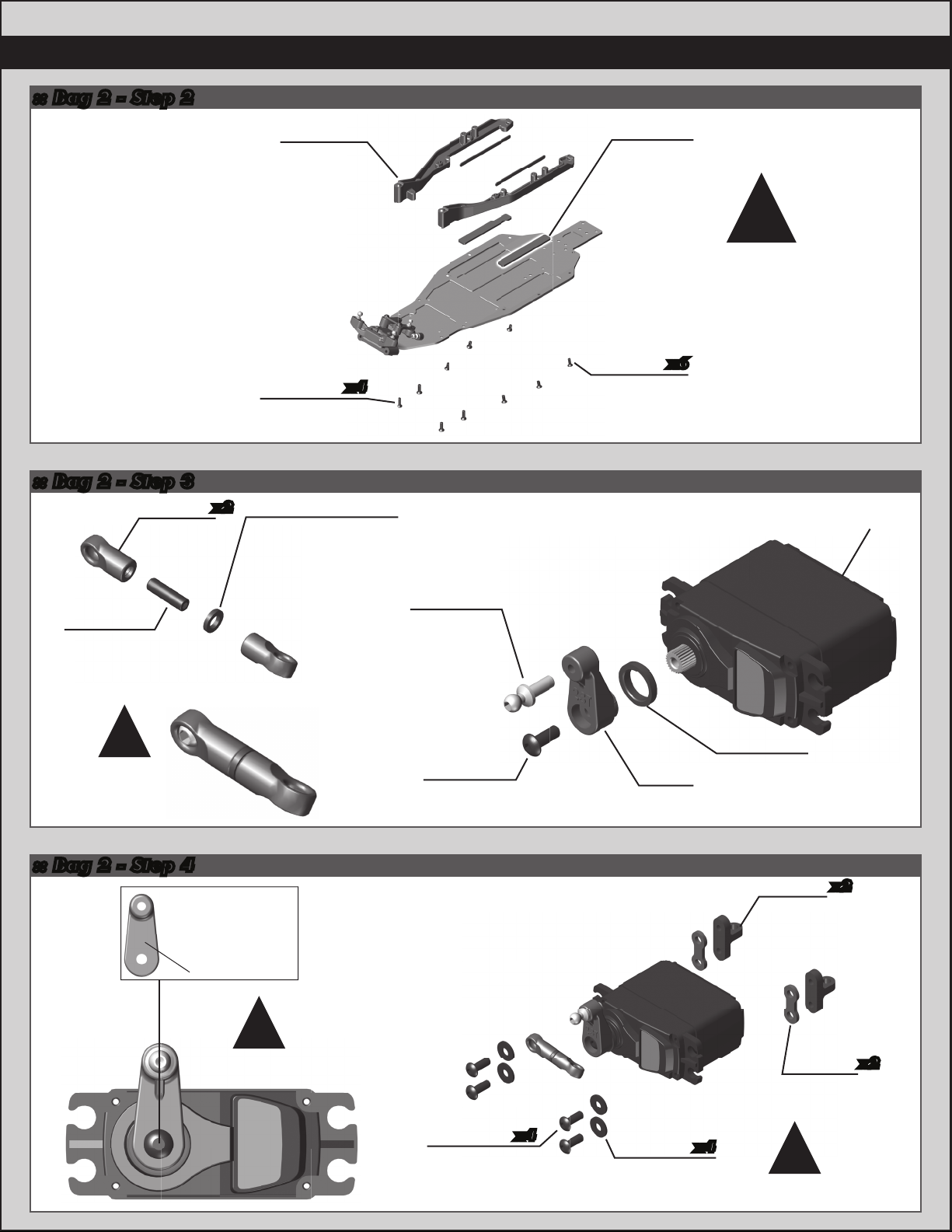
:: Bag 2 - Step 2
:: Bag 2 - Step 4
A - Airtronics
F - Futaba
H - Hitec
J - JR
Printed here
:: Bag 2 - Step 3
4671
M3x10mm
Set Screw
91820
Steering
Link, B6.1
31382
FT Ballstud
Washer, aluminum
(1mm)
Tighten the
steering link ball
cups all the way
until snug.
!
Align the servo
horn 90 degrees
!
91728
Servo Horn
Ring
31284
8mm Ball
Stud, Long
91728
Servo
Horn
Servo not
included!
x2
31532
M3 x 8mm
BHCS
x4
x6
25202
M3 x 10mm
FHCS
91652
Side Rails
(L & R)
25201
M3 x 8mm
FHCS
91734
Battery
Foam, B6
#91734 - Battery Foam
There are two thickness
options to accomodate
any battery size.
!
#91728 - Servo Spacers
are not required for all servos.
!
89218
M3 x 8mm
Washer
91719
Servo
Mount
91728
Servo
Spacers
31532
M3 x 8mm
BHCS
x4
x2
x2
x4

7
:: Bag 2 - Step 7
:: Bag 2 - Step 6
:: Bag 2 - Step 5
The front hinge pin
brace has a sharp
edged side, and a
rounded edge side.
Mount the sharp
edge side towards
the bulkhead.
!
25211
M3 x 10mm
BHCS
x2
91766
Top Plate,
B6
25187
M3 x 14mm
BHCS
x2
25211
M3 x 10mm
BHCS
x2
31510
M2 x 4mm
BHCS
91673
Front Arms,
Gull-Wing, B6
91656
Front Hinge
Pin Brace,
B6
x2
x2
91670
Hinge Pin
(front, Inner)
25225
M3 x 3mm
Set Screw
x2
x2 25204
M3 x 16mm
FHCS
91685
Front
Bumper
x2

:: Bag 3 - Step 2
:: Bag 3 - Step 1
8
:: Bag 2 - Step 8
Build 2 (1 left, 1 right)
x2
31531
M3 x 6mm
BHCS
91560
5 x 10 x 4
Bearing
91682
Front Axle
91677
Steering
Block
(4mm)
#1596
thread lock
25188
M3 x 20mm
BHCS
25202
M3 x 10mm
FHCS
91815
Shock
Bushing,
10mm
91768
Front Shock
Tower,
Gull-Wing
91771
Front Shock
Tower Cover,
Gull-Wing
x2
x4
x2
Build 2 (1 left, 1 right)
91049
Heavy-duty
Ballstud,
10mm
25215
M3 Locknut,
black
91675
Caster
Block Insert
(+5°)
There are three caster
block inserts included
(0°, +/- 2.5 °, +/- 5 °).
+5 ° is the standard
insert used.
Tab up =positive caster
Tab down =negative caster
There are two sets of steering
blocks included with your kit, a 3mm
and a 4mm. The 4mm steering
blocks are used for the kit setup.
!
!
91675
Caster
Block
You can install an
optional #31520 screw
to use as a steering
stop setting.
You can install an
optional #4670 set
screw to better hold
the caster block inserts
and hinge pin.
Total
Caster
25°25°30°20°2 7. 5 °22.5°
0 2.5 up 5 up2.5 down 5 down
30°30°35°25°32.5°2 7. 5 °
Bulkhead
Orientation
Caster Block Insert
Bearing
Bearing
There are two sets of steering
There are two sets of steering
blocks included with your kit, a 3mm
blocks included with your kit, a 3mm
and a 4mm. The 4mm steering
and a 4mm. The 4mm steering
4L
25215
M3 Locknut,
black
91680
Steering
Block Arm
(+1)
91048
Heavy-duty
Ballstud,
8mm
31382
FT Ballstud
Washer,
Aluminum
(1mm)
optional #31520 screw
31532
M3 x 8mm
BHCS
x2
25202
M3 x 10mm
FHCS
x4x4

:: Bag 4 - Step 2
:: Bag 4 - Step 1
9
:: Bag 3 - Step 3
Build 2 (1 left, 1 right) Build 2 (1 left, 1 right)
91777
Rear
Arms (L&R)
91777
Rear Arm
Threaded
Insert
x2
x2
91685
Rear
Bumper
91688
Aluminum
Arm Mount, D
91670
Hinge Pin
(rear, Inner)
92014
Arm Mount
Inserts
(up, 0.5°)
x2
x2
25187
M3 x 14mm
BHCS 91676
Caster Hat
Bushing
Top: 2mm
Bottom: 1mm
x2
31510
M2 x 4mm
BHCS
91675
Caster Block
Spacer
91670
Hinge Pin
(front, Outer)
x2
91772
Aluminum
Arm Mount,
C
92014
Arm Mount
Inserts
(up, 0.5°)
x2
31541
M3 x 6mm
FHCS
x2
#91670 - Hinge Pin will be
tight in the caster blocks,
but should rotate freely
in the front arms.
!
BCD A
Install the rear arm threaded
insert in the same position for
the left and right side arms!
See page 10 for
pill chart tips
!
!
Center 0.5° Up
Center 0.5° Up

10
:: Bag 5 - Step 2
:: Bag 5 - Step 1
:: Bag 4 - Step 3
#6588
black grease
6573
Diff thrust
washer
6574
5/64 diff
thrust
balls
6573
Diff thrust
bolt
x2
x6
31400
5 x 8 x 2.5mm,
Bearing
x2
6581
3/32 carbide
diff balls
91419
Diff Gear,
52T
91701
Ball Diff
Outdrive
91701
Ball Diff
Outdrive
7666
Diff Drive
Ring
7666
Diff Drive
Ring
x14
#6591
diff lube
#6591
diff lube
#6591
diff lube
Anti-SquatToe-In
3°
Kit Setup
1°
Kit Setup
3° 2°
3° 1°
The (#91772) C and (#91688) D aluminum arm
mounts allow for a large amount of setup
combinations when using the (#92014) 0.5°
and 1°arm mount inserts.
For a complete list of pill setup combinations, please
visit our website by using the link or QR code below.
https://www.teamassociated.com/pdf/cars_and_
trucks/RC10B6/B6_B6D_Pill-Chart.pdf
!D Plate
Center 0.5° Up
C Plate
Center 0.5° Up
D Plate
Center
C Plate
Center
D Plate
Center
C Plate
1° Up
Commonly used setups
11
:: Bag 6 - Step 2
:: Bag 6 - Step 1
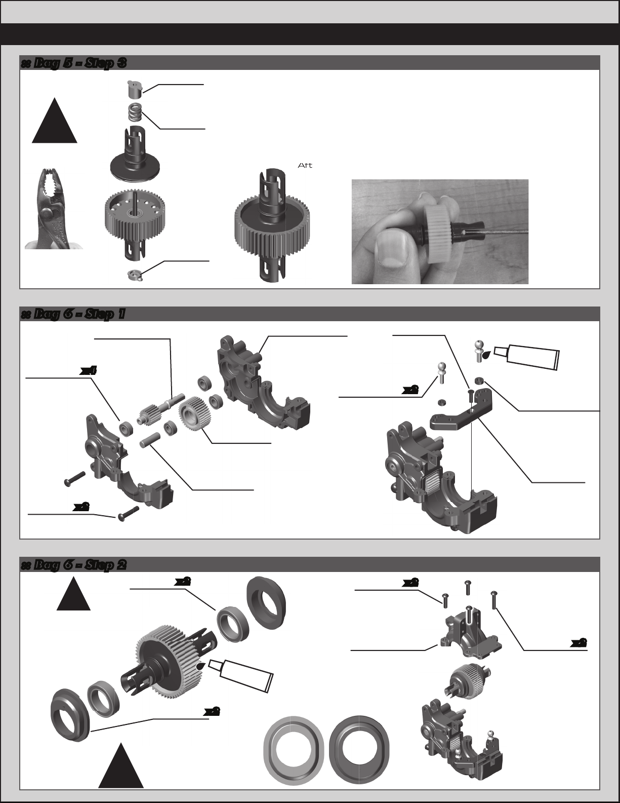
:: Bag 5 - Step 3
As you tighten the diff bolt, you will notice the T-nut ears moving
closer to the bottom of the outdrive slot. This compresses the
spring behind the T-nut. The spring should be completely
compressed at the time the T-nut reaches the end of the slot.
Caution! Pay close attention to the feeling when the spring is
completely compressed. Do not overtighten the bolt. When you
feel the spring completely compressed, loosen the diff bolt 1/8”
of a turn. Your diff should now operate smoothly but with
resistance as the outdrives move in opposite directions.
After you have driven the car once, re-check the diff setting.
After you have driven the car once, re-check the diff setting.
6575
Diff
cover
6575
Locking
t-nut
6582
Diff
thrust
spring
Compress
spring first.
!
#6591
diff lube
Add a drop of Diff
Lube (#6591) to
the teeth of the diff
gear, idler gear, and
top shaft.
!
91792
B6.1 Diff
Height Insert
91563
10x15x4
Bearing
x2
x2
!
2
1
3
0
Diff Height Inserts:
The number on top
is the setting.
Stock diff height is 0.
91791
B6.1 Laydown
Gearbox
(right & left)
91560
5 x 10 x 4,
Bearing
89203
3x16mm
BHCS
31448
2.5x8mm
FHCS
91716
Idler Gear
39T
91799
B6.1 Laydown
Top Shaft
91132
Idler Gear
Shaft,
Aluminum
x4
x2
91048
Heavy-duty
Ballstud, 8mm
x2
91775
B6.1 Rear
Ballstud
Mount,
Aluminum
31383
Ballstud
Washers,
5.5x2.0mm,
Blue Aluminum
89202
3 x 12mm
BHCS
91791
B6.1 Laydown
Gearbox Top
89203
3 x 16mm
BHCS
x2
x2
#1596
thread lock

12
:: Bag 6 - Step 5
:: Bag 6 - Step 4
:: Bag 6 - Step 3
91811
B6.1 Spur
Gear, 78T
91799
B6.1 Top
Shaft Screw
91799
B6.1 Top
Shaft Pin
x2
9611
Slipper
Pad, V2
91803
B6.1 Slipper
Hub, Inner
91804
B6.1 Slipper
Hub, Outer
25202
M3 x 10mm
FHCS
x6
Set nut
flush with
top shaft.
See page 20 for gear
mesh, and slipper clutch
setting instructions!
!
!
25204
M3 x 16mm
FHCS
x2
91801
Slipper Spring
Adapter, Inner
91801
Slipper Spring
Adapter, Inner
91801
Slipper
Spring
25215
M3
Locknut
!
#91811 spur gear
walls should point
away from gear box.
25202
3 x 10mm
FHCS
91813
B6.1 Gear
Guard 91795
B6.1 Laydown
Motor Plate
x3
91819
B6.1 Shock
Pivot Ball
91709
Lay-Down
Chassis
Brace
89203
3 x 16mm
BHCS
25188
3 x 20mm
BHCS
There’s also a
72T, 48P spur
gear (#91809)
included for
stock motor use!
!
13
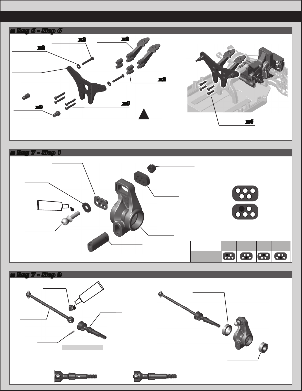
:: Bag 7 - Step 2
:: Bag 7 - Step 1
:: Bag 6 - Step 6
Build x2 (right and left side)
Rear Hub Link Setting
(Right Side Shown):
(Right Side Shown):
Up A
E
C
C
E
A
B
D
D
B
Down
Insert 0/3 up
0 (low) + 3mm + 1mm + 2mm
1/2 up0/3 down 1/2 down
Recommended
Ballstud location
Axle Height
Build x2 (right and left side)
25189
M3 x 22mm
BHCS
x2 x2
x2
91718
Rear Wing
Mount
91718
Rear Wing
Mount Spacer
25188
M3 x 20mm
BHCS
89218
M3 x 8mm
Washer
91816
Shock
Bushing,
12mm
91770
Rear Shock
Tower, B6.1
(Long)
x4
x2
x2
#1596
thread lock
25215
M3 Locknut,
black
91698
Rear Hub
Link Nut
91779
Rear Hub
Link Insert
91779
Rear Hub
B6.1
91049
Heavy-duty
Ballstud,
10mm
89218
3 x 8mm
Washer
91563
10 x 15 x 4
Bearing
91562
6 x 13 x 5
Bearing
There is an optional wing mount spacer included
in your kit. If you do not use the optional wing
mount spacer, use #89202 3 x 12mm BHCS
instead of the #25188 3x20mm BHCS.
!
91762
HD CVA
Axle, V2
91438
CVA Pin
#6588
black grease
91438
CVA
Coupler
91434
CVA Bone,
67mm
CVA Axle Holes
There are two hole locations on the #91762 CVA axle.
One is used for the included 67mm CVA bones, and
one for the optional 65mm CVA bones.
Use the inner hole for the included 67mm CVA bones.
67mm hole
location
65mm hole
location
91779
Rear Hub
Insert (0/3)
Kit Setup: Tab up (0mm)
89202
M3 x 12mm
BHCS
x4
14
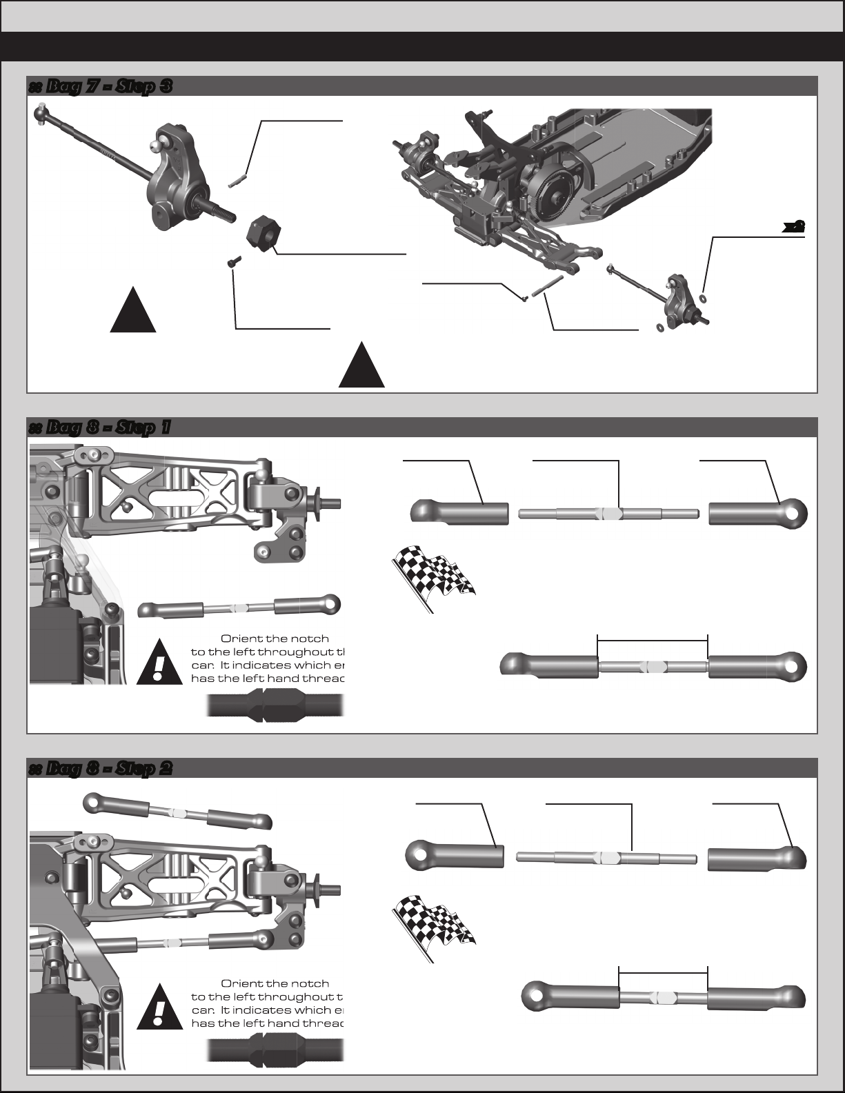
:: Bag 8 - Step 2
:: Bag 8 - Step 1
:: Bag 7 - Step 3
91722
Ball Cup
91722
Ball Cup
91723
Turnbuckle
3x48mm
Racers Tip:
Use black grease
(#6588) on the
threads of the
turnbuckles for
easier ball cup
installation!
Orient the notch
to the left throughout the
car. It indicates which end
has the left hand threads!
!
Build x2 (right and left side)
Front Camber Turnbuckle
23.00mm
91722
Ball Cup
91722
Ball Cup
91723
Turnbuckle
3x48mm
28.50mm
Steering Turnbuckle
Build x2 (right and left side)
Racers Tip:
Use black grease
(#6588) on the
threads of the
turnbuckles for
easier ball cup
installation!
Orient the notch
to the left throughout the
car. It indicates which end
has the left hand threads!
!
Build x2 (right and left side)Build x2 (right and left side)
Orient the notch
to the left throughout the
car. It indicates which end
has the left hand threads!
!
Orient the notch
to the left throughout the
car. It indicates which end
has the left hand threads!
!
91779
Rear Hub
Spacer
91670
Hinge Pin
(rear, outer)
31510
M2 x 4mm
BHCS
x2
91611
M1.6 x 5mm
SHCS
91436
CVA Wheel
Hex Pin
91610
Clamping Wheel
Hex, 7mm Offset
(rear)
Do not overtighten the
1.6 x 5mm SHCS into the
Clamping wheel hex.
!
#91670 - Hinge Pin will be
tight in the rear hub, but
should rotate freely
in the rear arms.
!
15
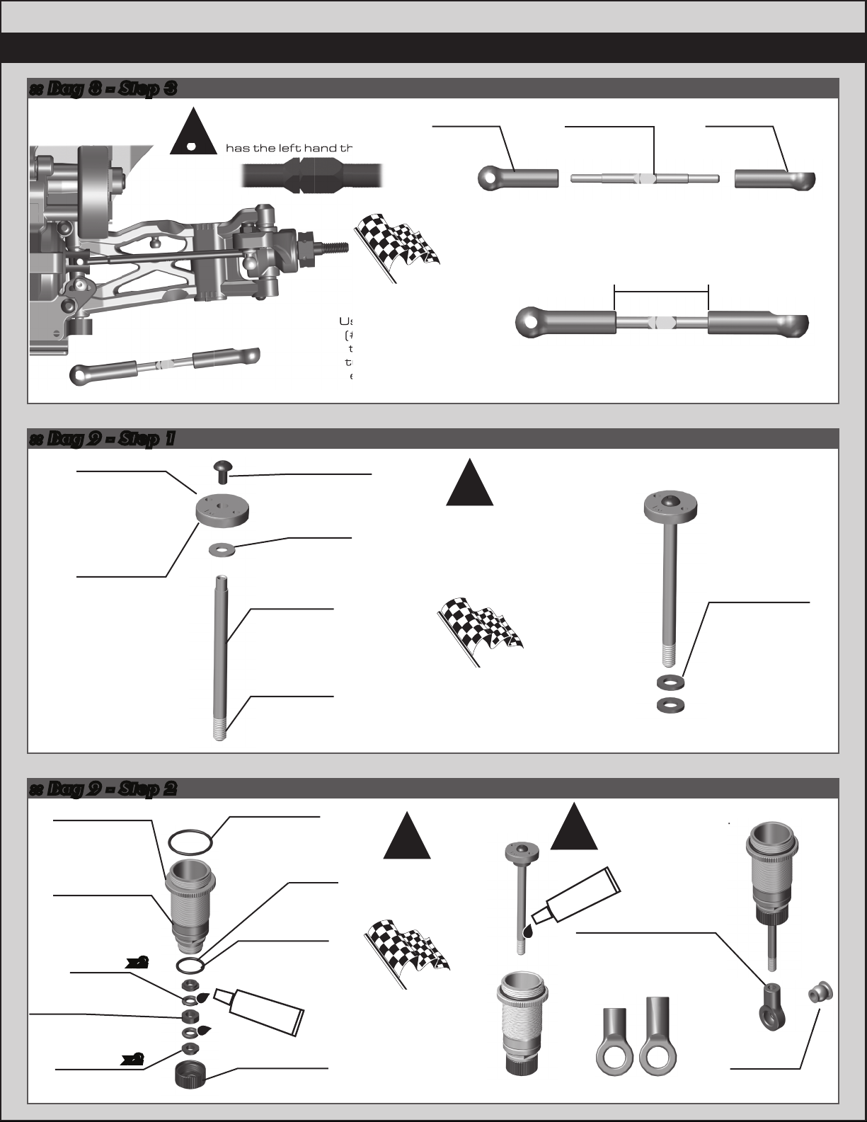
:: Bag 9 - Step 2
:: Bag 9 - Step 1
4187
Nylon Spacer,
(.030)
Front:
2 spacers
Rear:
1 spacers
:: Bag 8 - Step 3
Racers Tip:
Use a marker over the
numbers on the pistons to
make them easily visible!
Mount the shock
pistons with the
number facing up!
!
91722
Ball Cup
91722
Ball Cup
91723
Turnbuckle
3x48mm
Racers Tip:
Use black grease
(#6588) on the
threads of the
turnbuckles for
easier ball cup
installation!
Orient the notch
to the left throughout the
car. It indicates which end
has the left hand threads!
!
Build x2 (right and left side)
Rear Camber Turnbuckle
23.75mm
Use black grease
(#6588) on the
threads of the
turnbuckles for
easier ball cup
has the left hand threads!
!
91480
12x23mm V2
Shock Bodies
(front)
91482
12x31mm
V2 Shock
Bodies (rear)
91495
V2 Shock
Hat Bushing
91495
V2 Shock
Spacer
91493
X-Ring
31327
VCS3 Shock
Bottom Cap
31327
VCS3 Shock
Bottom Cap
O-Ring
91491
12mm
Shock Cap
O-Ring
x2
x2
#1105
green slime
Lightly rub shock oil
on the o-ring before
installation!
There is a short and
long shock eyelet.
Front and rear
shocks use the
long eyelet.
Racers Tip:
Coating the o-rings
with green slime
(#1105) helps seal
& reduce o-ring
swell! Green slime
not included in kit!
!!
long shock eyelet.
#1105
green slime
91820
Shock Eyelet
Front Shocks - Long
Rear Shocks - Short
91819
Shock
Pivot Ball
Short / Long
91626
FT 12mm V2
Shock Piston,
2x1.6 flat
(front)
91627
FT 12mm V2
Shock Piston,
2x1.7 flat
(rear)
91615
V2 3 x 21
Shock Shaft
TiN (front)
31510
M2 x 4mm
BHCS
89278
2.5mm
Washer
91619
V2 3 x 27.5
Shock Shaft
TiN (rear)

16
:: Bag 9 - Step 5
:: Bag 9 - Step 4
:: Bag 9 - Step 3
Front Shock: 30 wt
#5422
Rear Shock: 30 wt
#5422
Shock fluid
Steps 9-10Step 8Steps 6-7Steps 4-5Steps 2-3
Shock Bleeding Steps:
1. Before assembly, get each bleed
screw and thread it 1-2 turns into
the shock cap, then remove the
screw. This will make it easier when
you are bleeding your shocks.
2. Pull shock shaft down.
3. Fill shock body 3/4 full with silicone
shock fluid.
4. Slowly move the shock shaft up and
down to remove air from under the
piston.
5. Wait for bubbles to come to surface.
6. Fill shock body to top with silicone
shock fluid.
7. Place a drop of oil in the cap and on
cap threads.
8. Install cap (without bleed screw) and
tighten completely.
9. Slowly compress shaft all the way to
bleed excess silicone shock fluid out
the hole in the cap (use rag around
shock to catch excess fluid).
10. Install M2x4mm button head
screw until snug while shaft is fully
compressed.
Rear Shock: 30 wt
91492
M2 x 4mm
BHCS
91814
12mm
Shock Cap
Stroke
Front: 20.5mm
Rear: 28mm
Stroke
Stroke
Shock fluid
91304
12mm
Threaded
Collar
91304
12mm
Threaded
Collar
O-ring
x4
x4
Threaded
91814
12mm shock
spring cup
(Front - 5mm
Rear - 5mm)
91831
12mm Front
Spring, White
(3.40lb)
91838
12mm Rear
Spring, White
(1.91lb)
Front:
3.00mm
Rear:
9.00mm
Build x2 front and x2 rear shocks
Racers Tip:
Use your finger to rub
shock oil on the o-ring for
smoother adjustment!
#91310 12mm Shock Spring Cups
0mm 5mm 9mm
Use outside
hole in
front arm!
!
25612
M3 Locknut
w/Flange
25612
M3 Locknut
w/Flange
25187
M3 x 14mm
BHCS
25188
M3 x 20mm
BHCS
Build x2 (right and left side)Build x2 (right and left side)
Make sure the
flange on the
shock pivot ball is
towards the rear
arm.
!
17
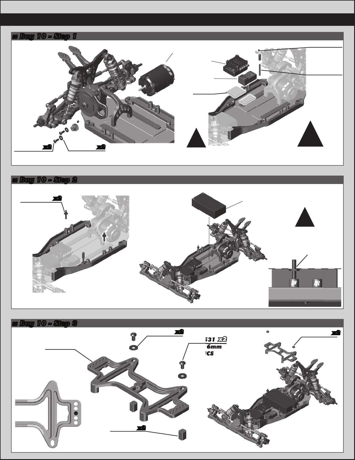
:: Bag 10 - Step 3
:: Bag 10 - Step 2
:: Bag 10 - Step 1
Make sure the
battery strap
shoulder screw is
flush with the top of
your battery pack!
!
RF
Battery
not included!
1
2
3
4
5
Front
31531
M3 x 6mm
BHCS
89218
3 x 8mm
Washer
x2
x2
x2
91731
Battery
Strap, B6
91731
Battery
Strap Nut,
B6
See page 20 for
gear mesh setting
instructions!
!
Motor not included!
Pinion / Setscrew
not included!
31532
M3 x 8mm
BHCS
x2
x2 89218
3 x 8mm
Washer
ESC not
included!
6727
Servo
Tape
There are two options
for mounting your
antenna.
!
Receiver not
included!
25225
M3 x 3mm
Set Screw
6338
Antenna
Tube & Cap
91730
Battery Strap
Shoulder
Screw
x2
31531
M3 x 6mm
BHCS
x2
x2
91729
Thumb
Screw, B6
x2

18
:: Bag 10 - Step 4
91718
Wing
Button
91741
Wing,
B6
91718
Wing
Mount
25202
M3 x 10mm
FHCS x2
x2
Mount
Mount
Pic 1: Pic 2: Pic 3:
Cut Line B
Cut Line A
Cut Line B
Cut Line A
Body Trimming / Mounting:
There are 3 body trimming options depending on what transmission and
shock position you choose to run.
Laydown (Pic 1): Laydown Transmission.
• Cut Line A is for shocks mounted in front of arm.
• Cut line B is for shocks mounted in rear of arm.
Layback (Pic 2): Layback Transmission.
• Cut Line A is for shocks mounted in front of arm.
• Cut line B is for shocks mounted in rear of arm.
Standup (Pic 3): 3 Gear Stand Up Transmission.
Front of Vehicle
0° - Mount under wing
3° - Mount on top of wing
6° - Mount under wing - KIT
Wing Mount
19
:: Tuning Tips
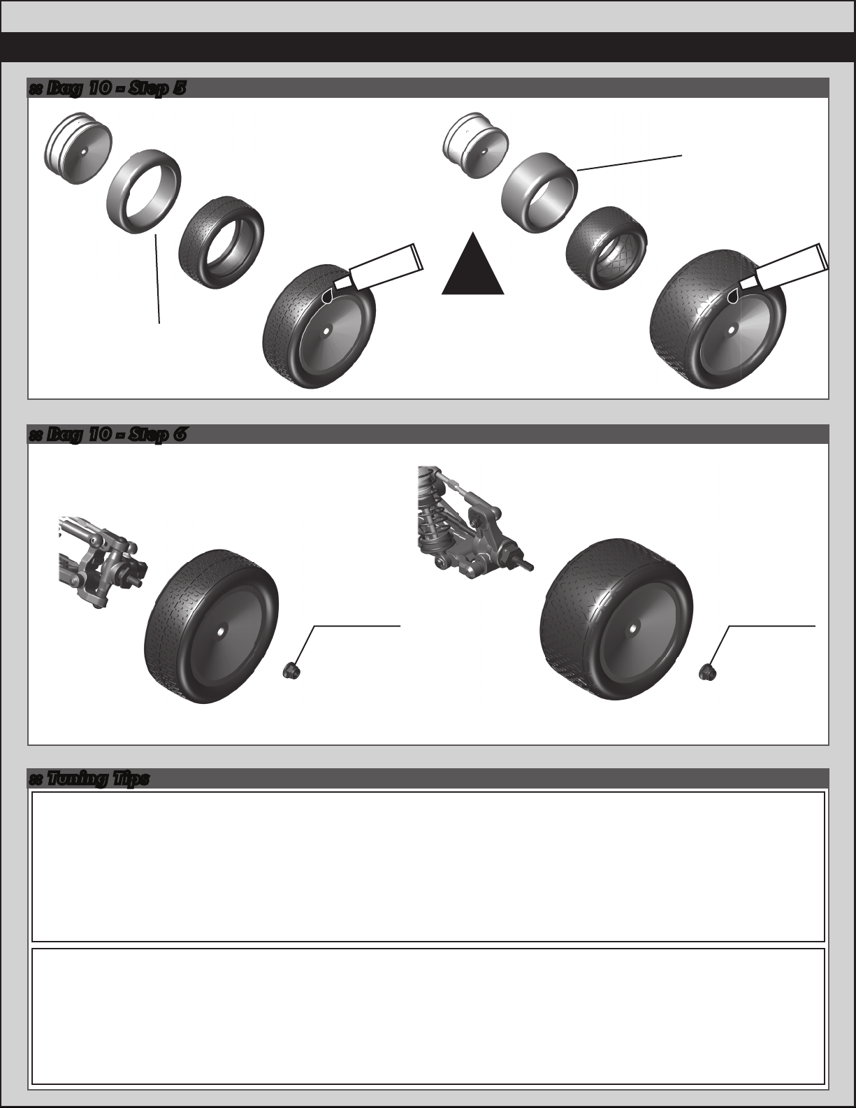
:: Bag 10 - Step 5
:: Bag 10 - Step 6
Tips for Beginners:
Before making any changes to the standard setup, make sure you can get around the track without crashing. Changes
to your vehicle will not be beneficial if you can’t stay on the track. Your goal is consistent laps. Once you can get around
the track consistently, start tuning your vehicle. Make only ONE adjustment at a time, testing it before making another
change. If the result of your adjustment is a faster lap, mark the change on the included setup sheet (make adddtional
copies of the sheet before writing on it). If your adjustment results in a slower lap, revert back to the previous setup and
try another change. When you are satisfied with your vehicle, fill in the setup sheet thoroughly and file it away. Use this
as a guide for future track days or conditions. Periodically check all moving suspension parts. Suspension components
must be kept clean and move freely without binding to prevent poor and/or inconsistent handling.
Painting:
Your Kit comes with a clear polycarbonate body. You will need to prep the body before you can paint it.
Wash the INSIDE thoroughly with warm water and liquid detergent (do not use any detergents with scents or added
hand lotion ingredients!). Dry the body using a clean, soft, lint-free cloth. Use the supplied window masks to cover the
windows from the INSIDE of the body (RC cars get painted on the inside). Using high quality masking tape, apply tape
to the inside of the body to create a design. Spray (use either rattle can or airbrush) the paint on the inside of the body
(preferably dark colors first, lighter colors last). NOTE: ONLY use paint that is recommended for (polycarbonate)
plastics. If you do not, you can destroy the body! After the paint has completely dried (usually after 24 hours), cut the
body along the trim lines. Make sure to drill or use a body reamer to make the holes for the antenna if needed! Use hook
and loop tape to secure the body to the side rails of the vehicle.
Wheels / Tires and
Inserts are
not included!
Wheels / Tires and
Inserts are
not included!
#1597
ca glue
#1597
ca glue
Carefully apply ca glue
(tire adhesive) to the tire
bead on the side. Do one
side at a time, allowing it
to dry before gluing the
other side!
CA glue not included!
!
Build x2 Build x2
Build 2 (1 left, 1 right) Build 2 (1 left, 1 right)
91826
M4 Steel
Serrated
Nut, with
Flange -
Silver
91826
M4 Steel
Serrated
Nut, with
Flange -
Silver
20
:: Tuning Tips (cont.)
Rear Camber:
Camber describes the angle at which the tire and wheel rides when looked at from the back. Negative camber means
that the tire leans inward at the top. A good starting camber setting is -1°. Adding a small amount of positive camber,
where the top of the tire is leaning out, will tend to improve straight-line acceleration on loose tracks.
Optional #1719 camber gauge can be used to more accurately set camber.
Slipper Clutch:
The assembly instructions give you a base setting for your clutch. Turn the nut on the shaft so that the end of the top
shaft is even with the outside of the nut. At the track, tighten or loosen the nut in 1/8 turn increments until you hear
a faint slipping sound for 1-2 feet on takeoffs. Another popular way to set the clutch is to hold both rear tires firmly in
place and apply short bursts of throttle. If the clutch is properly set, the front tires should lift slightly up off the surface.
Front Camber:
Camber describes the angle at which the tire and wheel rides when
looked at from the front. Negative camber means that the tire leans
inward at the top. A good starting camber setting is -1°. Positive camber,
where the top of the tire is leaning out, is not recommended.
Optional #1719 camber gauge can be used to more accurately set camber.
*Testing camber
with camber gauge
!
Gear Box Type:
Selecting the correct gear box is dependent on the type of track it will be used on. The optional 4 gear stand-up gear
box is for the lowest grip conditions. This gear box moves the weight towards the rear of the car and also uses the
rotation of the motor to transfer weight to the rear while on-power. The 3 gear stand-up gear box also moves the
weight towards the rear of the car, but in this configuration, the motor’s rotation helps with on-power steering.
The lay-down gear box is used on high grip conditions when on-power steering and stability are most important.
This gear box will change directions the quickest and generate the most steering. Layback is used for most indoor clay
track conditions.
Caster:
Caster describes the angle of the caster block as it leans toward the rear of the vehicle. Positive caster means the
kingpin leans rearward at the top. The kit includes three inserts to adjust caster angle at the caster block, 0°, 2.5°, and
+5°. The total caster angle is the sum of the kick-up angle and the caster block angle. Standard total caster angle for
the B6 is 30°, with 25°kick-up and +5°caster block angle.
For less entry steering and more exit steering, try 0°caster block angle.
Diff Height Adjustment:
The diff height adjustment is a good way to tune the car for grip level. On high grip with low ride heights, a higher diff
height will be a good option. On lower grip with higher ride heights, a lower diff height will be better.
Motor Gearing:
Proper motor gearing will result in maximum performance and run time while reducing the chance of overheating and
premature motor failure. The gear ratio chart lists recommended starting gear ratios for the most widely used
motor types. Gear ratios will vary depending upon motor brand, wind, and electronic speed control. Consult your
motor and electronic speed control manufacturers for more information.
Team Associated is not responsible for motor damage due to improper gearing.
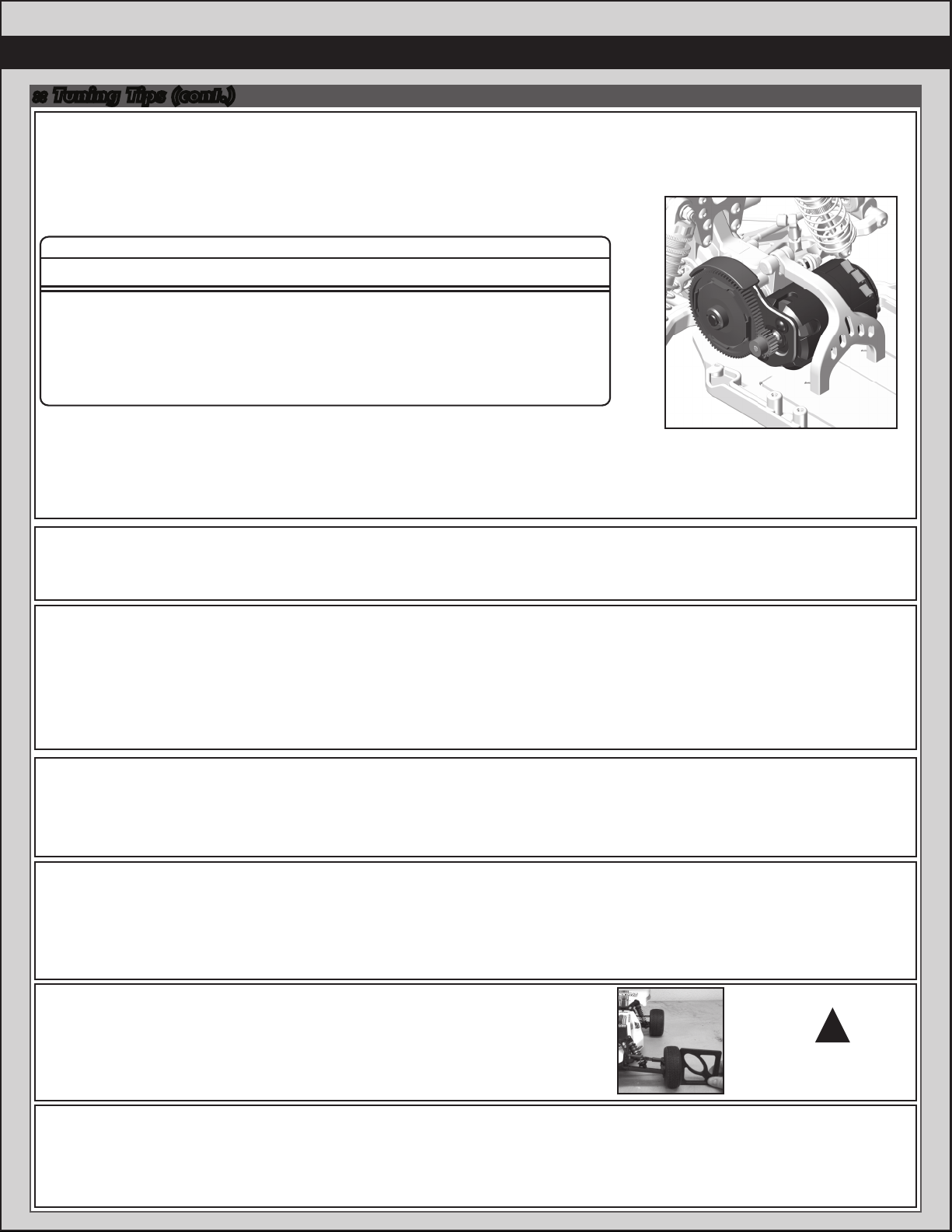
Set The Gear Mesh:
You should be able to rock the spur gear back and forth in the teeth of the pinion gear without making the pinion gear
move. If the spur gear mesh is tight, then loosen the #31532 screws and move the motor away, then try again.
A gear mesh that is too tight or too loose will reduce power and damage the gear teeth.
29
27
24
23
22
21
20
Pinion
72
75
78
78
78
78
78
Spur
6.45:1
7.22:1
8.45:1
8.82:1
9.22:1
9.65:1
10.14:1
Final Drive Ratio
17.5 Reedy S-Plus Brushless
13.5 Reedy S-Plus Brushless
10.5 Reedy 540-M3 Brushless
9.5 Reedy 540-M3 Brushless
8.5 Reedy 540-M3 Brushless
7.5 Reedy 540-M3 Brushless
6.5 Reedy 540-M3 Brushless
Motor
B6 Gear Ratio Chart (Internal Gear Ratio 2.60:1)
Table of contents
Other Team Assocciated Motorized Toy Car manuals

Team Assocciated
Team Assocciated SC10B RS RTR User manual

Team Assocciated
Team Assocciated Nitro TC3 User manual

Team Assocciated
Team Assocciated TEAM ASSOCIATED RC10T4 User manual

Team Assocciated
Team Assocciated RC 12L User manual

Team Assocciated
Team Assocciated Factory Team TC4 User manual

Team Assocciated
Team Assocciated RC10 B3 Factory Team Installation instructions

Team Assocciated
Team Assocciated RC104T4.1 User manual


