Team Assocciated SC10B RS RTR User manual

10/12

2
:: Introduction
:: RTR Features
:: Additional Items Needed: :: Items Included:
:: Other Helpful Items
Associated Electrics, Inc.
26021 Commercentre Dr.
Lake Forest, CA 92630
http://www.TeamAssociated.com · http://www.RC10.com · http://twitter.com/Team_Associated · http://bit.ly/AEonFacebook
Customer Service
Tel: 949.544.7500
Fax: 949.544.7501
Thank you for purchasing this Team Associated product. This assembly manual contains instructions and tips for building and
maintaining your new SC10B RS RTR. Please take a moment to read through this manual to help familiarize yourself with these
steps. We are continually changing and improving our designs; therefore, actual parts may appear slightly different than the
illustrations. New parts will be noted on supplimentary sheets located in the appropriate parts bags. Check each bag for these
sheets before you start your build.
Features of the SC10B RS RTR:
• Fully assembled 2wd short course buggy based on the multi-time National Champion SC10 truck
• Full roll cage with window nets and integral nerf bars
• Water-resistant Brushless Speed Control with reverse
• XP 2.4GHz radio system with metal gear steering servo
• Powerful Reedy 540 sized brushless motor
• Factory finished body with authentic short course graphics
• Cockpit underbody with driver figure
• KMC replica hex drive wheels and aggressive short course tires with new narrow fronts
• Blue anodized aluminum V2 coil-over shock absorbers
• Sealed gear differential with heavy-duty gears
• Molded composite chassis and battery strap that accommodates NiMH or LiPo battery packs
• Water-resistant enclosed receiver box
• Realistic front and rear bumpers designed to absorb impacts
Your new SC10B RTR comes factory assembled including radio
gear, motor, and ESC. However, there are some items you will
need to complete your new kit.
Items needed:
• AA-size batteries for transmitter (x6)
(#302, 303 recommended)
• Battery charger (peak detection charger recommended)
(#610 NiCd/NiMH)(#604, LRP41281, LRP41555 LiPo/LiFe)
• 6 cell NiMH battery pack or 2S LiPo battery pack
w/Deans® Ultra Plug® connector
(#683, 684 NiMH)(#730, 731, 732, 734 LiPo)
Tools included:
• Allen wrenches #6950 (.050”, 1/16”, 5/64” , 3/32”)
• 1.5mm allen wrench
• Molded tools #6956
• Camber gauge #1719
Optional parts and accessories to maintain your SC10B:
• Green Slime shock lube (AE Part # 1105)
• Cyanoacrylate glue (AE Part # 1597)
• Thread Locking Compound (AE Part # 1596)
• Silicone Shock Fluid (Refer to catalog for
complete listings)
• Silicone Diff Fluid (Refer to catalog for
complete listings)
• Body Scissors (AE Part # 1737)
• 8 Piece Hex Driver Set (AE Part # 1655)
• FT Hex Wrenches (AE Part # 1541)
• Hobby Knife
• Needle Nose Pliers
• Wire Cutters
• Soldering Iron
• Calipers or a Precision Ruler
• Reamer / Hole Punch
• FT Nut Driver Set (AE Part # 1561)

3
:: Table of Contents
:: Notes
This symbols indicates a
special note or instruction
in the manual.
!There is a 1:1 hardware foldout page in the back
of the manual. To check the size of a part, line
up your hardware with the correct drawing until
you find the exact size. Each part in the foldout
has a number assigned to it for ordering
replacement parts.
1....................Cover
2....................Introduction
3....................Table of Contents
4 - 5..............Steering System
5 - 8..............Front Suspension
8 - 10...........Transmission
11 - 12........Rear Suspension
13.................Rear Hubs
14 - 15........Shocks
16 - 19........Electronics
19 - 23........Roll cage
24.................Wheels and Tires
25 - 26.......Tuning Tips
27 - 38........Catalog
38.................Contact Information
39................Setup Sheet “RTR Setup”
40.................1:1 Hardware “Fold Out”
41.................Setup Sheet “Blank”
42................Back Cover
Associated Electrics, Inc.
26021 Commercentre Dr.
Lake Forest, CA 92630
http://www.TeamAssociated.com · http://www.RC10.com · http://twitter.com/Team_Associated · http://bit.ly/AEonFacebook
Customer Service
Tel: 949.544.7500
Fax: 949.544.7501

4
:: Steering System
:: Steering System (cont.)
:: Steering System (cont.)
Remove bolt and
washer, continue
assembly per
instructions.
* With supplied wrench, tighten
servo sacer bolt completely, until it
hits bottom. Do not overtighten.
* With supplied
wrench, tighten servo
sacer bolt completely.
Do not overtighten.
!
!
!
9659
Servo saver
(lower)
9659
Servo saver
(lower)
9659
Servo saver
(upper)
9659
Servo saver
(lower)
9610
Servo saver
bolt
9610
Servo saver
bolt
9610
Servo saver
washer
(upper)
9610
Servo saver
washer
(upper)
black grease
#6588
9610
Servo saver
washer
(lower)
9659
Block
carrier
bushing
2221
4-40 x 7/16
bhcs
9659
Bellcrank
6272
Dust cover
foam
9659
Steering
rack
6276
Ballstud
.20 short
(silver)
6276
Ballstud
.20 short
(silver)
6272
Dust cover
foam
9610
Servo saver
washer
(upper)
9610
Servo saver
bolt
9657
Heavy duty
servo saver
spring
x2
x2
x2
x2
x2

5
:: Steering System (cont.)
:: Front Suspension
:: Front Suspension (cont.)
Align the C clip on
the front axles
with the D shape
inside the steering
blocks.
Install the C clip on
the groove shown
below.
Do not overtighten steering
bolts. Make sure there is free
movement in the steering rack.
!
!
!
6272
Foam
dust
cover
3977
3/16 x 3/8
bearing
3977
3/16 x 3/8
bearing
9882
C clip
(3/16”)
7369
1/16”
universal
roll pin
9883
Wheel hex
adapter
(thin)
4449
4-40 x 3/16
aluminum
locknut
9880
Steering
blocks
hex style
(left, right)
4187
.030 washer
(nylon)
3856
Steering
rack bushing
6925
4-40 x 1/2
shcs
6915
4-40 x 5/8
fhcs
6277
Ballstud
.30 long
(silver)
9640
Steering
bolt
(left)
9659
Steering
brace
9881
Front axle
(hex style)
7368
3/16” axle
shim
x2
x4
x3
x2
Build left and
right sides!
Build left and
right sides!
!
!
9640
Steering
bolt
(right)
9563
Front
bulkhead
9823
SC10
chassis
9566
Top plate

6
:: Front Suspension (cont.)
:: Front Suspension (cont.)
:: Front Suspension (cont.)
9622
Outer
hinge pin
9621
Inner
hinge pin
6277
Ballstud
.30 long
(silver)
6292
4-40 x 3/8
fhcs
91202
SC10B
front shock
tower
4334
2-56 x 5/16
bhcs
9645
2-56 x 1/8
bhcs
9645
2-56 x 1/8
bhcs
9580
Spacer
7260
4-40
small
plain nut
7922
Caster
block 30˚
(left, right)
9622
Kingpin
x2
x2 x2
x2
x2
x2
x2
x2
x2
Build left and
right sides!
Build left and
right sides!
6272
Foam
dust
cover
6272
Foam dust
cover
9630
Ballstud
washer,
aluminum
(.030”)
6927
4-40 x 3/4
shcs
6295
4-40 plain
nut
6917
4-40 x 3/8
bhcs
91212
SC10B front
body mount
91200
SC10B
front bumper
(upper)
9564
Front
hinge pin
brace
3983
Ballstud
.30 short
(black)
91201
Front arm
(left, right)

7
:: Front Suspension (cont.)
:: Front Suspension (cont.)
:: Front Suspension (cont.)
91200
SC10B
front bumper
(lower)
91200
SC10B
skid plate
7230
Ball cup
(large)
7230
Ball cup
(large)
7253
2.62
turnbuckle
7101
2.80
turnbuckle
3.48”
(88.3mm)
3.30”
(83.9mm)
7230
Ball cup
(large)
7230
Ball cup
(large)
91220
4-40 x 1 5/8
shcs
6924
4-40 x 3/8
shcs
6915
4-40 x 5/8
fhcs
2221
4-40 x 7/16
bhcs
x4
x2
x2
6915
4-40 x 5/8
fhcs
4-40 x 7/16
x2
x2
x2
x2
Orient the notch to the left throughout
the vehicle. It indicates which end of the
turnbuckle has the left hand threads.
!
Build left and
right sides!

8
:: Front Suspension (cont.)
:: Transmission
:: Transmission (cont.)
Align pin with
groove in
sun gear
!
black grease
#6588
black grease
#6588
black grease
#6588
black grease
#6588
black grease
#6588
black grease
#6588
9765
4-40 x 7/16
fhcs
9828
Diff gear
cover
9828
Diff gear
52T, 48P
9888
0.5mm gear
diff shim
9888
0.5mm gear
diff shim
9830
2x8mm
round end
pin
9830
2x8mm
round end
pin
x4
x2
x2
x2
91205
SC10B
roll cage
bracket
9831
3.6x0.7mm
o-ring
9831
4.7x1.42mm
o-ring
9831
4.7x1.42mm
o-ring
9830
Outdrive
cup
9829
Sun gear
Build left and
right sides!
Build two!

9
:: Transmission (cont.)
:: Transmission (cont.)
:: Transmission (cont.)
Align pin with
groove in
sun gear
!
black grease
#6588
black grease
#6588
black grease
#6588
9829
Planet gear
shims
9829
Planet
gear
9602
Top shaft
spacer
9601
Top
shaft
4675
2.5x6mm
fhcs
x4
x4
x2
x4
9829
Sun gear
9829
Cross pin
Use the 1.5mm allen
wrench to tighten the
2.5x6mm fhcs on the
diff gear cover
Align flat
spots
Ensure free outdrive
rotation before
installation!
!
!
!
!
spacer
9601
Top
shaft
9826
Transmission case
(left, right)
x2
3977
Ball bearing
3/16 x 3/8
3977
Ball bearing
3/16 x 3/8
6919
4-40 x 5/16
bhcs
6925
4-40 x 1/2
shcs
9630
.030 alum.
ballstud
washer
9819
Motor
guard
9832
Ball bearing
10 x 16mm
6928
4-40 x 1
shcs
x2
x2
x2
x2
x3
x3
9831
Diff gear
seal
9360
Idler
gear
9361
Idler gear
shaft

10
:: Transmission (cont.)
:: Transmission (cont.)
:: Transmission (cont.)
9603
Slipper
pad
6915
4-40 x 5/8
fhcs
91203
SC10B
engine bay
side panel
(left, right)
91203
SC10B rear
bumper
6932
4-40 x 5/16
shcs
6924
4-40 x 3/8
shcs
7486
V2 slipper
washer
6913
4-40 x 1 1/4
shcs
x2
x4 x2 x2
x2
x2
x2
91203
SC10B rear
bumper brace
(left, right)
9600
Motor
plate
x2
thread lock
#1596
thread lock
#1596
Compress
spring !
* Install locknut until even with end of
shaft. Then tighten 3 turns for kit
slipper setting. Recheck after initial run. !
!
7485
V2 slipper
hub
9654
Spur gear
(87T, 48P)
6629
5-40
locknut
7486
V2 slipper
spring
x2

11
:: Rear Suspension
:: Rear Suspension (cont.)
:: Rear Suspension (cont.)
9645
2-56 x 1/8
bhcs
x2
x2
x2
9621
Hinge pin
(rear, inner)
9818
Rear chassis
plate
7487
Anti squat
shim
(2 degrees)
7487
Rear arm
mount
(3.5 degrees)
7448
Rear A-arms
(left, right)
x2
x2
9269
5-40 x 1/2
fhcs
6272
Dust cover
foam
6277
Ballstud
.30 long
(silver)
9269
5-40 x 1/2
fhcs
9630
.030 alum.
ballstud
washer
9564
Rear chassis
brace
9643
5-40 x 7/16
shcs
x2
x2
x2
x4
x2
x2

12
:: Rear Suspension (cont.)
:: Rear Suspension (cont.)
:: Rear Suspension (cont.)
9643
5-40 x 7/16
shcs
7260
4-40 small
plain nut
9824
Rear shock
tower
x2
x2
9644
5-40 x 9/16
shcs
6927
4-40 x 3/4
shcs
x2
x2
6928
4-40 x 1
shcs
91212
SC10B rear
body mount
x2
6922
4-40 x 1/2
fhcs
6924
4-40 x 3/8
shcs
x2
x2

13
:: Rear Hubs
:: Rear Hubs (cont.)
:: Rear Hubs (cont.)
LEFT SIDE
SHOWN
6272
Dust cover
foam
7369
1/16
universal
roll pin
9670
Rear axle
3977
Ball bearing
3/16 x 3/8
5407
O-ring 9622
Hinge pin
(rear, outer)
4187
Spacer
7377
Bearing
spacer
7368
3/16 axle
shim
9883
Wheel hex
adapter
9584
Rear hub
carrier
(left, right)
x2
x2
x2
3983
Ballstud
.30 short
(black)
7462
Dogbone
9645
2-56 x 1/8
bhcs
7101
2.80
turnbuckle
7230
Ball cup
(large)
7230
Ball cup
(large)
7260
4-40 small
plain nut
Orient the notch to the left
throughout the vehicle.
It indicates which end of
the turnbuckle has the left
hand threads.
!
!
!
Build left and
right sides!
Build left and
right sides!
Build left and
right sides!
3.58”
(90.9mm)

14
:: Shocks
:: Shocks (cont.)
:: Shocks (cont.)
Piston
Front
Shock
Front
Shock
Front
Shock
Rear
Shock
Rear
Shock
Rear
Shock
Remove
spurs
7217
Pivot
ball
7217
Pivot
ball
7217
Eyelet 7217
Eyelet
6466
Downstop
thin
1/32”
6466
Downstop
thin
1/32”
Piston number here
Use #3 = front shocks
Use #1 = rear shocks
5407
Red
o-ring
6465
Shock
piston
#3
6465
Shock
piston
#1
6299
E-clip
6299
E-clip
6299
E-clip
6299
E-clip
5407
Red
o-ring
9884
V2 RTR
front shock
body 1.02”
stroke
(blue)
9885
V2 RTR
front shock
body 1.39”
stroke
(blue)
7484
Shock
internal
spacer
6459
Shock
shaft
1.02”
stroke
6458
Shock
shaft
1.32”
stroke
7484
Shock
internal
spacer
6469
Shock
cap
o-ring
6469
Shock
cap
o-ring
7484
Lower shock
seal cap
7484
Lower shock
seal cap
x5 x2

15
:: Shocks (cont.)
:: Shocks (cont.)
:: Shocks (cont.)
* Shock Bleeding Steps:
1. Pull shock shaft down.
2. Fill shock body 3/4 full with silicone fluid.
3. Slowly move the shock shaft up and
down to remove air from under piston.
4. Wait for bubbles to come to surface.
5. Fill shock body to top with silicone fluid.
6. Place several drops of oil in the cap and
on cap threads.
7. Install cap and tighten completely.
8. Slowly compress shaft all the way to
the top. If there is pressure at the top
of the stroke, there is too much oil or air.
You must bleed it out.
9. Slowly pull shaft down.
10. Unscrew the cap 3/4 turn and tilt the
shock at a slight angle.
11. Slowly compress the shaft to push out
excess oil and air. You should see
bubbles coming out from under the cap.
12. With the shaft compressed, tighten the
cap and re-check for pressure at the top
of the stroke. If there is still pressure,
repeat steps 9 thru11.
Step 7Step 5-6Step 3-4Step 1-3
7425
Front
spring
(gold)
3.70lb
6480
Rear
spring
(green)
1.90lb
6475
Spring
collar
6475
Spring
collar
8846
Preload
spacers
6927
4-40 x 3/4
shcs
6472
Shock
mount nut
6473
Shock
bushing
6473
Shock
bushing
8846
Preload
spacers
6441
Shock
cap
(molded)
6475
Spring
cup
6475
Spring
cup
Shock fluid
30wt #5422
Shock fluid
30wt #5422
Front
Shock
Rear
Shock
Front x2 Rear x2
6925
4-40 x 1/2
shcs
6472
Shock
mount nut
Build left and
right sides!
!
.02
x1
.25
x2
.12
x1
x1
.02
x1
.12
x1
.03

16
:: Electronics
:: Electronics (cont.)
:: Electronics (cont.)
6917
4-40 x 3/8
bhcs
7336
Servo
spacers
7336
Servo
mount
7337
Gold
washer
9170
Servo
link
3981
Ballstud
.20 short
(black)
6272
Dust cover
foam
x4
x2
x2
x4
8255
18T 48P
pinion gear
w/setscrew
9180
Servo horn
Servo
See page 40 for
correct servo
horn on the
servo chart
Screw supplied
with servo
!
See page 40 for
correct servo
spacing on the
servo chart
Leave a
1/16 gap
!
!6292
4-40 x 3/8
fhcs
x2
6285
4-40 x 1/4
shcs
31531
M3 x 6mm
bhcs
6936
Washer #4
aluminum
7460
Gear cover
w/button
(black)
x2
x2
x2
Motor
See page 25 for
gear mesh setting
instructions.
!

17
:: Electronics (cont.)
:: Electronics (cont.)
:: Electronics (cont.)
!
!
!
!
9877
Receiver
box
(bottom)
9643
5-40 x 7/16
shcs
6727
Servo
tape
Speed Control
(ESC)
9878
Wire
grommet
plug
Receiver
9878
Receiver
box
grommet
Receiver grommet plug
can be removed if you use
a personal transponder!
Install the ESC and servo
wires into the wire
grommet before installing
the grommet into the
receiver box!
You may need to reposition
the receiver in order to
geit it to fit with the plugs
installed and the receiver
box lid installed.
Once you find a good fit,
use #6727 servo tape to
install your receiver.

18
:: Electronics (cont.)
:: Electronics (cont.)
9815
foam
spacer
9643
5-40 x 7/16
shcs
9879
4-40 x 1/2
setscrew
9879
Thumb
knob
3862
5-40 x 1/8
setscrew
6338
Antenna
and cap
9879
Battery
strap
Batttery
(Not included)
9878
Receiver
box seal
x2
x2
x2
9877
Receiver
box (top)
Leave
no gap!
You can trim the foam
to move the battery
pack and adjust the
weight balance of the
vehicle!
To install the battery
strap, slide the back
section in between
the top of the battery
and the bottom of the
shock tower!
!
!
!
!
!
9146
2-56 x 3/16
bhcs
x3
91214
SC10B
body, clear
Install left and
right sides!

19
:: Electronics (cont.)
:: Rollcage
Unlocked Locked
To remove your battery pack from the vehicle, twist the thumb knobs to the
unlocked position, remove the battery strap, and then remove the battery.
When you install the battery, make sure the thumb knobs are locked before
operation.
You may need to adjust the height of the thumb knobs and/or the set
screws that the thumb knobs are attached to for your specific battery
pack type.
6919
4-40 x 5/16
bhcs
x2
9146
2-56 x 3/16
bhcs
6927
4-40 x 3/4
shcs
x2
x2
91204
SC10B
roll cage
side panel
(left, right)
91204
SC10B
roll cage
rear panel
(left, right)
91208
SC10B
window
nets
Build left and
right sides!
Note placement of window net tab!
Note placement of window net tab!

20
:: Rollcage (cont.)
:: Rollcage (cont.)
:: Rollcage (cont.)
6925
4-40 x 1/2
shcs
6927
4-40 x 3/4
shcs
6927
4-40 x 3/4
shcs
6924
4-40 x 3/8
shcs
6924
4-40 x 3/8
shcs
91204
SC10B roll cage
rear body
mount bar
6927
4-40 x 3/4
shcs
6927
4-40 x 3/4
shcs
91206
SC10B
rollcage
roof
91204
SC10B
roll cage
front panel
(left, right)
91204
SC10B
roll cage
hood
x2
6925
4-40 x 1/2
shcs
x2
6925
4-40 x 1/2
shcs
x2
Table of contents
Other Team Assocciated Motorized Toy Car manuals

Team Assocciated
Team Assocciated TEAM ASSOCIATED RC10T4 User manual
Team Assocciated
Team Assocciated Nitro TC3 User manual
Team Assocciated
Team Assocciated RC10B6.1 Dirt Light Team Kit User manual

Team Assocciated
Team Assocciated RC104T4.1 User manual
Team Assocciated
Team Assocciated RC 12L User manual

Team Assocciated
Team Assocciated Factory Team TC4 User manual
Team Assocciated
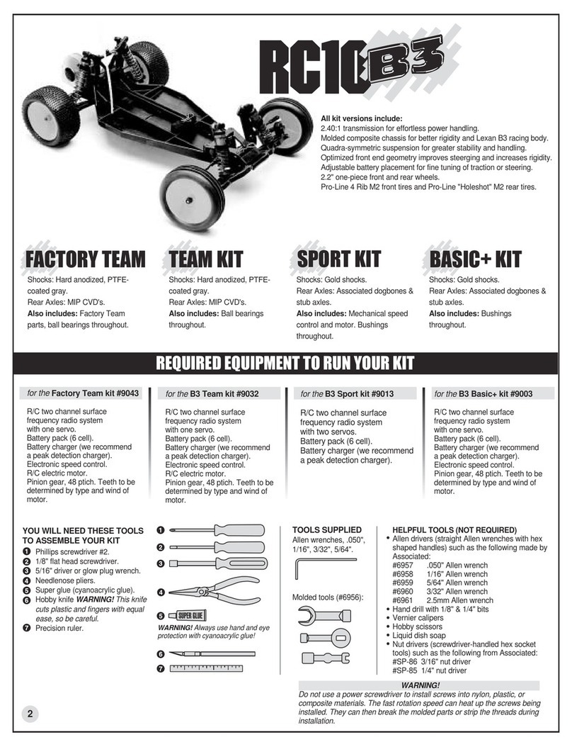
Team Assocciated RC10 B3 Factory Team Installation instructions
