Team SILK AX48-120 User manual

INSTRUCTION MANUAL
AX48-120 FLANGE FACING MACHINE
Revision D
TEAM®
Shap Road
Kendal
Cumbria
LA9 6RU
United Kingdom
Tel: +44 (0) 1539 729009
Fax: +44 (0) 1539 729359
TEAM® is an ISO9001 registered company
© Copyright 2022 TEAM®

AX48-120 Flange Facing Machine
1
THIS INSTRUCTION MANUAL
This Instruction Manual describes how to safely install, operate and maintain the AX48-120
Flange Facing Machine. It is an essential part of the equipment and it is important that you
take the time to read it thoroughly.
Additional copies are available for purchase from TEAM® or from an authorised agent.
HEALTH AND SAFETY AT WORK
This document should be read carefully and fully understood before proceeding to install,
use, maintain or service the equipment.
DO NOT USE THE EQUIPMENT UNTIL YOU ARE SURE YOU KNOW HOW IT WORKS
AND WHAT ITS INTENDED FUNCTION IS.
The equipment described in this document is intended to be used by professional personnel
in an industrial environment.
Installation, operation, maintenance and servicing should only be carried out by suitably
qualified and experienced personnel.
The following symbols are used to highlight important areas of this document which relate to
potential hazards and residual risks:
Important statements regarding the use, handling or operation
of the equipment.
Warnings to prevent injury to operator and or local personnel.
Cautions to prevent misuse and damage to the equipment.
IMPORTANT NOTICE
TEAM® has made every effort to ensure that the information given in this document is as
accurate and as up-to-date as possible at the time of publication.
TEAM® will not be held responsible for any accident or equipment failure that may occur due
to misuse, unauthorised modification, inadequate maintenance, use of non-genuine parts or
use by unsuitable personnel.
TEAM® reserves the right to update, correct or otherwise change any information relating to
this equipment, at any time and without obligation.

AX48-120 Flange Facing Machine
2
TEAM® also reserves the right not to provide updated, corrected or amended versions of this
publication.
The specification and design of the AX48-120 Flange Facing Machine (including the
copyright, design right or other intellectual property in them) shall, at all times, remain the
property of TEAM®. Where any designs or specifications have been supplied by the client for
manufacture by TEAM® or to the order of the client then the client warrants that the use of
those designs or specifications for the manufacture, processing, assembly or supply of the
AX48-120 Flange Facing Machine shall not infringe the rights of any third party.
WARRANTY, SPARES AND AFTER SALES SERVICE
Subject to the provisions of any bespoke terms and conditions of sale, this AX48-120 Flange
Facing Machine is guaranteed for twelve (12) months from the date of purchase against
faulty materials and/or workmanship. During this period it will be repaired or have parts
replaced free of charge provided that:
1 it is returned immediately to TEAM® with evidence of the purchase date;
2 it has been purchased by the user and has not been used for hire purposes;
3 it has not been misused or handled carelessly and has been stored and maintained in
accordance with any instructions provided by TEAM®;
4 repairs have not been attempted other than by a member of TEAM® service team or by a
service provider duly authorised by TEAM® to carry out such repairs; and
5 the cost of such repair or replacement does not exceed the original purchase value.
A full spare parts service is available from TEAM® or from an authorised agent. Additionally,
TEAM® can supply a recommended spare parts kit suitable for a specified period of normal
service life.
Also offered is a Factory Service, in which the equipment can be returned to TEAM® for
inspection. A quotation may then be given for the overhaul, repair or replacement of the
equipment.
TEAM® warrants that the AX48-120 Flange Facing Machine supplied will at the time of
delivery correspond to the description given by TEAM®. All other warranties, conditions or
terms relating to fitness for purpose, quality or condition of the AX48-120 Flange Facing
Machine, whether express or implied by statute or common law or otherwise are excluded to
the fullest extent permitted by law.

AX48-120 Flange Facing Machine
3
CONTENTS
SECTION 1 TECHNICAL DESCRIPTION ........................................................................... 8
1.1 Introduction ...................................................................................................... 8
1.2 Equipment description ..................................................................................... 8
1.2.1 Turntable assembly ............................................................................... 8
1.2.2 Feed gearbox ......................................................................................10
1.2.3 Surfacing arm assembly and toolpost .................................................10
1.2.4 Mounting base assembly ....................................................................11
1.2.5 Optional accessories ...........................................................................12
SECTION 2 SPECIFICATIONS .........................................................................................13
SECTION 3 SAFETY INFORMATION ..............................................................................16
3.1 Warnings and cautions ..................................................................................16
SECTION 4 CONTROLS AND BASIC OPERATION .......................................................19
4.1 Location and function of the controls.............................................................19
4.1.1 Machine controls .................................................................................19
4.1.2 Filter/lubricator pack controls ..............................................................21
4.2 Basic operation of the equipment ..................................................................22
4.3 Lifting and slinging arrangements .................................................................22
SECTION 5 SITE OPERATION .........................................................................................23
5.1 Warnings and cautions ..................................................................................23
5.2 Setting up the equipment ..............................................................................24
5.2.1 Unpacking the machine .......................................................................24
5.2.2 Mounting base installation ...................................................................26
5.2.3 Centralising the base within the bore ..................................................29
5.2.4 Machine installation .............................................................................30
5.2.5 Setting up the tool ...............................................................................32
5.2.6 Toolpost overrun and gearbox protection device ................................32
5.2.7 Installing and machine balancing - (vertical flange) ............................33
5.2.8 Setting up the tool - facing and grooving ............................................36
5.3 Using the equipment......................................................................................37
5.3.1Connection to Air Supply .....................................................................37
5.3.2 Starting the machine - Facing and Grooving ......................................38
5.4 Removing the equipment ..............................................................................39
5.5 Storing the equipment ...................................................................................39
SECTION 6 FAULT DIAGNOSIS ......................................................................................40
6.1 Introduction ....................................................................................................40
6.2 Fault diagnosis chart .....................................................................................40
SECTION 7 MAINTENANCE INSTRUCTIONS ................................................................42
7.1 Introduction ....................................................................................................42
7.2 Periodic maintenance ....................................................................................42
7.3 Recommended lubricants ..............................................................................43
7.4Removal and refit procedures .......................................................................44
7.4.1 Drive motor ..........................................................................................44
7.4.2 Removal of gearbox ............................................................................44
7.4.3 Replacement of shear pins .................................................................45
7.4.4 Surfacing arm ......................................................................................46

AX48-120 Flange Facing Machine
4
7.4.5 Toolpost ...............................................................................................47
7.4.6 Toolpost overrun/gearbox protection device .......................................48
SECTION 8 PARTS LISTS ................................................................................................49
8.1 Mast and turntable assembly ........................................................................52
8.2 Surfacing arm assembly ................................................................................56
8.3 Gearbox assembly.........................................................................................59
8.4 Base assembly ..............................................................................................62
8.5 Toolpost assembly.........................................................................................64
8.6 Base centraliser .............................................................................................66
8.7 Counter balance ............................................................................................68
APPENDIX A Cutting tools as applied to portable machines .........................................69
APPENDIX B Surface metrology .......................................................................................72
APPENDIX C V-Groove measurement ..............................................................................75
APPENDIX D Air motor manufacturers information ........................................................77
APPENDIX E Fall-Stop Kit ..................................................................................................84
1. Technical description .....................................................................................84
2. Specifications .................................................................................................85
3. Safety information ..........................................................................................85
4. Installation of the equipment ..........................................................................86
5. Operation of the equipment ...........................................................................88
6. Maintenance instructions ...............................................................................88
7. Periodic maintenance ....................................................................................89
APPENDIX F Declaration of Conformity ...........................................................................90
AX48-120 Flange Facing Machine
5
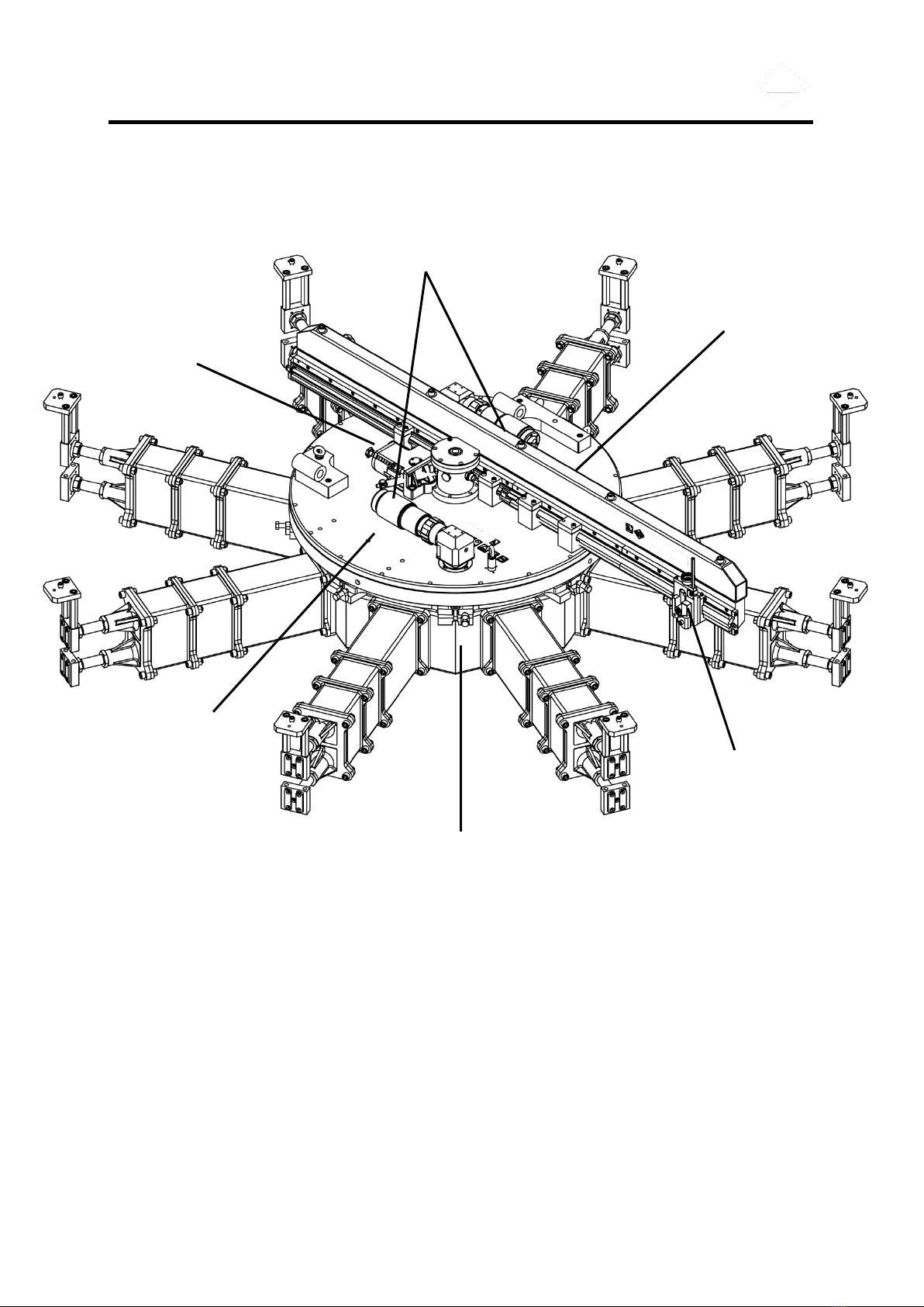
Fig. 1 AX48-120 Flange Facing Machine – full assembly
Drive motors
Surfacing arm
assembly
Mounting base
assembly
Feed
Gearbox
Toolpost
Turntable
Assembly
AX48-120 Flange Facing Machine
6
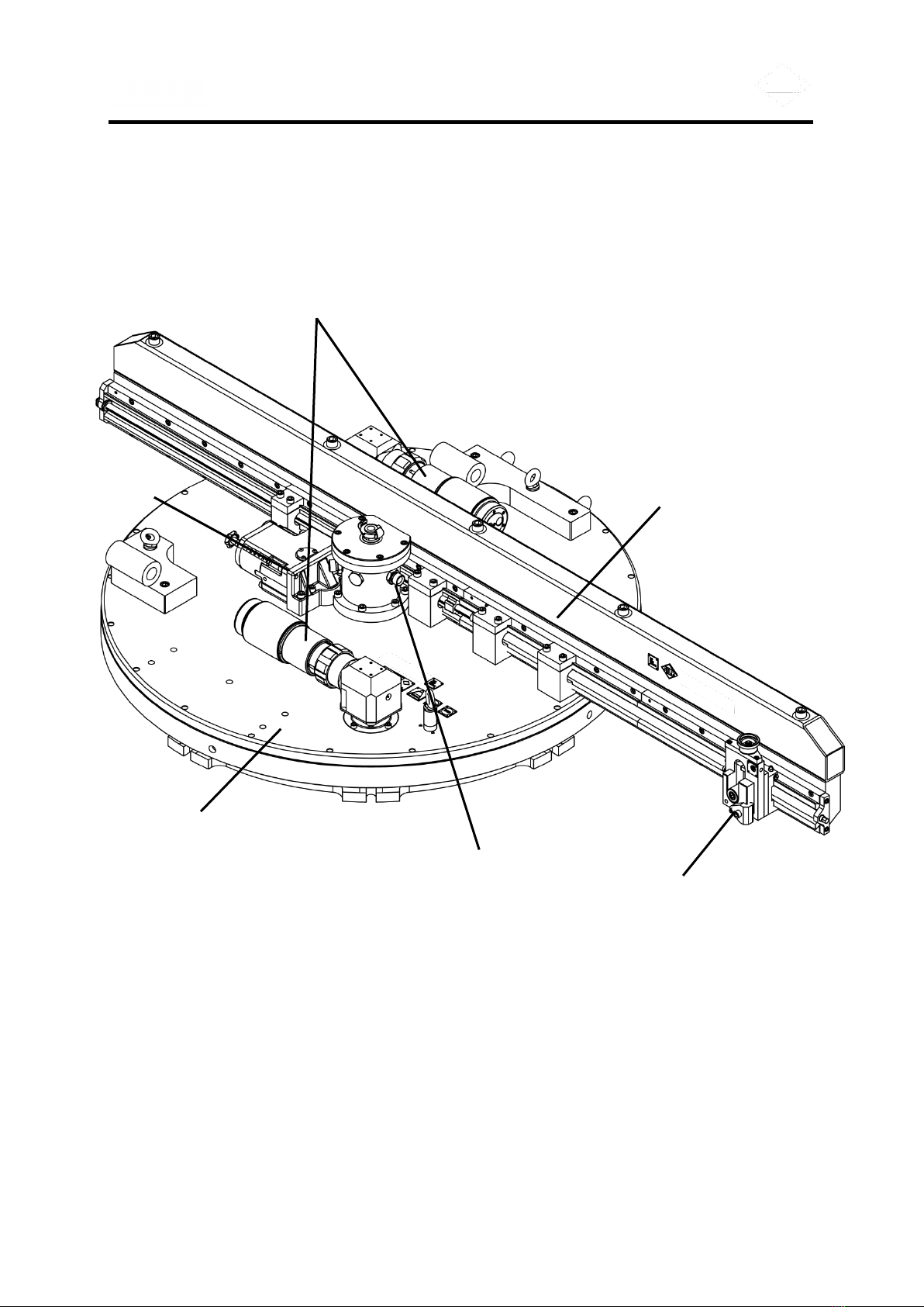
Fig. 2 AX48-120 Flange Facing Machine – turntable and machining arm assemblies
Drive motors
Surfacing arm
assembly
Mast
Toolpost
Turntable
Assembly
Feed
Gearbox

AX48-120 Flange Facing Machine
7
Fig. 3 AX48-120 Flange Facing Machine – exploded view
Drive motors
Surfacing arm
assembly
Mounting base
assembly
Feed
Gearbox
Toolpost
Turntable
Assembly

AX48-120 Flange Facing Machine
8
SECTION 1 TECHNICAL DESCRIPTION
1.1 INTRODUCTION
The TEAM® AX48-120 Flange Facing Machine is constructed from the highest quality
materials and great care has been taken in its design and manufacture. Its design will give
every satisfaction provided that it is properly installed, operated and maintained in
accordance with the information contained within this manual.
Take care of this manual; it is an essential source of information.
1.2 EQUIPMENT DESCRIPTION
The AX48-120 Flange Facing Machine is designed to machine full face, raised face and
grooved flanges from 1220mm to 3048mm (48" to 120") in diameter at any location having a
minimum pneumatic air supply of 5.8 m3/m at 6 bar (205 cfm, 90 psi).
The machine can achieve a variety of surface finishes from 6.3μm RA to 1.6μm RA when
turning and 1.6μm RA to 0.8μm RA when polishing. The machine can also produce a
'gramophone' finish, 'O' ring grooves, and 'V' grooves.
The machine consists of 4 main assemblies:
1. Turntable assembly
2. Feed gearbox
3. Surfacing arm assembly
4. Mounting base assembly
1.2.1 Turntable assembly
The turntable assembly consists of:
1. Turntable
2. Base plate sub assembly

AX48-120 Flange Facing Machine
9
Fig. 4 Turntable assembly
1. Turntable
The turntable is the rotating part of the machine providing a rigid support for the
surfacing arm assembly.
The drive for the turntable is supplied by two air motors through 90° bevel
gearboxes directly onto the turntable ring gear. Air for the motors is supplied via a
central connection on the mast through a rotary seal. The mast remains stationary
during operation.
2. Base plate sub assembly
The base plate sub assembly is the fixed part of the turntable assembly and
comprises of a base plate which is clamped to the mounting base assembly, a
mast gear used for the gearbox drive, and a central mast which supplies air to the
rotary air sealing cartridge. At the top of the central mast a quick release air
coupling is attached.
Drive motor
Feed gearbox
Turntable
Base plate
sub assembly
Mast
Drive motor

AX48-120 Flange Facing Machine
10
1.2.2 Feed gearbox
The feed gearbox is mounted on the turntable assembly and provides a variety of
cutting feeds for different machine applications. Drive from the feed gearbox to the
toolpost is via the surfacing arm leadscrew.
Drive input to the feed gearbox is derived from the mast transfer gear. The gearbox
provides four different feed rates, selected via the cutting feed rate push/pull
selector. Traverse direction is selected via the traverse direction push/pull selector,
which selects traverse IN, traverse OUT and neutral N position. The neutral (N)
position can be used for manually positioning of the toolpost and tool. An additional
neutral (N) position is also available by pushing the cutting feed rate selector fully
inwards past the No.4 feed position. This enables the operator to easily disengage
the feed gearbox from any feed.
Fig. 5 Feed gearbox
1.2.3 Surfacing arm assembly and toolpost
The surfacing arm assembly is mounted on the turntable assembly and provides a
rigid structure to which the tool post is secured. The arm can be positioned at any
diameter within the recommended facing range.
Toolpost feed in and out is provided by a leadscrew which is driven by the gearbox
pickup gear. The surfacing arm assembly can achieve cuts to a maximum depth of
1.0mm (0.040in) in flanges without bolt holes and 0.5mm (0.02in.) with bolt holes.
Alternative tools can be fitted to the tool post depending on the finish and cut
required.
Traverse
direction
selector
Cutting feed
rate selector

AX48-120 Flange Facing Machine
11
Fig. 6 Surfacing arm assembly and toolpost
1.2.4 Mounting base assembly
The mounting base assembly is provided to enable the machine to be installed in
the centre of a flange.
The mounting base assembly consists of a rigid central unit with eight radial
location bosses. The bosses allow extension legs and the clamping jaw assemblies
to be fitted to the base to suit the internal diameter of the flange to be machined.
The extension legs are precision manufactured to ensure perfect alignment when
fitted correctly.
The design and manufacture of the base and extension legs ensures a rigid
machine mounting structure. The rigid structure results in a precise distance from
each setting bracket mounting face to the corresponding machine support pad on
top of the mounting base. This allows any flange surface height deviation to be
averaged out over the eight legs thus reducing levelling adjustment to a minimum.
The mounting base is usually installed in the flange bore prior to the machine
installation.
Toolpost
Tool holder
Drive shaft
Pickup gear
(PTO)
Lead screw

AX48-120 Flange Facing Machine
12
–
Fig. 7 Mounting base assembly
1.2.5 Optional accessories
The following optional accessories are available upon request:
V-Groove machining kit
V-Groove measuring kit
Tube sheet machining kit
Tube sheet measuring kit
Lens ring machining kit
Fall stop kit
Setting strap
plate
Spigot
location hole
Threaded
collar
Short
extension leg
Long
extension leg
Clamping
jaws
Ram bolt

AX48-120 Flange Facing Machine
13
SECTION 2 SPECIFICATIONS
Fig. 8 Principal dimensions
PRINCIPAL DIMENSIONS:
Overall machine height
695 mm
27.4"
Mounting base thickness
290 mm
11.4”
Minimum mounting base diameter
1296 mm
51.0”
Minimum rotational diameter
2300 mm
90.6”
Flange depth required to set base using standard parts
Machine height above tube sheet on mounting plate
395 mm
432 mm
15.6”
17.0”
WEIGHTS:
Turntable and surfacing arm weight
Turntable and surfacing arm weight (With Fall Stop Kit)
681 kg
765 kg
1501 lbs
1686 lbs
Base weight (minimum diameter)
381 kg
840 lbs
Base weight (maximum diameter)
671 kg
1479 lbs
Counter balance total weight
67 kg
148 lbs
405 mm
(15.9”)
Mounting
base
thickness
290mm
(11.4”)
Overall
machine
height
695mm
(27.4”)
Minimum
depth of
flange
required
395mm
(15.6”)

AX48-120 Flange Facing Machine
14
TRANSPORTATION DIMENSIONS:
MACHINE
BASE
Net weight (without transport case)
681 kg
1501 lbs
671 kg
1479 lbs
Gross weight (including transport case)
935 kg
2061 lbs
835 kg
1840 lbs
Case dimensions
Length
2500mm
98”
1400mm
55”
Height
700mm
28”
900mm
35”
Width
1400mm
55”
1400mm
55”
OPERATIONAL DIMENSIONS:
Facing range:
Minimum diameter
1220 mm
48.0”
Recommended maximum diameter
3048 mm
120.0"
Gripping range:
Minimum recommended bore
1308 mm
51.5"
Maximum recommended bore
3052 mm
120.0"
Toolpost travel
40 mm
1.6"
Gearbox feed rate (per revolution):
Position 1
0.18 mm
0.007"
Position 2
0.25 mm
0.010"
Position 3
0.46 mm
0.018"
Position 4
0.84 mm
0.033"
Position ‘N’
neutral
Turntable free running speed
13 rpm ± 10%
NOISE EMISSION:
Emission sound pressure level
88 dB
Instantaneous sound pressure value. Indicate either
less than 63 Pa (130 dB) or actual value if above.
<130dB
Emission sound power level. Indicate either less than 80
dB (A) or actual value if above.
94dB(A)

AX48-120 Flange Facing Machine
15
MOTOR INFORMATION:
Type: MODEC
MR30LT0133ECL1F
Power output
3.0 kW
4.0 hp
Maximum speed free running
256 rpm
Speed at maximum output
129 rpm ± 10%
Recommended air supply
5.8 m3/min
205 cfm
6.0 bar
90 psi
Air inlet thread
3/4" BSP

AX48-120 Flange Facing Machine
16
SECTION 3 SAFETY INFORMATION
3.1 WARNINGS AND CAUTIONS
GENERAL:
ALL SAFETY PROCEDURES MUST BE OBSERVED AND STRICTLY
ADHERED TO WHEN INSTALLING, USING, MAINTAINING AND
SERVICING THIS EQUIPMENT.
ONLY TRAINED AND COMPETENT PERSONNEL SHOULD INSTALL,
USE, MAINTAIN AND SERVICE THIS EQUIPMENT.
ENSURE AN EMERGENCY STOP IS ALWAYS WITHIN REACH OF THE
OPERATOR.
INTENDED USE OF THIS EQUIPMENT:
THIS EQUIPMENT IS FOR USE BY PROFESSIONAL, TRAINED
PERSONNEL WORKING IN AN INDUSTRIAL ENVIRONMENT.
THIS EQUIPMENT IS INTENDED FOR USE ON METALS AND
ANALOGOUS SUBSTANCES.
THIS EQUIPMENT IS NOT INTENDED FOR USE ON WOOD, PLASTIC OR
SIMILAR ANALOGOUS SUBSTANCES.
USE OUTDOORS:
THIS EQUIPMENT SHOULD NOT BE USED DURING SEVERE WEATHER
CONDITIONS.
PERSONNEL SHOULD NOT OPERATE THIS EQUIPMENT IN WEATHER
CONDITIONS WHICH MAY GIVE RISE TO THE FOLLOWING:
- INADEQUATE VISIBILITY
- THE BUILD-UP OF ICE, SNOW, WATER, SAND OR DUST ON
PLATFORMS, LADDERS, CONTROLS, VISUAL INDICATORS,
MOVING PARTS, ETC.
- RISK OF INJURY DUE TO STRONG OR GUSTING WINDS
THIS EQUIPMENT SHOULD BE SUITABLY PROTECTED FROM ALL
SEVERE WEATHER CONDITIONS.

AX48-120 Flange Facing Machine
17
PERSONAL PROTECTIVE EQUIPMENT:
THE USE OF PERSONAL PROTECTIVE EQUIPMENT IS
RECOMMENDED WHEN WORKING WITH THIS EQUIPMENT.
SUGGESTIONS INCLUDE SAFETY HAT, GAUNTLET GLOVES, SAFETY
GOGGLES, SAFETY SHOES, AND FLAME RETARDANT COVERALLS.
BREATHING APPARATUS MAY BE NECESSARY WHEN A TOXIC
ATMOSPHERE EXISTS.
OTHER PROTECTIVE EQUIPMENT MAY BE REQUIRED AS PER THE
PLANT OPERATOR’S REQUIREMENTS.
PERSONNEL WORKING ABOVE GROUND LEVEL MUST ALSO WEAR A
SAFETY HARNESS CONNECTED TO A SUITABLE ANCHOR POINT OR
FALL ARRESTOR.
LIFTING:
ENSURE LIFTING IS CARRIED OUT IN A SAFE AND PROPER MANNER,
IN ACCORDANCE WITH APPLICABLE HEALTH AND SAFETY
REGULATIONS.
ALWAYS KNOW THE WEIGHT OF THE EQUIPMENT AND THE
COMPONENT PARTS. REFER TO THE SPECIFICATION PAGE IN THIS
MANUAL OR THE MARKING PLATE ON THE EQUIPMENT.
THE USE OF MECHANICAL LIFTING DEVICES MAY BE A MANDATORY
REQUIREMENT FOR LIFTING THIS EQUIPMENT.
INSTALLATION AND REMOVAL:
THIS EQUIPMENT IS INTENDED TO BE PORTABLE AND MAY BE USED
IN A VARIETY OF LOCATIONS AND ORIENTATIONS. ALWAYS ENSURE
THAT THIS EQUIPMENT IS PROPERLY SUPPORTED AND RESTRAINED
DURING THE INSTALLATION AND REMOVAL PROCESS.
IF THE INSTALLATION, REMOVAL OR MACHING ACTIVITY IS TAKING
PLACE OVER AN OPEN HOLE, A FLANGE BORE FOR EXAMPLE, AND
THERE IS A RISK OF THE EQUIPMENT FALLING INTO THE OPENING.
THE MACHINE MUST BE FITTED WITH THE FALL-STOP ACCESSORY
KIT SUPPLIED TO PREVENT INJURY OR DAMAGE - SEE APPENDIX ‘E’
FOR DETAILS.

AX48-120 Flange Facing Machine
18
PNEUMATICS:
ENSURE THE CORRECT HOSES, VALVES AND FITTINGS ARE USED.
DO NOT PRESSURISE THIS EQUIPMENT IF ANY OF THE HOSES,
VALVES OR FITTINGS ARE LEAKING OR DAMAGED.
DO NOT PRESSURISE THIS EQUIPMENT UNTIL YOU ARE SURE THE
EQUIPMENT HAS BEEN CORRECTLY INSTALLED AND THE CONTROL
VALVES ARE CLOSED.
DO NOT USE AIR MOTORS WITH DEFECTIVE SILENCERS. THIS MAY
CAUSE UNNECESSARY NOISE AND IMPAIR THE PERFORMANCE OF
THE EQUIPMENT.
NEVER PLACE ANY BODY PARTS ADJACENT TO AN AIR EXHAUST.
COMPRESSED AIR FORCED INTO THE SKIN IS DANGEROUS AND MAY
RESULT IN A SERIOUS SKIN DISORDER.
ENSURE THE PNEUMATIC SYSTEM IS ISOLATED AND DE-
PRESSURISED BEFORE MAKING ANY ADJUSTMENTS TO THIS
EQUIPMENT.
ENSURE THE PNEUMATIC SYSTEM IS ISOLATED AND DE-
PRESSURISED BEFORE DISCONNECTING ANY HOSES.
DO NOT ALLOW THE LUBRICATOR TO SUPPLY EXCESSIVE AMOUNTS
OF OIL TO THE PNEUMATIC SYSTEM. 5 TO 6 DROPS PER MINUTE AT
FULL MOTOR SPEED IS RECOMMENDED.
NEVER LEAVE THE PNEUMATIC SYSTEM PRESSURISED WHILE
UNATTENDED.
AX48-120 Flange Facing Machine
19
SECTION 4 CONTROLS AND BASIC OPERATION
4.1 LOCATION AND FUNCTION OF THE CONTROLS
The following controls are incorporated into the machine:
4.1.1 Machine controls
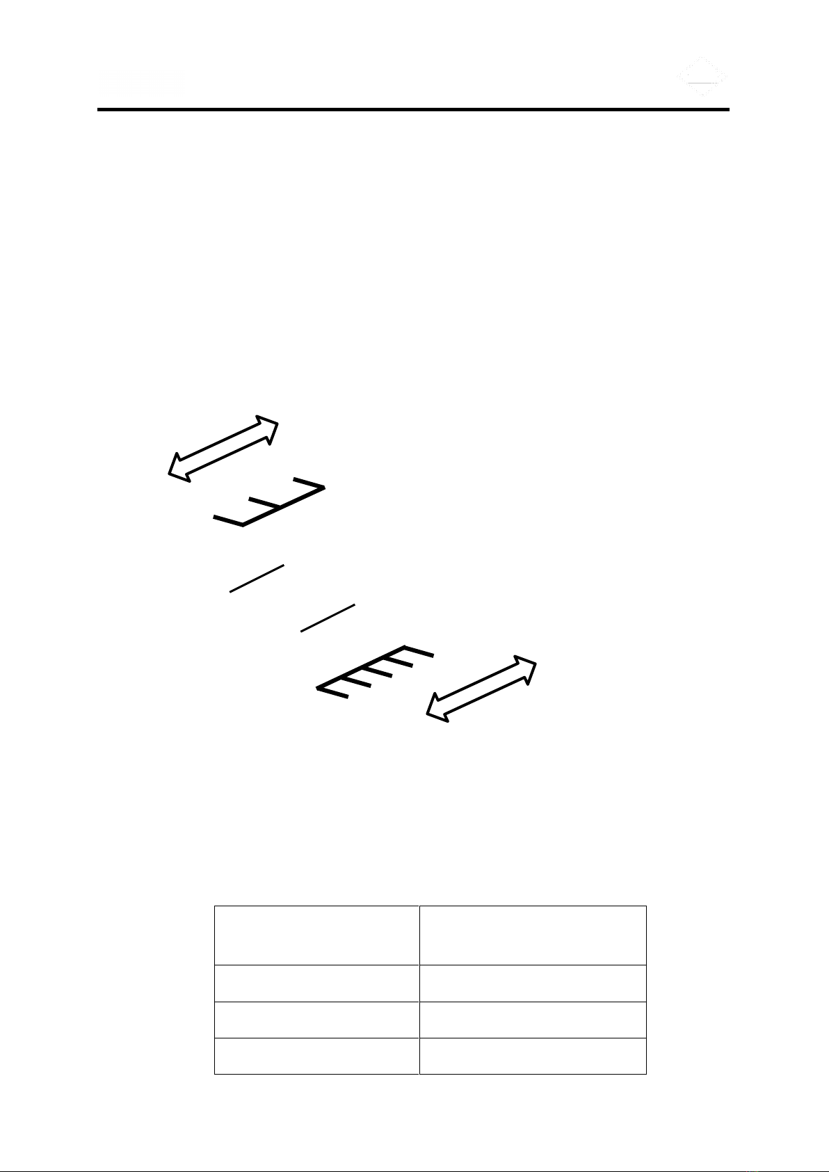
Fig. 9 Machine controls
Traverse direction selector
Selects the direction of the toolpost as it traverses across the work piece. The fully
pulled out position ‘N’ disengages the traverse feed.
TRAVERSE DIRECTION
SELECTOR POSITION
TOOL DIRECTION
FEED IN
(selector fully pushed in)
Towards centre of work piece
FEED OUT
(selector in central position)
Away from centre of work piece
NEUTRAL (N)
(selector fully pulled out)
No movement
Traverse
direction
selector
Cutting feed
rate selector
FEED
OUT
FEED IN
NEUTRAL
N
1
2
3
4
NEUTRAL
N
Table of contents
Other Team Industrial Equipment manuals


Popular Industrial Equipment manuals by other brands

Minebea Intec
Minebea Intec Inteco PR 6203 installation manual

Endress+Hauser
Endress+Hauser Soliwave FQR56 operating instructions

Virutex
Virutex PR25VJ operating instructions

Stahl
Stahl SolConeX 8573/14 Series operating instructions

CNC
CNC RAPTOR XPR user guide

SMC Networks
SMC Networks MHZ2-6C-M9PLS Operation manual


