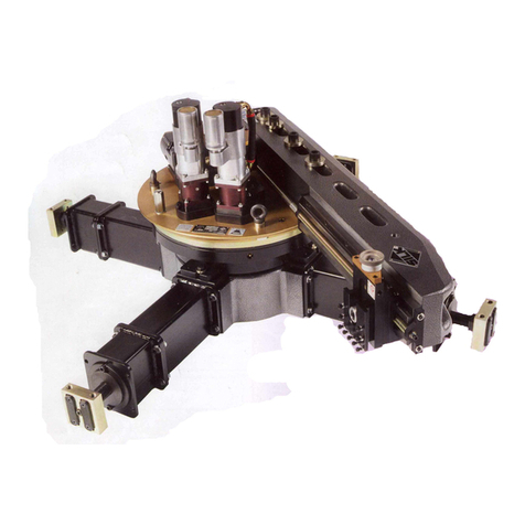
Team SILK AX08 User manual

INSTRUCTION MANUAL
AX08 FLANGE FACING
AND GROOVING MACHINE
Revision A
TEAM®
Shap Road
Kendal
Cumbria
LA9 6RU
United Kingdom
Tel: +44 (0) 1539 729009
Fax: +44 (0) 1539 729359
TEAM® is an ISO9001 registered company
© Copyright 2022 TEAM®

AX08 Flange Facing and Grooving Machine
1
THIS INSTRUCTION MANUAL
This Instruction Manual describes how to safely install, operate and maintain the AX08
Flange Facing and Grooving Machine. It is an essential part of the equipment and it is
important that you take the time to read it thoroughly.
Additional copies are available for purchase from TEAM® or from an authorised agent.
HEALTH AND SAFETY AT WORK
This document should be read carefully and fully understood before proceeding to install,
use, maintain or service the equipment.
DO NOT USE THE EQUIPMENT UNTIL YOU ARE SURE YOU KNOW HOW IT WORKS
AND WHAT ITS INTENDED FUNCTION IS.
The equipment described in this document is intended to be used by professional personnel
in an industrial environment.
Installation, operation, maintenance and servicing should only be carried out by suitably
qualified and experienced personnel.
The following symbols are used to highlight important areas of this document which relate to
potential hazards and residual risks:
Important statements regarding the use, handling or operation
of the equipment.
Warnings to prevent injury to operator and or local personnel.
Cautions to prevent misuse and damage to the equipment.

AX08 Flange Facing and Grooving Machine
2
IMPORTANT NOTICE
The contents of this manual, including the graphics contained herein, are solely intended for the use of
the original purchaser. Information and data contained in this manual is exclusively for the purpose of
assisting in the operation and maintenance of this equipment by the original purchaser of the
equipment. The equipment, its operation and use shall only be performed by experienced and trained
personnel. No express or implied warranty is created by this manual. Warranty obligations of the
equipment and associated items, including this manual are expressly limited to the warranty section of
the written contract(s) between the original purchaser and manufacturer.
The equipment provided and this manual is solely intended for the initial purchaser and shall not be
resold, conveyed or otherwise utilized used by any third parties.
Team Industrial Services, Inc. is in continuous product development and reserves the right to amend
this manual and specifications without notice. For the latest operation and manual please contact your
representative.
COPYRIGHT STATEMENT
Team Industrial Services, Inc. owns the copyright of this document, which is supplied in confidence.
This manual must not be used for any purpose other than that for which it is supplied and must not be
reproduced, in whole or in part stored in a retrieval system or transmitted in any form or by any means
without prior permission in writing from Team Industrial Services, Inc.
.

AX08 Flange Facing and Grooving Machine
3
CONTENTS
SECTION 1 TECHNICAL DESCRIPTION .......................................................................... 8
1.1 Introduction ...................................................................................................... 8
1.2 Equipment description ..................................................................................... 8
1.2.1 Drive ring and bearing assembly........................................................... 8
1.2.2 Saddle ................................................................................................... 9
1.2.3 Toolpost ...............................................................................................11
1.2.4 Mounting Plate ....................................................................................11
1.2.5 Motor unit ............................................................................................12
SECTION 2 SPECIFICATIONS ........................................................................................13
SECTION 3 SAFETY INFORMATION ..............................................................................15
3.1 Warnings and cautions ..................................................................................15
SECTION 4 CONTROLS AND BASIC OPERATION .......................................................18
4.1 Location and function of the controls.............................................................18
4.1.1 Machine controls .................................................................................18
4.1.2 Toolpost Adjustment ...........................................................................20
4.1.3 Filter/lubricator pack controls ..............................................................21
4.2 Basic operation of the equipment – inc. Mounting Plate Assembly ..............22
4.3 Basic operation of the equipment – exc. Mounting Plate Assembly .............22
4.4 Lifting and slinging arrangements .................................................................23
SECTION 5 SITE OPERATION ........................................................................................24
5.1 Warnings and cautions ..................................................................................24
5.2 Setting up the equipment ..............................................................................25
5.2.1 Unpacking the machine .......................................................................25
5.2.2 Drive Ring and Bearing Assembly Installation ....................................26
5.2.3 Setting up the tool - facing and grooving ............................................30
5.2.4 Selecting the traverse .........................................................................30
5.3 Using the equipment......................................................................................31
5.3.1 Connection to Air Supply .....................................................................31
5.3.2 Starting the machine - Facing and Grooving ......................................32
5.4 Removing the equipment ..............................................................................33
5.5 Storing the equipment ...................................................................................33
SECTION 6 FAULT DIAGNOSIS......................................................................................34
6.1Introduction ....................................................................................................34
6.2 Fault diagnosis chart .....................................................................................34
SECTION 7 MAINTENANCE INSTRUCTIONS ................................................................36
7.1 Introduction ....................................................................................................36
7.2 Periodic maintenance ....................................................................................36
7.3 Recommended lubricants ..............................................................................38
7.4 Removal and refit procedures .......................................................................39
7.4.1 Drive motor ..........................................................................................39
SECTION 8 PARTS LISTS ...............................................................................................40
8.1 AX08 Main Assembly ....................................................................................41
8.2 Saddle Assembly ...........................................................................................45
8.3 Base Clamping Assembly .............................................................................49

AX08 Flange Facing and Grooving Machine
4
8.4 Base Clamping Assembly .............................................................................50
8.5 Machine Tool Kit ............................................................................................51
8.6 Mounting Plate Assembly ..............................................................................52
8.7 Toolpost Assembly ........................................................................................54
APPENDIX A Cutting tools as applied to portable machines ........................................56
APPENDIX B Surface metrology .......................................................................................59
APPENDIX C V-Groove measurement ..............................................................................62
APPENDIX D Air motor manufacturers information .......................................................64
APPENDIX E DECLARATION OF CONFORMITY .............................................................65

AX08 Flange Facing and Grooving Machine
5
Figure 1 - AX08 Flange Facing and Grooving Machine
RF Machining Only – Without Mount plate (Above)
RTJ Machining with Mounting plate (Optional extra – Below)
MOTOR UNIT
BASE CLAMP BLOCKS
TOOLPOST
SADDLE
MOUNTING PLATE
FEED ENGAGE /
DISENGAGE HANDLE
FEED ENGAGE /
DISENGAGE HANDLE
SADDLE
BASE CLAMP BLOCKS
MOTOR UNIT
TOOLPOST
DRIVE RING AND
BEARING ASSEMBLY
DRIVE RING AND
BEARING ASSEMBLY

AX08 Flange Facing and Grooving Machine
6
Figure 2 - AX08 Flange Facing and Grooving Machine - Exploded View
MOTOR UNIT
DRIVE RING AND
BEARING ASSEMBLY
TOOLPOST
TOOL
BASE CLAMP BLOCKS
SADDLE

AX08 Flange Facing and Grooving Machine
7
Figure 3 - AX08 Flange Facing and Grooving Machine - Exploded View
(Shown with optional extra - Mounting plate)
TOOLPOST
TOOL
MOTOR UNIT
DRIVE RING AND
BEARING ASSEMBLY
BASE CLAMP BLOCKS
MOUNTING PLATE
SADDLE

AX08 Flange Facing and Grooving Machine
8
SECTION 1 TECHNICAL DESCRIPTION
1.1 INTRODUCTION
The TEAM® AX08 Flange Facing and Grooving Machine is constructed from the highest
quality materials and great care has been taken in its design and manufacture. Its design will
give every satisfaction provided that it is properly installed, operated and maintained in
accordance with the information contained within this manual.
Take care of this manual; it is an essential source of information.
1.2 EQUIPMENT DESCRIPTION
The purpose of the TEAM® AX08 flange facing and grooving machine is designed to
machine full faced, raised faces up to Ø134mm using standard tooling (Supplied), though
greater diameters are achievable by using cranked tooling (Not Supplied) at any location
having a minimum pneumatic air supply 1.6 m3/m, 6 bar (60 cfm,87 psi).
The TEAM® AX08 flange facing and grooving machine also has the additional capability to
machine RTJ grooved flanges, with the addition of the mounting plate assembly which
enables the machine to be removed and allowing measurements to be taken.
Without the mounting plate assembly the machine is capable of machining RTJ Grooved
flanges, but measurement of the grooved flanges is less achievable due to the Drive ring and
bearing assembly being integrated.
The machine can achieve a variety of surface finishes from 6.3 µm Ra to 1.6 µm Ra when
turning
The machine can also produce a 'gramophone' finish, 'O' ring grooves and 'V' grooves.
The machine consists of five main assemblies (see Figure 1):
a. Drive ring and bearing assembly
b. Saddle
c. Toolpost
d. Mounting Plate (Supports RTJ Measurement)
e. Motor unit
1.2.1 Drive ring and bearing assembly
The drive and bearing assembly forms the main body of the machine which
comprises two main sub-assemblies: the drive assembly and the spur ring gear.

AX08 Flange Facing and Grooving Machine
9
The drive assembly
The drive assembly, which is the fixed part of the machine, has either three or four
base clamp blocks depending on application.
These base clamp blocks can either be bolted directly to the base plate on the
underside of the machine when machining a raised Face flange or if machining a
RTJ flange the base clamp blocks can be bolted directly to the mounting plate sub-
assembly.
Located on the drive ring and bearing assembly is a flange for mounting the motor
unit.
The drive assembly houses a spur gear, which transfers the drive from the motor to
the spur ring gear. A cross-roller bearing assembly is clamped between the drive
assembly and the base plate, and the inner (rotating) race is clamped to the spur
ring.
A fixed gear ring is attached to the drive cover and is used in conjunction with the
saddle pick-up gear, which revolves as the saddle rotates, to give the saddle its
feed source.
Spur ring gear
The spur ring gear assembly, which is the rotating part of the machine, is clamped
to the cross-roller bearing assembly by a clamp plate and the ring gear provides
the clamping location for the saddle assembly. An idler gear in the drive assembly
drives the spur ring gear.
1.2.2 Saddle
The saddle is mounted on the drive ring located within the drive ring assembly and
provides a rigid structure to which the toolpost is fixed.
Drive input to the toolpost feed is derived from the drive ring pick-up gear that
rotates around the fixed internal gear located in the drive ring assembly in a
planetary motion.
The drive ring cannot be removed from the drive ring assembly, if this is required
please use the mounting plate assembly.
Toolpost traverse in and out is provided by a leadscrew which is driven by the
saddle gear train.
• Auto feed is selected when the Feed Engage handle is pulled all the way
outwards.
Manual feed/Auto feed disengaged is selected when the Feed Engage handle is
pushed all the way inwards.
The saddle can achieve cuts to a maximum depth of 1 mm (0.040 in) without
flanged holes and 0.5 mm (0.020 in) with flanged holes.

AX08 Flange Facing and Grooving Machine
10
Figure 4 - Saddle
Table 1 - Feed Rates
FEED
(mm per revolution)
FEED
(inches per revolution)
Standard Feed Rate
0.4 mm
0.016 in.
‘PULL’
AUTO FEED ENGAGED
‘PUSH’
AUTO FEED
DISENGAGED
(MANUAL FEED ONLY)
SADDLE
TOOLPOST
FEED ENGAGE /
DISENGAGE HANDLE
TOOLPOST MOVEMENT
MANUAL FEED
CLOCKWISE – OUTWARDS
ANTICLOCKWISE - INWARDS

AX08 Flange Facing and Grooving Machine
11
1.2.3 Toolpost
The Toolpost is mounted directly to the saddle assembly on linear rails and houses
the special tools required to perform a variety of applications.
Figure 5 – Toolpost
The toolpost can be adjusted to a number of pre-set angles of 0, 15⁰ & 23⁰ by
simply rotating the tool holder to enable various machining operations.
If additional free movement is required the spring detent pins can be retracted from
the tool holder, thus disengaging from the recesses in the plate nut.
1.2.4 Mounting Plate
The mounting plate assembly can be retro-fitted to the drive ring and bearing
assembly enabling the machine to be removed and replaced smoothly during a
machining operation without loss of accuracy.
The mounting plate allows ease of access to the flange that has been machined ie
RTJ Ring Joints to enable accurate measurements to be taken and recorded
effortless.
Similar to the Drive Ring assembly, either three or four base clamp blocks
depending on application can be secured to the underside of the mounting plate.
TOOL HOLDER
LOCKING SCREWS
LINEAR CARRIAGE
INTEGRAL LEADNUT
TOOL HOLDER
SPRING DETENT PINS
(USED FOR PRE-SET
ANGLES 15⁰ & 23⁰)
TOOLPOST MOVEMENT
CLOCKWISE – FEEDS TOOL
AWAY FROM WORKPIECE
ANTI-CLOCKWISE – FEEDS
TOOL TOWARDS WORKPIECE
TOOL
PLATE NUT

AX08 Flange Facing and Grooving Machine
12
1.2.5 Motor unit
The machine is driven by a 0.63 kW (0.84 hp) pneumatic motor with a free running
output speed of 250 rpm and incorporating an exhaust manifold and muffler.
The motor is attached to a drive ring and bearing assembly by 3 Off – M6 Socket
head capscrews.

AX08 Flange Facing and Grooving Machine
13
SECTION 2 SPECIFICATIONS
PRINCIPAL DIMENSIONS:
Overall machine height
Inc. Mount Plate – Exc. Clamp assembly spacers
Overall machine height
Exc. Mount Plate and Exc. Clamp assembly spacers
310 mm
305 mm
12.2"
12.0”
Maximum base diameter
462 mm
18.2”
TRANSPORTATION DIMENSIONS:
Net weight (machine only - Inc. Mount Plate)
Net weight (machine only – Exc. Mount Plate)
Above weights based on 4 Clamp Assemblies
23 kg
18 kg
50 lbs
40 lbs
Gross weight (including accessories)
33 kg
73lbs
Length
627 mm
24.7”
Height
479 mm
18.9"
Width
303 mm
11.9"
Figure 6 - AX08 Principle Dimensions

AX08 Flange Facing and Grooving Machine
14
OPERATIONAL DIMENSIONS:
Facing range:
Minimum diameter
Zero
Zero
Maximum diameter with standard tooling
134 mm
5.27"
Toolpost travel:
Maximum toolpost vertical travel
30 mm
1.18"
Base gripping range:
Minimum recommended outside diameter
98 mm
3.85"
Maximum recommended outside diameter
216 mm
8.5"
Gearbox feed rate and machine speed:
Position 1 Coarse 'in'
0.4 mm/rev
0.016"/rev
Saddle free running speed
126 rpm +/- 10%
Saddle speed at max motor torque
65 rpm
NOISE EMISSION:
Single Drive – AX08
Emission sound pressure level
87 dB(A)
Instantaneous sound pressure value. Indicate either
less than 63 Pa (130 dB) or actual value if above.
<130Db
Emission sound power level. Indicate either less than 80
dB (A) or actual value if above.
96 dB(A)
Single Drive – AX08
Type: MODEC
Maximum power output at 177 rpm
MT08RT-0371-BCL2C
0.63 kW 0.84 hp
6 bar
87 psi
Air inlet thread
1/4" BSP

AX08 Flange Facing and Grooving Machine
15
SECTION 3 SAFETY INFORMATION
3.1 WARNINGS AND CAUTIONS
GENERAL:
ALL SAFETY PROCEDURES MUST BE OBSERVED AND STRICTLY
ADHERED TO WHEN INSTALLING, USING, MAINTAINING AND
SERVICING THIS EQUIPMENT.
ONLY TRAINED AND COMPETENT PERSONNEL SHOULD INSTALL,
USE, MAINTAIN AND SERVICE THIS EQUIPMENT.
ENSURE AN EMERGENCY STOP IS ALWAYS WITHIN REACH OF THE
OPERATOR.
INTENDED USE OF THIS EQUIPMENT:
THIS EQUIPMENT IS FOR USE BY PROFESSIONAL, TRAINED
PERSONNEL WORKING IN AN INDUSTRIAL ENVIRONMENT.
THIS EQUIPMENT IS INTENDED FOR USE ON METALS AND
ANALOGOUS SUBSTANCES.
THIS EQUIPMENT IS NOT INTENDED FOR USE ON WOOD, PLASTIC OR
SIMILAR ANALOGOUS SUBSTANCES.
USE OUTDOORS:
THIS EQUIPMENT SHOULD NOT BE USED DURING SEVERE WEATHER
CONDITIONS.
PERSONNEL SHOULD NOT OPERATE THIS EQUIPMENT IN WEATHER
CONDITIONS WHICH MAY GIVE RISE TO THE FOLLOWING:
- INADEQUATE VISIBILITY
- THE BUILD-UP OF ICE, SNOW, WATER, SAND OR DUST ON
PLATFORMS, LADDERS, CONTROLS, VISUAL INDICATORS,
MOVING PARTS, ETC.
- RISK OF INJURY DUE TO STRONG OR GUSTING WINDS
THIS EQUIPMENT SHOULD BE SUITABLY PROTECTED FROM ALL
SEVERE WEATHER CONDITIONS.

AX08 Flange Facing and Grooving Machine
16
PERSONAL PROTECTIVE EQUIPMENT:
THE USE OF PERSONAL PROTECTIVE EQUIPMENT IS
RECOMMENDED WHEN WORKING WITH THIS EQUIPMENT.
SUGGESTIONS INCLUDE SAFETY HAT, GAUNTLET GLOVES, SAFETY
GOGGLES, SAFETY SHOES, AND FLAME RETARDANT COVERALLS.
BREATHING APPARATUS MAY BE NECESSARY WHEN A TOXIC
ATMOSPHERE EXISTS.
OTHER PROTECTIVE EQUIPMENT MAY BE REQUIRED AS PER THE
PLANT OPERATOR’S REQUIREMENTS.
PERSONNEL WORKING ABOVE GROUND LEVEL MUST ALSO WEAR A
SAFETY HARNESS CONNECTED TO A SUITABLE ANCHOR POINT OR
FALL ARRESTOR.
LIFTING:
ENSURE LIFTING IS CARRIED OUT IN A SAFE AND PROPER MANNER,
IN ACCORDANCE WITH APPLICABLE HEALTH AND SAFETY
REGULATIONS.
ALWAYS KNOW THE WEIGHT OF THE EQUIPMENT AND THE
COMPONENT PARTS. REFER TO THE SPECIFICATION PAGE IN THIS
MANUAL OR THE MARKING PLATE ON THE EQUIPMENT.
THE USE OF MECHANICAL LIFTING DEVICES MAY BE A MANDATORY
REQUIREMENT FOR LIFTING THIS EQUIPMENT.
INSTALLATION AND REMOVAL:
THIS EQUIPMENT IS INTENDED TO BE PORTABLE AND MAY BE USED
IN A VARIETY OF LOCATIONS AND ORIENTATIONS. ALWAYS ENSURE
THAT THIS EQUIPMENT IS PROPERLY SUPPORTED AND RESTRAINED
DURING THE INSTALLATION AND REMOVAL PROCESS.

AX08 Flange Facing and Grooving Machine
17
PNEUMATICS:
ENSURE THE CORRECT HOSES, VALVES AND FITTINGS ARE USED.
DO NOT PRESSURISE THIS EQUIPMENT IF ANY OF THE HOSES,
VALVES OR FITTINGS ARE LEAKING OR DAMAGED.
DO NOT PRESSURISE THIS EQUIPMENT UNTIL YOU ARE SURE THE
EQUIPMENT HAS BEEN CORRECTLY INSTALLED AND THE CONTROL
VALVES ARE CLOSED.
DO NOT USE AIR MOTORS WITH DEFECTIVE SILENCERS. THIS MAY
CAUSE UNNECESSARY NOISE AND IMPAIR THE PERFORMANCE OF
THE EQUIPMENT.
NEVER PLACE ANY BODY PARTS ADJACENT TO AN AIR EXHAUST.
COMPRESSED AIR FORCED INTO THE SKIN IS DANGEROUS AND MAY
RESULT IN A SERIOUS SKIN DISORDER.
ENSURE THE PNEUMATIC SYSTEM IS ISOLATED AND DE-
PRESSURISED BEFORE MAKING ANY ADJUSTMENTS TO THIS
EQUIPMENT.
ENSURE THE PNEUMATIC SYSTEM IS ISOLATED AND DE-
PRESSURISED BEFORE DISCONNECTING ANY HOSES.
DO NOT ALLOW THE LUBRICATOR TO SUPPLY EXCESSIVE AMOUNTS
OF OIL TO THE PNEUMATIC SYSTEM. DEPENDING ON MOTOR SIZE 5
TO 8 DROPS PER MINUTE AT FULL MOTOR SPEED IS
RECOMMENDED.
NEVER LEAVE THE PNEUMATIC SYSTEM PRESSURISED WHILE
UNATTENDED.

AX08 Flange Facing and Grooving Machine
18
SECTION 4 CONTROLS AND BASIC OPERATION
4.1 LOCATION AND FUNCTION OF THE CONTROLS
The following controls are incorporated into the machine:
4.1.1 Machine controls
Figure 7 - Machine Controls
Auto feed selector
The auto feed selector determines whether the machine rotation is engaged or not.
AUTO FEED
SELECTOR POSTION
MACHINE ROTATION
PULLED OUT
Engaged
PUSHED IN
Disengaged
Feed Engage Handle
The handle when pushed fully into the housing will disengage the auto-feed of the
toolpost, yet manual feed can be achieved by rotating the handle.

AX08 Flange Facing and Grooving Machine
19
Clockwise rotation of the handle will traverse the toolpost outwards away from the
centre of the machine.
Anticlockwise rotation of the handle will traverse the toolpost inwards towards the
centre of the machine.
TOOLPOST MOVEMENT
Toolpost Movement Hand Wheel
The toolpost movement hand wheel determines the vertical position of the tool and
the corresponding depth of cut.
Turn the hand wheel anti-clockwise to move the tool towards the work piece.
TOOLPOST
HANDWHEEL
TOOL DIRECTION
TURN CLOCKWISE
Away from work piece
TURN ANTICLOCKWISE
Towards work piece
‘PUSH’
AUTO FEED
DISENGAGED
(MANUAL FEED ONLY)
‘PULL’
AUTO FEED
ENGAGED
OUTWARDS
TRAVEL
INWARDS
TRAVEL
MANUAL FEED
CLOCKWISE – OUTWARDS
ANTICLOCKWISE - INWARDS
STOP PINS
Figure 8 - Toolpost Movement
Table of contents
Other Team Industrial Equipment manuals