manuals.online logo
Brands
  1. Home
  2. •
  3. Brands
  4. •
  5. Mayr
  6. •
  7. Industrial Equipment
  8. •
  9. Mayr EAS 437 Series User manual

Mayr EAS 437 Series User manual

Installation and Operational Instructions for
EAS®-lastic clutches Type 437._ _ _.0 (B.4.11.GB)
23/05/2006 K/TK/GC/RJ Chr. Mayr GmbH + Co. KG Tel.: 08341 / 804-0
Eichenstraße 1 Fax: 08341 / 804-421
87665 Mauerstetten http://www.mayr.de
Page 1 of 3 Germany eMail: info@mayr.de
Please read these Operational Instructions carefully and follow them accordingly!
Ignoring these Instructions may lead to malfunctions or to clutch failure, resulting in damage to other parts.
Manufacturer’s Declaration
This product is intended for installation in a machine or system, based on the machine directive 98/37/EC.
It is forbidden to start use of the product until the machine or system into which it should be built is operating in accordance with the EC
directives.
Safety Guidelines
These Installation and Operational Instructions (I + 0) are part of the clutch delivery.
Please keep them handy and near to the clutch at all times.
Danger!
This warning applies if:
 the EAS®-clutches are modified.
 the relevant standards for safety and / or installation conditions are ignored.
User-implemented protective measures
 Cover all moving parts to protect against seizure, dust or foreign body impact.
 The clutch may not be put into operation without a limit switch unless mayr®has been contacted and has agreed
otherwise.
To prevent injury or damage, only professionals and specialists should work on the devices, following the
relevant standards and directives. Please read the Installation and Operational Instructions carefully before
installation and initial operation of the device.
These Safety Regulations are user hints only and may not be complete!
Warning:
Without a conformity inspection, this product is not suitable for use in areas where there is a high danger of explosion. This statement is
based on directive 94/9 EC (ATEX directive).
Safety and Guideline Signs
Danger!
Danger of injury to personnel and damage to
machines.
Parts List
(Only use mayr

original parts)
Item Name
1 EAS®-clutch1)
1.1 Switching element
2 Claw element
2.1 Fixing screws
3 Rubber buffer
4 Pocket element
5 Limit switch2)
1) Has its own Installation and Operational
Instructions
2) Is not a standard part of the delivery.
Fig. 1: Size 0-5 Type 437._ 00.0
4
3
2
2.1
1
5
1.1
z
Switching
direction
Installation and Operational Instructions for
EAS®-lastic clutches Type 437._ _ _.0 (B.4.11.GB)
23/05/2006 K/TK/GC/RJ Chr. Mayr GmbH + Co. KG Tel.: 08341 / 804-0
Eichenstraße 1 Fax: 08341 / 804-421
87665 Mauerstetten http://www.mayr.de
Page 2 of 3 Germany eMail: info@mayr.de
Function
EAS®-lastic clutches are positive-locking, torque-limiting
overload clutches used to connect two shafts.
Under compensation of longitudinal, transverse or angular
misalignment, the EAS®-lastic is capable of transmitting the
torque from the input to the output safely and reliably in normal
operation. On overload or on reaching the set limit torque, the
clutch immediately separates input and output. The mayr®-limit
switch registers the overload and transmits a signal to stop the
drive or other control functions.
Designs
1. EAS®-lastic ratchetting clutch Type 437._00.0
On overload, this device ratchets and gives electrical contact
free to stop the drive. As it is ratchetting, the torque is much
lower than the set disengagement torque. Re-engagement takes
place automatically.
2. EAS®-lastic synchronous clutch Type 437._05.0
On overload, this device gives an electrical contact free to stop
the drive, releases it mechanically and then connects the drive
elements after one turn (360°) mechanically again. Re-
engagement takes place automatically at the same point at
which it disengaged.
3. EAS®-lastic overload clutch Type 437._14.0
On overload, this device switches off the drive electrically and
disengages mechanically on free run-out. Re-engagement takes
place manually or via a re-engagement device.
4. EAS®-lastic synchronous overload clutch Type 437._03.0
On overload, this device switches off the drive electrically and
disengages mechanically on free run-out. Re-engagement takes
place manually or via a re-engagement device to re-engage after
a 360°turn at the same point at which it disengaged.
5. EAS®-lastic torque sensor clutch Type 437._01.0
On overload, this device gives an electrical contact free or a
signal to stop the drive. However, this component continues to
transmit the torque mechanically. Re-engagement takes place
automatically.
Characteristics of Individual Designs
On the overload clutch, the synchronous overload clutch, the
ratchetting clutch and the synchronous clutch, please observe
the starting torques. High speeds can therefore only be reached
by gradual speed increase, otherwise the clutch will disengage in
the start-up phase and stop the drive.
On the EAS®-torque sensor clutch, the limit switch must be
bridged during start-up, in case the starting torque is higher than
the set clutch torque. Otherwise the clutch will disengage during
start-up.
Limit Switch
On overload, the mayr®-limit switch registers the clutch
disengagement quickly and precisely and emits a signal to
switch off the drive or other control functions (for more, see
catalogue K.407.0_.GB).
Clutch / Coupling Installation
The flexible coupling is designed as a simple plug coupling. The
pocket element (4) on the flexible coupling and the EAS®-clutch
(1) are pushed onto the shaft and fixed axially e.g. with a press
cover or a set screw. The coupling bores are standard-fitted with
an H7 tolerance. (Tolerance of keyways JS9).
We recommend a k6 tolerance for the shaft.
Warning!
If the EAS®-clutch part (1) is delivered pilot bored, the
claw element (2) will only be partly assembled,
meaning that the fixing screws (2.1) are lightly
tightened.
After finish-boring the EAS®-clutch part, (1) the fixing
screws (2.1) must be tightened to the torque shown in
Table 1 and secured using Loctite 243 (medium hard).
Assembly of the Coupling Halves
The rubber buffers (3) are pressed into the pocket element (4)
and greased lightly. The claw element (2) is designed so that
there is no backlash between the claw and the rubber buffer (3),
but rather a light pre-tension. This means that some axial force is
needed to push the coupling halves together. The force needed
can be greatly decreased by putting a thin layer of acid-free
grease onto the claws of the claw element (2).
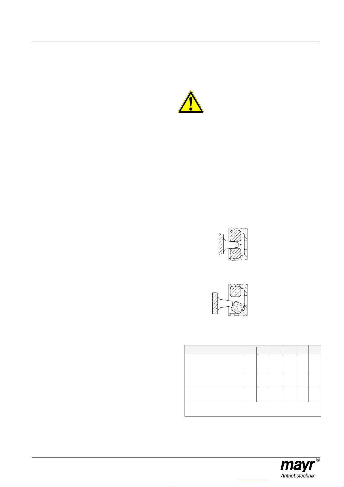
When joining the coupling halves, please make sure that the
claws are between and not on the rubber buffer, or the rubber
buffer may tilt (see Fig. 2). Also, please make sure that the
distance dimension “Z” is observed (see Table 1 or Fig. 1) when
joining the coupling halves, otherwise the permitted
misalignment possibilities become very limited.
Fig. 2
Table 1
Size 0 1 2 3 4 5
Tightening torque for
fixing screws
(Item 2.1, Fig. 1) [Nm]
5.5 5.5 9.5 23 46 80
Distance dimension „Z“
(Fig. 1) [mm]
4 4 4 4 4 4
Number of
rubber buffers 12 12 12 12 12 12
Temperature resistance
of rubber buffer +90 °C / -30 °C
Correct
Incorrect
Installation and Operational Instructions for
EAS®-lastic clutches Type 437._ _ _.0 (B.4.11.GB)
23/05/2006 K/TK/GC/RJ Chr. Mayr GmbH + Co. KG Tel.: 08341 / 804-0
Eichenstraße 1 Fax: 08341 / 804-421
87665 Mauerstetten http://www.mayr.de
Page 3 of 3 Germany eMail: info@mayr.de
Permitted Shaft Misalignment
The misalignment possibilities on the flexible coupling, shown in
Table 2, are maximum values. It is however important for a long
lifetime and smooth running that the alignment is as exact as
possible.
Fig. 3
Table 2
Size 0 1 2 3 4 5
x [mm] -1/+3 -1/+3 -1/+3 -1/+3 -1/+3 -1/+3
y [mm] 1 1 1 1 1 1
α
αα
α [°]
1 1 1111
Maintenance
The EAS®-clutch (1) has a grease filling and therefore requires no
greasing for the rest of its service lifetime. The axial backlash on
both clutch-supporting shafts should be inspected at regular
intervals. Too much bearing backlash can misalign the clutch axially.
This leads to changes in switching time and therefore to changes in
disengaging torque. Apart from this, the EAS®-clutch needs no
further maintenance.
Special maintenance is necessary should the device be subject to
very dirty, dusty or extreme ambient conditions. In this case, please
contact the manufacturers.
Disposal
Electronic Components
(Limit switch):
Products which have not been dismantled can be disposed of under
160214 (Mixed Materials) or Components under Code No.160216; or
the objects can be disposed of by a certified waste disposal firm.
All Steel Components:
Steel scrap (Code No. 160117)
Seals, O-rings, V-seals, elastomere, rubber buffers:
Plastics (Code No. 160119)
Malfunctions / Breakdowns
Malfunction Possible Causes
Disturbed running, bearings overheat during running Excessive axial pressure on the pressure flange; clutch is
incorrectly aligned.
Clutch does not disengage on overload Torque is set too high
Cup springs are layered wrongly
The axial pressure from the drive element is greater than the cup
spring pre-tension
Clutch disengages too quickly Torque is set too low
Large amount of wear on the ball or roller recesses
Clutch does not disengage on overload or disengages too late Incorrect limit switch setting
Switching element (1.1) constantly performs axial movements when
in operation Torque on clutch set too low
(Difference between operating torque and overload torque is too
small)
Torque peaks at low energy (Please contact the manufacturers)
y
x
α
α
α
α

Other Mayr Industrial Equipment manuals

Mayr ROBA-quick Quick start guide

Mayr

Mayr ROBA-quick Quick start guide

Mayr ROBA-stop-S User manual

Mayr

Mayr ROBA-stop-S User manual

Mayr ROBA -brake-checker plus User manual

Mayr

Mayr ROBA -brake-checker plus User manual

Mayr EAS-dutytorque 404 400 Series Quick start guide

Mayr

Mayr EAS-dutytorque 404 400 Series Quick start guide

Mayr EAS-HTL 4190. 5400 Series Quick start guide

Mayr

Mayr EAS-HTL 4190. 5400 Series Quick start guide

Mayr EAS-smartic 484.XX5 Series Quick start guide

Mayr

Mayr EAS-smartic 484.XX5 Series Quick start guide

Mayr EAS-Compact 49 Series Quick start guide

Mayr

Mayr EAS-Compact 49 Series Quick start guide

Mayr EAS-Compact 49 Series Quick start guide

Mayr

Mayr EAS-Compact 49 Series Quick start guide

Mayr ROBA-servostop 8981.29 01 Quick start guide

Mayr

Mayr ROBA-servostop 8981.29 01 Quick start guide

Mayr ROBA-spot-M 891 Series Quick start guide

Mayr

Mayr ROBA-spot-M 891 Series Quick start guide

Mayr ROBA-takt Quick start guide

Mayr

Mayr ROBA-takt Quick start guide

Mayr ROBA-stop-S 856 Quick start guide

Mayr

Mayr ROBA-stop-S 856 Quick start guide

Mayr EAS-NC User manual

Mayr

Mayr EAS-NC User manual

Mayr EAS-XT 475.24 Series Quick start guide

Mayr

Mayr EAS-XT 475.24 Series Quick start guide

Mayr ROBA-stop-stage Owner's manual

Mayr

Mayr ROBA-stop-stage Owner's manual

Mayr ROBATIC-clutch Quick start guide

Mayr

Mayr ROBATIC-clutch Quick start guide

Mayr ROBATIC 500.1 Series Quick start guide

Mayr

Mayr ROBATIC 500.1 Series Quick start guide

Mayr EAS-NC Quick start guide

Mayr

Mayr EAS-NC Quick start guide

Mayr ROBA-ES 94 Series Quick start guide

Mayr

Mayr ROBA-ES 94 Series Quick start guide

Mayr EAS-Compact Quick start guide

Mayr

Mayr EAS-Compact Quick start guide

Mayr ROBA-ES 940 Series Quick start guide

Mayr

Mayr ROBA-ES 940 Series Quick start guide

Mayr EAS-compact 493. 4 .0 Series User manual

Mayr

Mayr EAS-compact 493. 4 .0 Series User manual

Mayr EAS-Compact Type 49. 4. Size 4 Series Quick start guide

Mayr

Mayr EAS-Compact Type 49. 4. Size 4 Series Quick start guide

Mayr ROBA-stop 820.61 Series Quick start guide

Mayr

Mayr ROBA-stop 820.61 Series Quick start guide

Popular Industrial Equipment manuals by other brands

BIO UV UV3205HO Installation and maintenance manual

BIO UV

BIO UV UV3205HO Installation and maintenance manual

ProMinent ProMix Series operating instructions

ProMinent

ProMinent ProMix Series operating instructions

Trane Comfort Coil KIT06654 Installer's guide

Trane

Trane Comfort Coil KIT06654 Installer's guide

Fresmak ARNOLD 5XM Service manual

Fresmak

Fresmak ARNOLD 5XM Service manual

HydraMaster CrossFire 4.2 owner's manual

HydraMaster

HydraMaster CrossFire 4.2 owner's manual

Rothenberger THRED-O-MATIC 66-A Instructions for use

Rothenberger

Rothenberger THRED-O-MATIC 66-A Instructions for use

Fujitsu ScanSnap S300 Cleaning instructions

Fujitsu

Fujitsu ScanSnap S300 Cleaning instructions

ABB HT845109 Operation manual

ABB

ABB HT845109 Operation manual

Graco Therm-O-Flow 20 Instructions - parts

Graco

Graco Therm-O-Flow 20 Instructions - parts

ABB TPL69-A33 Series Operation manual

ABB

ABB TPL69-A33 Series Operation manual

MORLEY M48 owner's manual

MORLEY

MORLEY M48 owner's manual

BGU HRZ Kombi Anbau user manual

BGU

BGU HRZ Kombi Anbau user manual

RINGSPANN Brake HW 145 FHM Installation and operating instructions

RINGSPANN

RINGSPANN Brake HW 145 FHM Installation and operating instructions

Durlum LOOP TYPE 3 installation manual

Durlum

Durlum LOOP TYPE 3 installation manual

ABB HT842515 Operation manual

ABB

ABB HT842515 Operation manual

ATI Technologies 39-0214 quick start guide

ATI Technologies

ATI Technologies 39-0214 quick start guide

Siemens SIRIUS 3RT263-1 Series operating instructions

Siemens

Siemens SIRIUS 3RT263-1 Series operating instructions

Einhell Royal RHW 1100 Niro/Niro operating instructions

Einhell Royal

Einhell Royal RHW 1100 Niro/Niro operating instructions

manuals.online logo
manuals.online logoBrands
  • About & Mission
  • Contact us
  • Privacy Policy
  • Terms and Conditions

Copyright 2025 Manuals.Online. All Rights Reserved.