Tecnodue I.T.S. PT 355 User manual

I.T.S. by Tecnodue
PT 355
Edition 1208
Operating Manual

I.T.S. Ital Trade Service PT 355 Operating Manual
2
The technical data and information contained on this manual can be changed without any notice
I.T.S. Ital Trade Service PT 355 Operating Manual
3
PT 355
The machine has been designed and constructed for the welding of PE, PP, PVDF and other thermoplastics pipes and fittings.
I.T.S. Ital Trade Service S.r.l.
Via Scar ellini 77 , 16149 Genova Italy
Phone : +39-010-6423396
Fax : +39-010-6423513
E Mail : info@it -tecndoue.com
Web Site : www.it -tecnodue.com
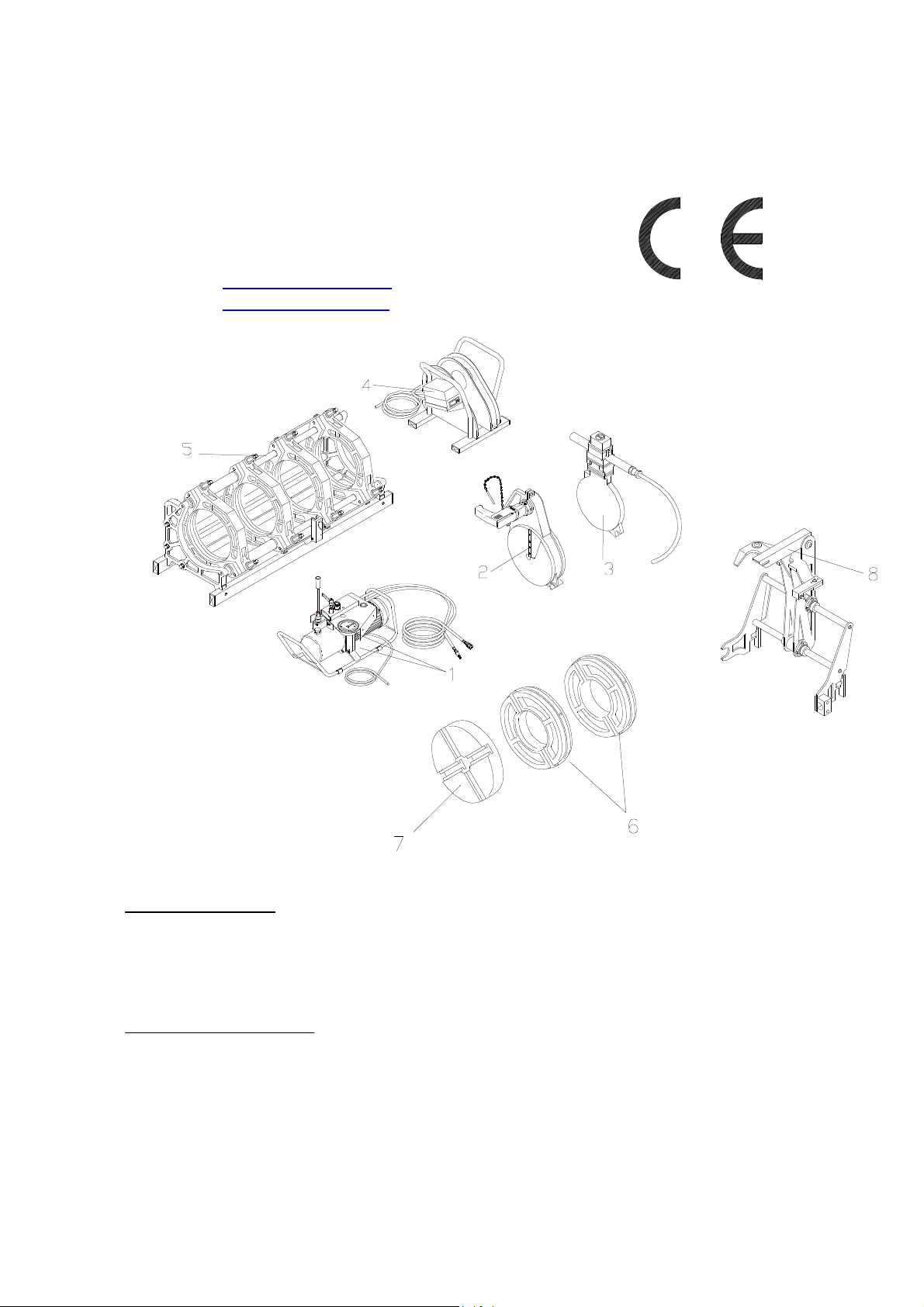
Standard Component
1. Hydraulic nit
2. Facing Tool
3. Heating Mirror
4. Support for facing tool and heating mirror
5. Basic machine
On reque t can be upplied:
6. Light weight alloy reducing rings for pipes and fittings d. 90,110,125,140,160,180,200,225,250,280,315mm
7. Stub End Device
8. MDD (PT automatic mirror device)
• Short spigot fittings clamp d. 355mm
• Wooden transport box according to ISPM 15
• LD (printing and storing data machine)
• Electric board with automatic circuit breaker
•
Rollers

I.T.S. Ital Trade Service PT 355 Operating Manual
4
SAFETY RULES ACCORDING TO DIRECTIVES CEE
( To be read carefully and apply while utilizing the PT 355 )
Due to the specific use, this machine cannot be supplied with all kind of fix and removable protections suitable to avoid any risk of accident.
The machine, therefore, must be utilized, adjusted and keep in the perfect functioning conditions by skill operators.
Warning - Rule – Obligation
The use of machines composed by electrical components and movable parts, it's always a potential danger. In order to avoid any kind of accident caused by
electrical or mechanical sources it' strongly suggested to read and follow carefully the following safety rules before operating the machine.
TRANSPORT
-.Basic Machine , Keep the maximum care while moving and it's suggested to utilize mechanical aids.
-.Facing Tool ,supplied with transport's hook.
Keep the maximum care while moving it and it's compulsory to utilize the handle also take care about the blades mounted in, it's compulsory use gloves.
-.Heating Mirror ,supplied with transport's handles
Keep the maximum care while moving it also keep the maximum care while utilizing it due to the high temperature involved always more than 200°C ,
it's strongly suggested to use suitable gloves.
In order to move from one working place to the other , the facing tool and the mirror must located into the special support , this support is heavy therefore
it's necessary to utilize the maximum care to move it
-.Hydraulic unit, supplied with transport's frame.
Keep the maximum care while moving it and in case utilize two person.
Avoid to transport the components by holding from the cable and remember to use suitable gloves.
ELECTRIC CONNECTIONS
The machine is operated by 230 Volts therefore be sure that the power supply plug is supplied with the safety devices according to the standard
requirements , also check that the power supply will be on the range of maximum 10% of the machine's nominal tension.
While the facing tool is connected to the power supply do not leave it into the basic machine but place it into the special support. In this position, even if the
start bottom is pushed the engine does not start.
Check regularly the cables and the plug and in case substitute by qualify personnel.
In case the heating mirror cable must be substitute the cable must be H07RN-F
Before carry out a reparation or maintenance all the plugs must with plug out from the power supply
ENVIRONMENTAL CONDITIONS
The working area must be clean and duly lighted. It's very dangerous to utilize the machine in case of rain or in wheat conditions or close to flammable agents.
CLOTHES
Keep the maximum care while utilizing the machine due to the high temperature involved on the heating mirror always more than 200°C , it's strongly
suggested to use suitable gloves. Avoid long clothes and avoid bracelets , necklaces that might be hooked into the machine.
CORRECT MACHINE'S OPERATION
Remember to check and read carefully the operating manual before utilizing the machine and the accessories.
KEEP ALWAYS THE MAXIMUN ATTENTION
After the heating mirror has been disconnected temperature will be hot for some minutes.
Keep the maximum care while utilizing the facing tool. Be careful to the blades , it's strongly suggested to use suitable gloves. During the facing operation
( facing tool in movement ) it's forbidden to take out the shavings
Avoid utilizing the machine after drinking or drugs use
Take care that all the people around the machine are at safety distance
While starting operating take care to avoid leave arms between the movable and fix trolleys.
SQUASHING DANGER
While starting operating take care to avoid leave legs or arms between the movable and fix trolleys. It's compulsory to be far from the basic machine
ACOUSTIC POLLUTION
The acoustic pollution of the drill engine is less than 85 dB ( value measured at 1 meter distance from the operator)
Due to some particular cases such as too much pressure during the facing the noise should be increased , therefore it's suggested to utilize some
protections.
IMPORTANT !!!!
Keep the maximum care reading and following the above Warning - Rules - Obligations the Ital Trade Services S.r.l. decline all responsibilities if are not
followed totally
Label on machine’ component
howing potential danger
WEAR BURNS ELECTRIC SQUASHING
GLOVES DANGER DANGER DANGER

I.T.S. Ital Trade Service PT 355 Operating Manual
5
1. Technical data
Operating data
Ambient temperature 0…50°C
Humidity (without condensation) 95 RH%
Transport and storing Temperature -10…60°C
Electrical data
Voltage 230 V
Frequency 50 Hz
Total power installed 5.13 KW 22.3 A
Heating mirror IP 54 3.24 KW
Facing tool IP 20 1.15 KW
Hydraulic unit IP 44 0.74 KW
Hydraulic data
Maximum working pressure 140 bar
Cylinder’s section 8,46 cm
2
Pressure gauge 0 - 160 bar
Pressure gauge precision class Cl. 1.0
Hydraulic unit engine revolutions 2800 rpm
Volumetric pump’s capacity 1,2 cc/rev.
Pump’s capacity 3.36 l/min
Hydraulic oil ISO 46
Oil tank’s capacity 1.5 liter
Mechanical Data
Facing tool transmission system Chain
Trolley maximum stroke 145 mm
Trolley slide bar diameter 35 mm
Distance between the cylinders centre 480 mm
Dimen ion
Basic machine 1125 x 680 x 640 mm
Facing tool 434 x 700 x 410 mm
Heating mirror 600 x 65 x 390 mm
Hydraulic unit 480 x 320 x 270 mm
Support for facing tool and heating mirror 500 x 450 x 500 mm
Weight
Basic machine 96 Kg
Facing tool 28 Kg
Heating mirror 19 Kg
Hydraulic unit 28 Kg
Support for facing tool and heating mirror 17 Kg
Wooden transport box 77 Kg
Stub end device 16 Kg
Reducing inserts complete set 79 Kg

I.T.S. Ital Trade Service PT 355 Operating Manual
6
2. General de cription and application field
Hydraulic operated butt welding machines suitable for PE,PP,PVDF and other thermoplastics pipes and fittings.
The self aligning frame and the compact dimensions make the machines highly suited for working in road constructions, ditches , aqueducts,
gas ducts , sewers and irrigation systems.
The machine is supplied complete of:
1) Basic machine d. 355 mm complete with a tools blue bag
2) Removable electric facing tool with safety switch
3) Removable PTFE coated heating mirror with a temperature control box.
4) Electro-hydraulic motor with accumulator and flexible hoses with quick couplings.
5) Support for facing tool and heating mirror
2.1 Ba ic machine
The basic machine is composed by:
• Two cylinders on which heads are mounted two complete
clamps d. 355 mm
• One movable clamp d.355 mm sliding on cylinder's stem and
fixable in different positions by means of using the clamps
connecting rods.
• A stiffening bar
• One side support clamp d.355 mm
• A frame including the hydraulic circuit with the anti-drop
quick couplings.
• A heating mirror disconnecting device
2.2 Facing Tool
The electric facing tool is composed by:
• The facing tool body
• Two disks where are mounted the blades
• A drill engine with a with a safety pin that , while connected keep the facing
tool hooked to the machine.
• A chain with a pin connected to a safety micro-switch allowing the engine
starts only when the facing tool is fit into the machine ,avoiding the start of
the engine out of this position.
2.3 Heating Mirror
The heating mirror is composed by:
• The heating mirror coated with green color PTFE complete with
thermometer (the thermometer does not depend upon the power supply and
always survey the real temperature of the heating plate) and connecting box
• The support suitable for the heating mirror and the facing tool
where is located the connecting box
• The electronic thermostat located on the connecting box .
• LD connector. (The below figure shows where the LD connector is
located ).
LD Connector
I.T.S. Ital Trade Service PT 355 Operating Manual
7
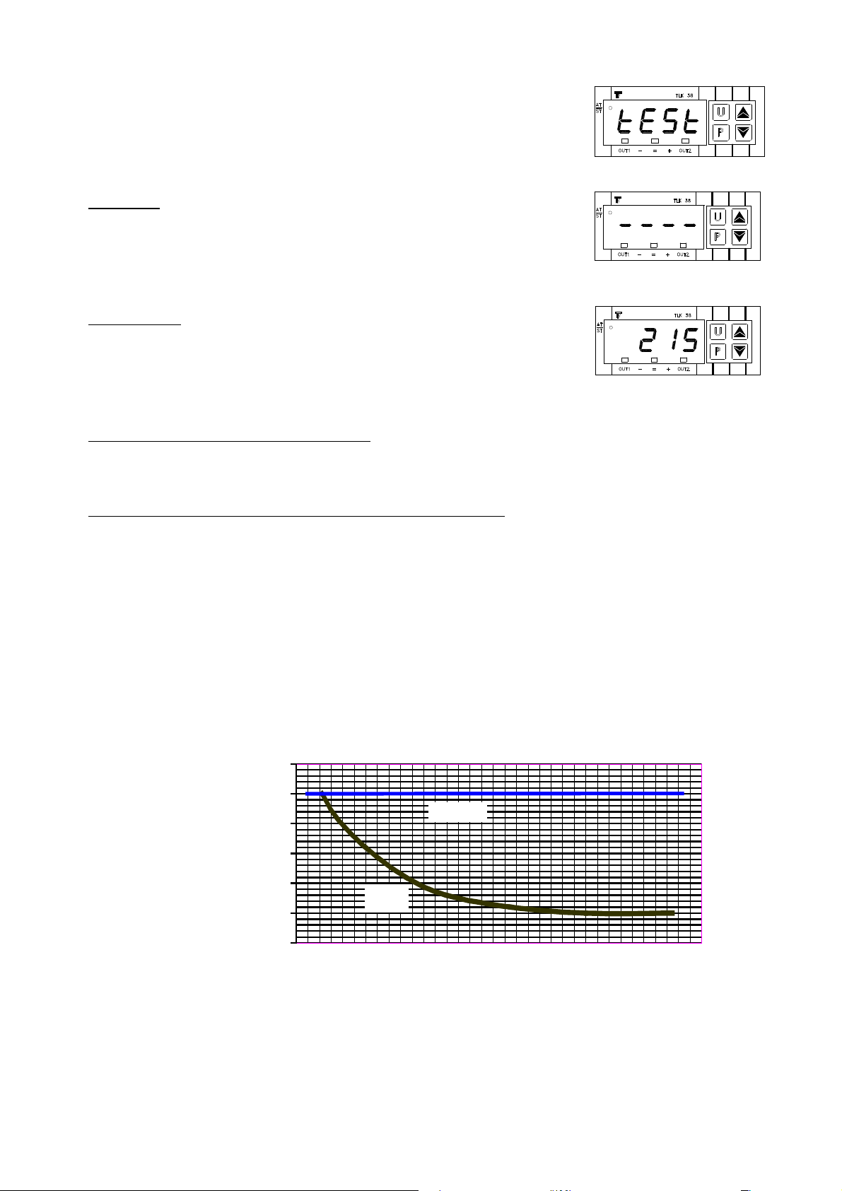
2.3.1 Electronic thermo tat – different function
At each startup on the display will blink the writing ‘TEST’. This means that the
thermostat is testing the connection between the probe and the heating mirror.
If the test fails, the display will show 4 blinking upper scores (as per figure aside),
in this case the probe or the connection between the thermostat and the heating
mirror could be interrupted.
If the test success, the display will show the real temperature of the heating mirror and the
heating mirror warms up (the O T1 red led is switched on) until the set point value (the selected
temperature) has been achieved (central green light led).
To display the actual set point value of the temperature stored by the thermostat, push the key P. The display will show alternately the
writing ‘SP1’ and the et point value of the temperature. After 5 seconds the display will show again the real value of the heating
mirror temperature
To select a new value for the thermostat set point value (default value = 220°C):
1. Push the key P (The display will show alternately the writing ‘SP1’ and the et point value of the temperature)
2. By acting on the arrow keys P and DOWN it is possibile to increase or decrease the set point value.
3. When you reach the desired value push the key P to confirm.
4. The display will show again the real value of the heating mirror temperature
5. When the heating mirror will reach the set point value on the display the central green light led will be switched on.
Warning: On the thermo tat di play i alway hown the actual value of the heating mirror temperature (and never the et
point value!)
Temperature of the welding mirror for welding PE DVS 2207-1 norm
195
200
205
210
215
220
225
0 10 20 30 40 50 60 70
pipe wall thickne (mm)
Mirror temperature (°C)
PE100
PE80
0
Remember
W
hen welding PVDF, the temperature of the welding mirror should be adjusted for every wall thickness at 240°C +/- 8°C
When welding PP, the temperature of the welding mirror should be adjusted for every wall thickness at 210°C +/-10°C

I.T.S. Ital Trade Service PT 355 Operating Manual
8
2.4 Hydraulic Unit
The basic components of the hydraulic unit are the following:
• Electric engine
• Hydraulic pump
• Oil tank
• Hydraulic unit controls
• Pressure accumulator
• Pressure gauge
• Metal frame
2. 4.1 Hydraulic Unit Control
The control lever A open and close the machine's trolley according to the
position selected.
Bring the lever A into position A2 (position with automatic return) the trolley
is opening with the maximum pressure set up into the hydraulic unit
In position A1 the lever shut down automatically the engine ( release position ).
Bring the lever A into the position A3 ( position with hooking) the trolley is
closing, the hooking of such position allow the operator handling.
The hand wheel F of the pressure control allow the setting up of the
pressure at the requested values by turning anti clockwise the
pressure release , while turning clockwise the pressure increase .
The pressure by pass lever E allow ,by turning anti clockwise the
pressure releasing , while turning clockwise allow the pressure
increasing by means of using the hand wheel F and fixing. If you
completely clockwise turn the by pass valve, the pressure will be
blocked and the hydraulic unit will maintain the same pressure in case
of engine switched off.

I.T.S. Ital Trade Service PT 355 Operating Manual
9
2.4.2 How to u e the hydraulic unit
Operating In truction
In order to make easy the learning we shall proceed to the description step
by step of all operations need in order to complete a welding according to
the following description:
Important !
Before begin the following operation be sure that:
- The lever A is fixed into the special housing
- Substitute the metal plug with the plastic black and red plug the
plastic plug is supplied with the machine into a plastic bag.
01. Fit the two pipes to be weld ( see relative instructions )
02. By turning the lever E anticlockwise bring the pressure to zero,
checking the pressure gauge D
03. Turn clockwise the lever E until closing ( please avoid using an
excessive strength )
04. Bring the lever A into position A3
05. By turning clockwise the hand wheel F achieve the inertial pressure
value ( value of pressure need in order to allow the trolley moving )
note the value of inertial pressure read into the pressure gauge D,
then by still operating the hand wheel F , increase the inertial pressure
value by the welding theoretical pressure value as per attached table.
06. Achieved the true welding pressure value ( inertial pressure plus
theoretical welding pressure ) bring the lever A into position A2.
07. Fit the facing tool (see relative instructions )
08. By acting on lever E anticlockwise achieve a pressure value of approx 5 bar more than the inertial pressure value checked and
then proceed to the facing tool operation (taking care that the engine's overloading).
09. At the end of the facing operation bring the lever A into position A3 and remove the facing tool.
10. Fit the heating mirror taking care that the temperature of the surfaces is the one selected (see relative instructions)
11. Bring the lever A into A3 in order to have the bead formation as per attached table, this operation must be done with the true
welding pressure value.
12. After bead formation act on lever E anticlockwise in order to bring the pressure to zero and proceed to the heating time as per
attached table.
13. Elapsed the heating time at pressure zero bring the lever A into position A2 and remove the heating mirror and immediately
bring the lever A into position A3 and acting on lever E clockwise put in contact the two pipes until achieving the true welding
pressure value by checking the pressure gauge D. These operations must be done according to the time indicated into the
attached table.
14. Bring the lever A into position A1 and keep such situation for all the cooling time indicated into the attached table, taking care
that the pressure will not decrease too much, in case bring for a little while the lever A into position A3 and put back into position A1
15. Elapsed the cooling time by acting on lever E anticlockwise bring the pressure to zero.
16. Take away the pipes welded
WE STRONGLY SUGGEST TO TRY MANY TIMES AND GET FAMILIAR TO THE UNIT BEFORE CARRYING ON WITH COMPLETE WELDING.
A WRONG USE OF THE HYDRAULIC UNIT COULD COMPROMISE YOUR WELDINGS..

I.T.S. Ital Trade Service PT 355 Operating Manual
10
3. Heating mirror di connecting device
You can configure the machine according to the kind of welding to be executed as per the following different ways:
• Two fixed clamps and two moveable clamps Fig. 1
• One fixed clamp and three moveable clamps Fig. 2
You can change from a configuration to another in a quick way by simply acting on the two spacers and on the disconnecting device.
In the first configuration of the machine the disconnecting devices is between the two moveable clamps and the two fixed clamps.
The spacers are between the two fixed clamps.
In the second configuration of the machine the disconnecting devices is between the three moveable clamps and the fixed clamp.
The spacers are between the second and third moveable clamps.
Figure 1.Configuration 2 moveable clamp + 2 fixed clamp Figure 2. Configuration 3 moveable clamp + 1 fixed clamp
Figure 3.
On the left:
You can modify the distance between the clamps connected by the spacers.
Fix the first clamp to the hole A and the second clamp in one of the holes B,C,D,E
On the right (from above) pper and lower spacer (interchangeable) and
disconnecting device
WARNING !
Only in two confirguration you can u e the di connecting device with pacer ! In the other configuration u e only the pacer to
avoid eriou damage to the ba ic machine!
I.T.S. Ital Trade Service PT 355 Operating Manual
11
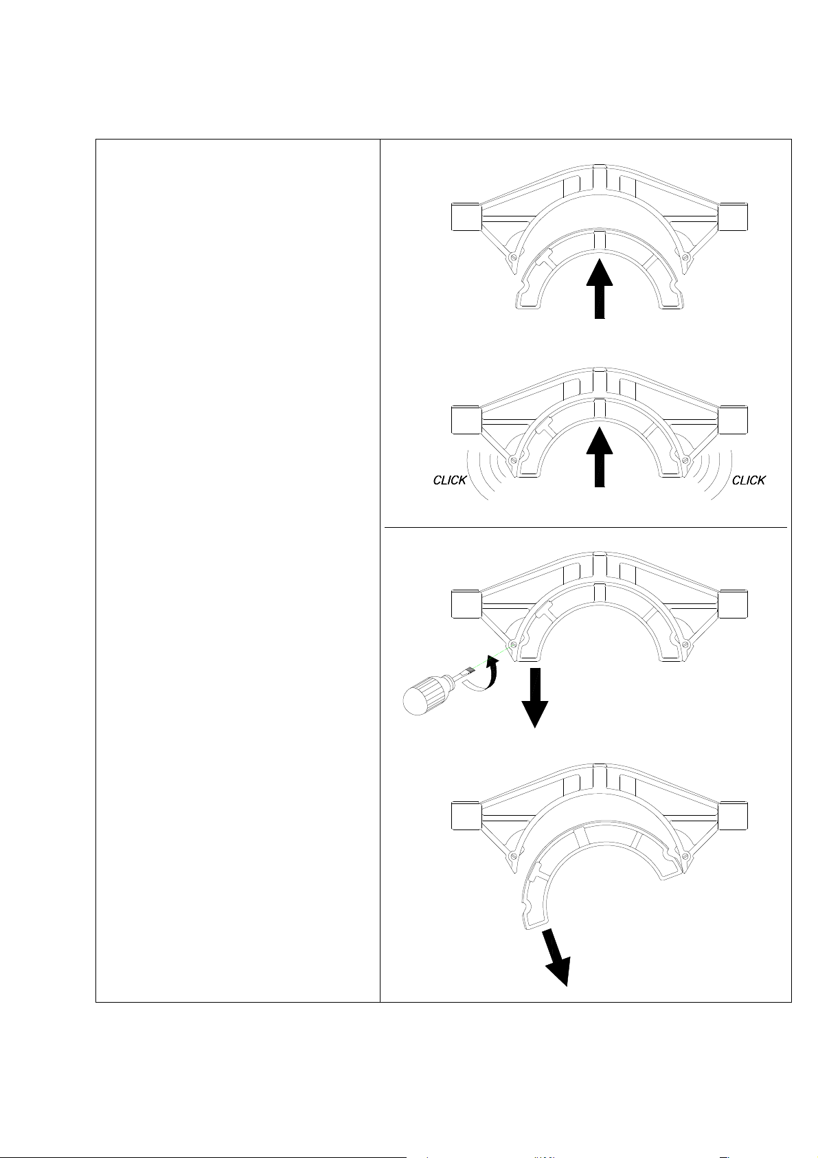
3.1 Beep-beep in ert reduction
To u e a beep-beep in ert reduction
To use a beep-beep reduction, fix it by lightly pushing
the reduction in the direction shown as per figure
aside. As you hear a ‘click’ sound the reduction is
properly fixed.
To remove the beep-beep reduction
To safely remove the beep-beep reduction by means
of a screwdriver turn to left the screw shown in the
figure aside. As soon as the reduction is not anymore
hooked to the clamp you can remove it.
Attention: If you need to u e reduction under d. 250mm you mu t before in tall the reduction d.
355x250mm
I.T.S. Ital Trade Service PT 355 Operating Manual
12
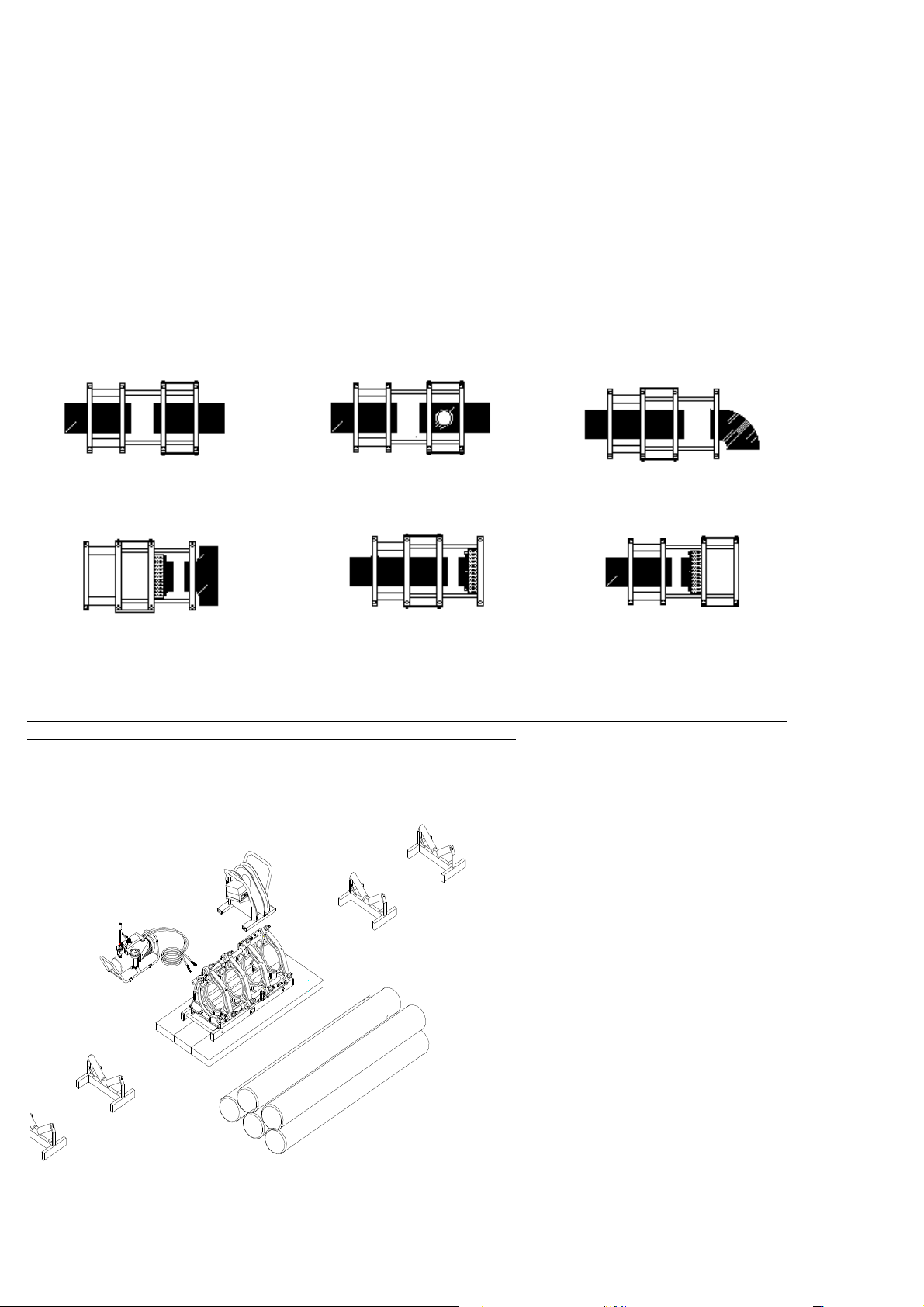
4. Butt welding in brief
4.1 Introduction
Stated that the basic machine it's suitable for all kinds of pipe, fittings and stub end available on the nowadays market. Here follows all the
different welding configurations of the machine:
1) Pipe with Pipe, standard configuration of the machine
2) Pipe with long spigot fitting, standard configuration of the machine
3) Pipe with short spigot fitting, to achieve this kind of welding it is strongly suggested to configure the machine with three moveable
clamps and 1 fixed clamp. Furthermore you must use the upper fittings clamp to fix better the fittings to the fixed clamp
4) Fitting with short spigot stub end, to achieve this kind of welding it is strongly suggested to configure the machine with three
moveable clamps and 1 fixed clamp. To fix the stub end you must use a special accessory called stub end device. Place the 4
brackets at the appropriate size punched on the stub end device. Fix the stub end by tighten the bolt of each bracket. The stub
end device is supplied with a fixing ring and you can install it on each clamp of the machine.
5) Pipe with short spigot stub end, to achieve this kind of welding you can use two different configuration of the machine (5 or 6)
6) Pipe with short spigot stub end, to achieve this kind of welding you can use two different configuration of the machine (5 or 6)
1. PIPE WITH PIPE 2. PIPE WITH LONG SPIGOT FITTING
3. PIPE WITH SHORT SPIGOT FITTING
4. FITTING WITH SHORT SPIGOT STUB END 5. PIPE WITH SHORT SPIGOT STUB END 6. PIPE WITH SHORT SPIGOT STUB END
4.2 Machine' preparation
It' trongly ugge ted to u e pipe roller for the liding of the pipe to be welded and if it' po ible po itioning the machine
with wooden table below, uch care will avoid additional effort to the machine.
a) Set up the working area so that welding is protected from the weather. Position the machine's components as per following figure
and eventually utilize wooden panels
b) Connect the flexible hoses of the hydraulic unit to the machine

I.T.S. Ital Trade Service PT 355 Operating Manual
13
c) Connect the plugs to the power supply (Hydraulic unit, Facing tool and Heating mirror) after checking that the main power
supply is within a 10% of the specified one “ Warning Heating Mirror tart to warm up ! “
d) Select the correct temperature on the heating mirror
e) In case fit the inserts of the diameter to be welded into the machine
4.3 Pipe po itioning into the machine and facing operation
a) Open the movable trolley of the machine by means of acting the lever A (hyd. Unit) and take it in position A2
b) Position the pipes into the machine taking care to leave enough space for the facing tool inserting
c) Check the pipes alignment, in case adjust it by means of tighten or loosing the clamps bolts. The maximum misalignment could be lesser
than 10% of the pipe or fittings wall thickness. In any case the misalignment cannot be over than 2mm.
d) Clean the pipe ends
e) Fit in the facing tool between the two pipe's ends to be faced, by means of connecting the facing tool into the special supports. Connect
the safety pin and start the facing tool engine
Warning!!!: Alway check that the peed elector of the drill engine i in po ition 1 (lower peed)
f) Slowly approach the pipes ends towards the facing tool by means of acting on the hydraulic control unit (lever A Table V ) keeping
a value of pressure allowing the facing of the surfaces and avoiding an overload of the drill engine (a too much high pressure could
burnt out the drill engine). When shavings from both sides will appear continuous and homogeneous , the facing operation is
completed.
g) Put in contact the two pipes ends to be welded and check if the eventual disjunction is within the values of the following table:
In case the above values cannot be fulfilled the facing operation must be repeat.
4.4 Inertial pre ure mea urement
Before begin a welding cycle it is necessary to measure the inertial pressure. This value must be added to the pressure value shown in our
welding tables. The inertial pressure value depends on welding operating conditions (ex.: length and weight of the pipe to drag, general
condition of the machine, ambient temperature, etc.). To measure the inertial pressure follow these steps:
a) Completely open the movable trolley of the machine by means of acting the lever A and take it in position A2
b) By turning the lever F (Hyd. Unit) anticlockwise bring the pressure to zero, checking the pressure gauge
c) Turn clockwise the lever E (Hyd. Unit) until closing
d) Bring the lever A (Hyd. Unit) into position A3 (the trolleys do not move because there is no pressure)
e) By turning clockwise the hand wheel F note the inertial pressure value ( value of pressure need in order to allow the trolley moving ) by
reading it into the pressure gauge
Out ide diameter
mm
Port
mm
< 400 0,5
> 400 1,0
I.T.S. Ital Trade Service PT 355 Operating Manual
14
4.5 Welding cycle
To obtain the be t re ult we trongly ugge t allowing the u e of the machine only to experienced operator
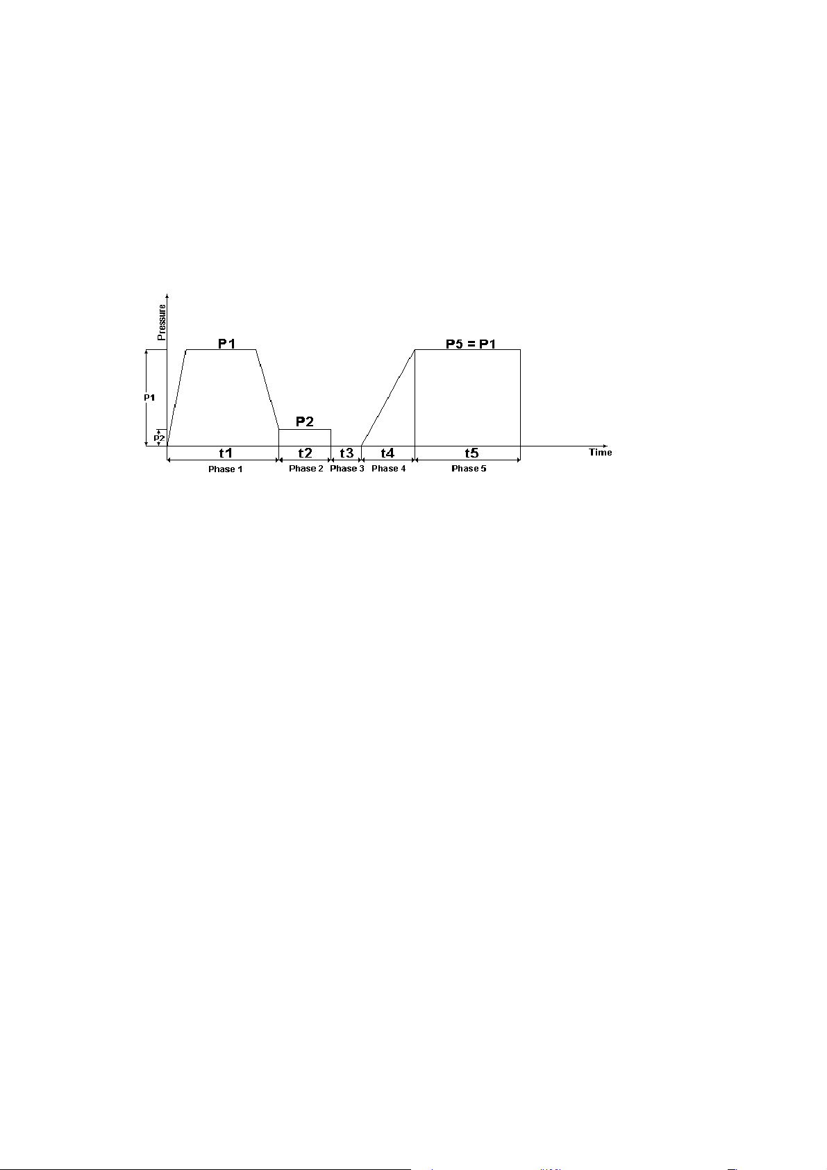
The welding phase is composed by 5 phases with 5 different times:
PHASE 1 = t1 = Time requested for the bead formation with the specified wall thickness
PHASE 2 = t2 = Time requested for the continual heating
PHASE 3 = t3 = Time requested for the change over
PHASE 4 = t4 = Time requested for bringing up the pressure
PHASE 5 = t5 = time requested for cooling down
Pre ure-Time diagram for butt welding
PHASE 1 = Heating up t1
a) Fit the heating mirror taking care that the temperature of the surfaces is the one selected
b) Bring the lever A (Hyd. Unit) into position A3 in order to have the bead formation as per attached table, this operation must be done
with the true welding pressure value: ( Inertial pressure + P1 ).
c) Check the Bead formation wall thickness according to the attached welding table
PHASE 2 = Heating up t2
a) After bead formation act on lever E (Hyd. Unit) anticlockwise in order to bring the pressure nearly to zero and proceed to the heating
time t2 at pressure P2
PHASE 3 = Change over t3
a) Elapsed the heating time at pressure P2 bring the lever A (Hyd. unit) into position A2 and remove the heating mirror and immediately
bring the lever A into position A3 and acting on lever E clockwise put in contact the two pipes
PHASE 4 = Bringing up pre ure t4
a) Achieve the true welding pressure value: (Inertial pressure + P1 = P5 ) by checking the pressure gauge, This operation must be done
according to the time indicated into the attached welding table.
PHASE 5 = Cooling Down t5
a) Bring the lever A into position A1 and keep such situation for all the cooling time indicated into the attached welding table, taking care
that the pressure will not decrease too much
b) Elapsed the cooling time by acting on lever E anticlockwise bring the pressure to zero.
c) Take away the pipes welded
Important !!!
In case of any doubt please refer to the specific instructions
I.T.S. Ital Trade Service PT 355 Operating Manual
15
5. Welding Parameter for PE pipe & fitting DVS norm ver ion 2207-1
Pre ure-Time diagram for butt welding
t1 = Time requested for the bead formation with the specified wall thickness
t2 = Time requested for the continual heating
t3 = Time requested for the change over
t4 = Time requested for bringing up the pressure
t5 = time requested for cooling down
P1 = Pressure during the bead formation and the cooling down, this value is the result of the formula:
Pipe ection( cm2 ) x Material thru t coefficient( Kg./cm2 )
____________________________________________________________ = bar
Total machine cylinder ection( cm2 )
Material thrust coefficient for PE s 63 1,5 Kg./cm2
Material thrust coefficient for PP 1,0 Kg./cm2
Total PT 160 cylinders section 4,32 cm2
P2 = Pressure during the continual heating, this value either for HDPE and PP is 0,1 Kg./cm2.
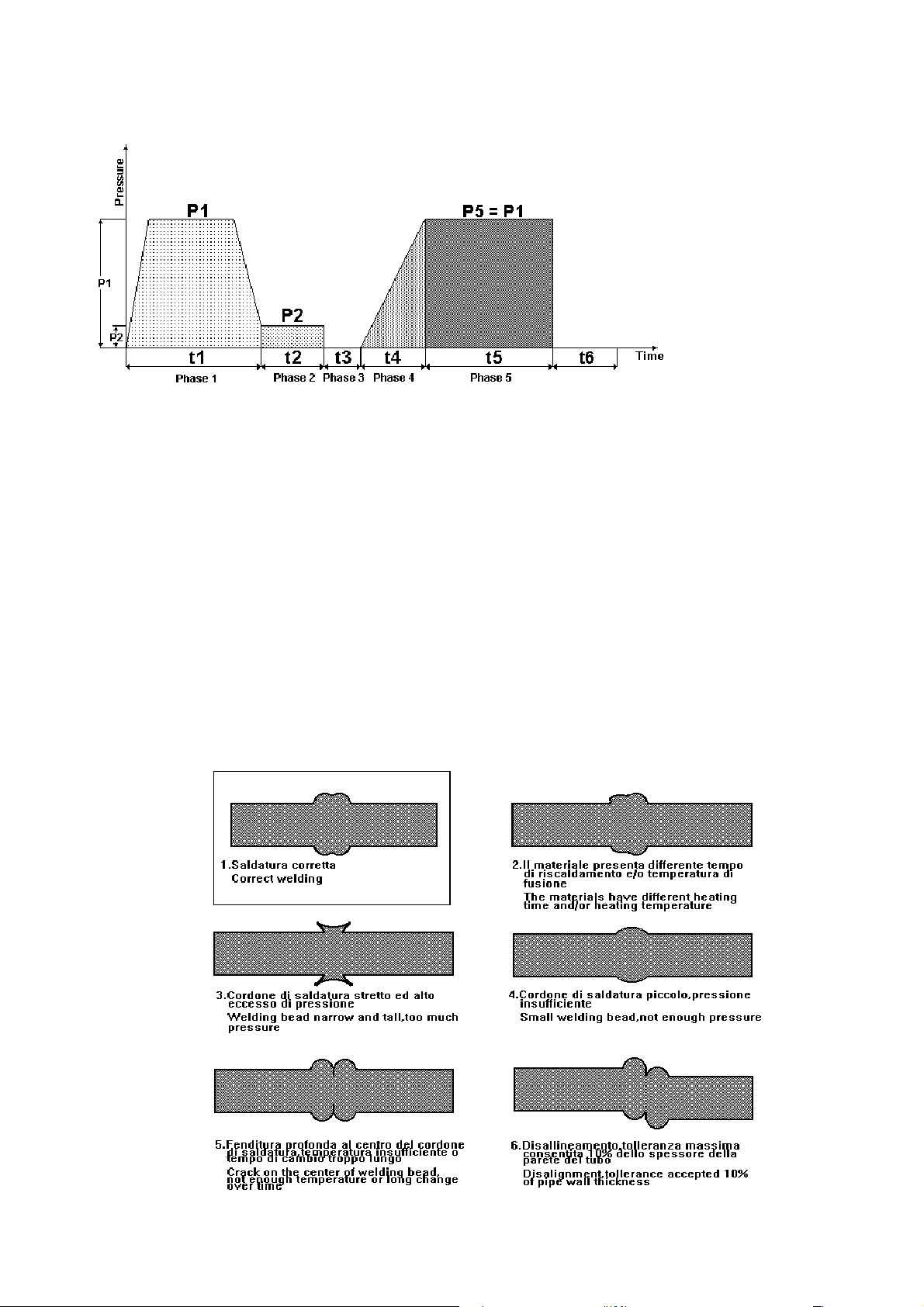
Optical
checking of butt welding re ult

I.T.S. Ital Trade Service PT 355 Operating Manual
16
5.1
Welding Parameter for PE & PP heet ,pipe & fitting according to DVS 2207-1 – 2207-11
Nominal Wall thickness
mm
Alignment
Bead height on heater
plate at the end of the
alignment time (alignment
under 0.15 N/mm
2
)
mm (minimum values)
Heating-up
Heating-up time= 10 x
wallthickness (heating-
up 0.02 N/mm
2
)
s
Changeover time
S (maximum time)
Joining pressure
s
Cooling time under
joining pressure p=0.15
N/mm2 0.01
Min (minimum values)
MATERIAL PE
ntil 4.5 0.5 45 5 5 6
4.5 … 7 1.0 45 … 70 5 … 6 5 … 6 6 … 10
7 … 12 1.5 70 … 120 6 … 8 6 … 8 10 … 16
12 … 19 2.0 120 … 190 8 … 10 8 … 11 16 … 24
19 … 26 2.5 190 … 260 10 … 12 11 … 14 24 … 32
26 … 37 3.0 260 … 370 12 ... 16 14 … 19 32 … 45
37 … 50 3.5 370 … 500 16 … 20 19 … 25 45 … 60
50 ... 70 4.0 500 … 700 20 … 25 25 … 35 60 … 80
MATERIAL PP
ntil 4.5 0.5 135 5 6 6
4.5 … 7 0.5 135 … 175 5 … 6 6 … 7 6 … 12
7 … 12 1.0 175 … 245 6 … 7 6 … 11 12 … 20
12 … 19 1.0 245 … 330 7 … 9 11 … 17 20 … 30
19 … 26 1.5 330 … 400 9 … 11 17 … 22 30 … 40
26 … 37 2.0 400 … 485 11 ... 14 22 … 32 40 … 55
37 … 50 2.5 485 … 560 14 … 17 32 … 43 55 … 70
Example on how to calculate the cooling down (t5) time following the DVS NORM
As per drawing above the time T corresponds to wall thickness value X in
mm. To calculate this time (t5 in minutes) please follow the formula below:
Example:
If you want to calculate the cooling down time for a 6mm wall thickness pipe, you must simply substitute the variable X with the value 6:
min,),(
,
T48546
547
6
10
6=−⋅
−
−
+=
To calculate the other times (t3 and t4) you must use the same principle of linear interpolation.
To obtain the t2 (in seconds) value use the formula below where the variable wt corresponds to the nominal wall thickness
)
mm
(
wt
(sec)
T
⋅
=
10
2
)5,4(
5,47 610
6−⋅
−
−
+= xT

I.T.S. Ital Trade Service PT 355 Operating Manual
17
6. Welding Table for PE pipe DVS norm ver ion 2207-1
The following tables show the values to be applied during the welding cycle as per previous instructions and graph.
However in order to clarify once again the meaning of these values please kindly note:
t1 = Time requested for the bead formation to be done with pressure value = P1 + inertial pressure
t2 = Time requested for the continual heating to be done with pressure value = P2 + inertial pressure
t3 = Time requested for the change over
t4 = Time requested for bringing up the pressure at the value of pressure = P1 + inertial pressure
t5 = time requested for cooling down to be done with pressure value = P1 + inertial pressure
Important
Remember alway to add the value checked of inertial pre ure to the P1 and P2 value !!!!!!!
PT 355 - DVS 2207-1
Cyl. section cm
2
8,46
Welding range 90-355 mm
material PE80-100 SDR 41
D S T P1 bead P2 t 2 t 3 t 4 P5 t 5
DIAMETER WALL THICK. TEMP. BEAD FORMATION HEATING UP CHANGEOV.
RAMP COOLING
mm mm °C bar mm bar sec sec sec bar min
90 2,2 220 1,1 0,5 0..
0,1 22 0.. 5
5 1,1 6
110 2,7 220 1,6 0,5 0..
0,1 27 0.. 5
5 1,6 6
125 3,0 220 2,1 0,5 0..
0,1 30 0.. 5
5 2,1 6
140 3,4 220 2,6 0,5 0..
0,2 34 0.. 5
5 2,6 6
160 3,9 220 3,4 0,5 0..
0,2 39 0.. 5
5 3,4 6
180 4,4 220 4,3 0,5 0..
0,3 44 0.. 5
5 4,3 6
200 4,9 219 5,3 1,0 0..
0,4 49 0.. 5
5 5,3 7
225 5,5 218 6,7 1,0 0..
0,4 55 0.. 5
5 6,7 8
250 6,1 217 8,3 1,0 0..
0,6 61 0.. 6
6 8,3 9
280 6,8 216 10,4
1,0 0..
0,7 68 0.. 6
6 10,4 10
315 7,7 215 13,1
1,5 0..
0,9 77 0.. 6
6 13,1 11
355 8,7 214 16,7
1,5 0..
1,1 87 0.. 7
7 16,7 12
PT 355 - DVS 2207-1
Cyl. section cm
2
8,46
Welding range 90-355 mm
material PE80-100 SDR 33
D S T P1 bead P2 t 2 t 3 t 4 P5 t 5
DIAMETER WALL THICK. TEMP. BEAD FORMATION HEATING UP CHANGEOV.
RAMP COOLING
mm mm °C bar mm bar sec sec sec bar min
90 2,7 220 1,3 0,5 0..
0,1 27 0.. 5
5 1,3 6
110 3,3 220 2, 0,5 0..
0,1 33 0.. 5
5 2, 6
125 3,8 220 2,6 0,5 0..
0,2 38 0.. 5
5 2,6 6
140 4,2 220 3,2 0,5 0..
0,2 42 0.. 5
5 3,2 6
160 4,8 219 4,2 1,0 0..
0,3 48 0.. 5
5 4,2 7
180 5,5 218 5,3 1,0 0..
0,4 55 0.. 5
5 5,3 8
200 6,1 218 6,5 1,0 0..
0,4 61 0.. 6
6 6,5 8
225 6,8 216 8,3 1,0 0..
0,6 68 0.. 6
6 8,3 10
250 7,6 215 10,2
1,5 0..
0,7 76 0.. 6
6 10,2 11
280 8,5 215 12,8
1,5 0..
0,9 85 0.. 7
7 12,8 12
315 9,5 213 16,2
1,5 0..
1,1 95 0.. 7
7 16,2 13
355 10,8 212 20,6
1,5 0..
1,4 108 0.. 8
8 20,6 15
Warning!: in case of PE100 welding, temperature T must be increased to 220°c

I.T.S. Ital Trade Service PT 355 Operating Manual
18
PT 355 - DVS 2207-1
Cyl. section cm
2
8,46
Welding range 90-315 mm
material PE80-100 SDR 27,6
D S T P1 bead P2 t 2 t 3 t 4 P5 t 5
DIAMETER WALL THICK. TEMP. BEAD FORMATION HEATING UP CHANGEOV.
RAMP COOLING
mm mm °C bar mm bar sec sec sec bar min
90 3,3 220 1,6 0,5 0..
0,1 33 0.. 5
5 1,6 6
110 4,0 220 2,4 0,5 0..
0,2 40 0.. 5
5 2,4 6
125 4,5 220 3, 1,0 0..
0,2 45 0.. 5
5 3, 6
140 5,1 219 3,8 1,0 0..
0,3 51 0.. 5
5 3,8 7
160 5,8 218 5, 1,0 0..
0,3 58 0.. 6
6 5, 8
180 6,5 217 6,3 1,0 0..
0,4 65 0.. 6
6 6,3 9
200 7,2 216 7,8 1,5 0..
0,5 72 0.. 6
6 7,8 10
225 8,2 215 9,8 1,5 0..
0,7 82 0.. 6
6 9,8 11
250 9,1 214 12,2
1,5 0..
0,8 91 0.. 7
7 12,2 12
280 10,1 213 15,2
1,5 0..
1,0 101 0.. 7
7 15,2 14
315 11,4 212 19,3
1,5 0..
1,3 114 0.. 8
8 19,3 15
355 12,9 210 24,5
2,0 0..
1,6 129 0.. 8
8 24,5 17
PT 355 - DVS 2207-1
Cyl. section cm
2
8,46
Welding range 90-355 mm
material PE80-100 SDR 26
D S T P1 bead P2 t 2 t 3 t 4 P5 t 5
DIAMETER WALL THICK. TEMP. BEAD FORMATION HEATING UP CHANGEOV.
RAMP COOLING
mm mm °C bar mm bar sec sec sec bar min
90 3,5 220 1,7 0,5 0..
0,1 35 0.. 5
5 1,7 6
110 4,2 220 2,5 0,5 0..
0,2 42 0.. 5
5 2,5 6
125 4,8 220 3,2 1,0 0..
0,2 48 0.. 5
5 3,2 6
140 5,4 219 4, 1,0 0..
0,3 54 0.. 5
5 4, 7
160 6,2 217 5,3 1,0 0..
0,4 62 0.. 6
6 5,3 9
180 6,9 216 6,7 1,0 0..
0,4 69 0.. 6
6 6,7 10
200 7,7 215 8,2 1,5 0..
0,5 77 0.. 6
6 8,2 11
225 8,7 214 10,4
1,5 0..
0,7 87 0.. 7
7 10,4 12
250 9,6 213 12,9
1,5 0..
0,9 96 0.. 7
7 12,9 13
280 10,8 212 16,1
1,5 0..
1,1 108 0.. 8
8 16,1 15
315 12,1 211 20,4
2,0 0..
1,4 121 0.. 8
8 20,4 16
355 13,7 210 25,9
2,0 0..
1,7 137 0.. 8
9 25,9 18
PT 355 - DVS 2207-1
Cyl. section cm
2
8,46
Welding range 90-355 mm
material PE80-100 SDR 22
D S T P1 bead P2 t 2 t 3 t 4 P5 t 5
DIAMETER WALL THICK. TEMP. BEAD FORMATION HEATING UP CHANGEOV.
RAMP COOLING
mm mm °C bar mm bar sec sec sec bar min
90 4,1 220 2, 0,5 0..
0,1 41 0.. 5
5 2, 6
110 5,0 219 2,9 1,0 0..
0,2 50 0.. 5
5 2,9 7
125 5,7 218 3,8 1,0 0..
0,3 57 0.. 5
5 3,8 8
140 6,4 217 4,7 1,0 0..
0,3 64 0.. 6
6 4,7 9
160 7,3 216 6,2 1,5 0..
0,4 73 0.. 6
6 6,2 10
180 8,2 215 7,8 1,5 0..
0,5 82 0.. 6
6 7,8 11
200 9,1 214 9,7 1,5 0..
0,6 91 0.. 7
7 9,7 13
225 10,2 213 12,2
1,5 0..
0,8 102 0.. 7
7 12,2 14
250 11,4 212 15,1
1,5 0..
1,0 114 0.. 8
8 15,1 15
280 12,7 210 18,9
2,0 0..
1,3 127 0.. 8
8 18,9 17
315 14,3 209 24, 2,0 0..
1,6 143 0.. 9
9 24, 19
355 16,1 208 30,4
2,0 0..
2,0 161 0.. 9
10 30,4 21
Warning!: in case of PE100 welding, temperature T must be increased to 220°c

I.T.S. Ital Trade Service PT 355 Operating Manual
19
PT 355 - DVS 2207-1
Cyl. section cm
2
8,46
Welding range 90-355 mm
material PE80-100 SDR 21
D S T P1 bead P2 t 2 t 3 t 4 P5 t 5
DIAMETER WALL THICK. TEMP. BEAD FORMATION HEATING UP CHANGEOV.
RAMP COOLING
mm mm °C bar mm bar sec sec sec bar min
90 4,3 220 2, 0,5 0..
0,1 43 0.. 5
5 2, 6
110 5,2 219 3,1 1,0 0..
0,2 52 0.. 5
5 3,1 7
125 6,0 218 3,9 1,0 0..
0,3 60 0.. 6
6 3,9 8
140 6,7 217 4,9 1,0 0..
0,3 67 0.. 6
6 4,9 9
160 7,6 215 6,5 1,5 0..
0,4 76 0.. 6
6 6,5 11
180 8,6 214 8,2 1,5 0..
0,5 86 0.. 7
7 8,2 12
200 9,5 213 10,1
1,5 0..
0,7 95 0.. 7
7 10,1 13
225 10,7 212 12,8
1,5 0..
0,9 107 0.. 7
7 12,8 14
250 11,9 211 15,8
1,5 0..
1,1 119 0.. 8
8 15,8 16
280 13,3 210 19,8
2,0 0..
1,3 133 0.. 8
9 19,8 18
315 15,0 209 25,1
2,0 0..
1,7 150 0.. 9
9 25,1 19
355 16,9 208 31,8
2,0 0..
2,1 169 0.. 9
10 31,8 22
PT 355 - DVS 2207-1
Cyl. section cm
2
8,46
Welding range 90-355 mm
material PE80-100 SDR 17,6
D S T P1 bead P2 t 2 t 3 t 4 P5 t 5
DIAMETER WALL THICK. TEMP. BEAD FORMATION HEATING UP CHANGEOV. RAMP COOLING
mm mm °C bar mm bar sec sec sec bar min
90 5,1 219 2,4 1,0 0..
0,2
51 0.. 5 5 2,4 7
110 6,3 217 3,6 1,0 0..
0,2
63 0.. 6 6 3,6 9
125 7,1 216 4,7 1,5 0..
0,3
71 0.. 6 6 4,7 10
140 8,0 215 5,8 1,5 0..
0,4
80 0.. 6 6 5,8 11
160 9,1 214 7,6 1,5 0..
0,5
91 0.. 7 7 7,6 13
180 10,2 213 9,7 1,5 0..
0,6
102 0.. 7 7 9,7 14
200 11,4 212 11,9
1,5 0..
0,8
114 0.. 8 8 11,9 15
225 12,8 210 15,1
2,0 0..
1,0
128 0.. 8 8 15,1 17
250 14,2 209 18,6
2,0 0..
1,2
142 0.. 9 9 18,6 19
280 15,9 208 23,4
2,0 0..
1,6
159 0.. 9 10 23,4 20
315 17,9 207 29,6
2,0 0..
2,0
179 0.. 10 11 29,6 23
355 20,2 206 37,6
2,5 0..
2,5
202 0.. 10 12 37,6 25
PT 355 - DVS 2207-1
Cyl. section cm
2
8,46
Welding range 90-355 mm
material PE80-100 SDR 17
D S T P1 bead P2 t 2 t 3 t 4 P5 t 5
DIAMETER WALL THICK. TEMP. BEAD FORMATION HEATING UP CHANGEOV. RAMP COOLING
mm mm °C bar mm bar sec sec sec bar min
90 5,3 219 2,5 1,0 0..
0,2
53 0.. 5 5 2,5 7
110 6,5 217 3,7 1,0 0..
0,2
65 0.. 6 6 3,7 9
125 7,4 216 4,8 1,5 0..
0,3
74 0.. 6 6 4,8 10
140 8,2 215 6, 1,5 0..
0,4
82 0.. 6 6 6, 11
160 9,4 214 7,9 1,5 0..
0,5
94 0.. 7 7 7,9 13
180 10,6 212 10, 1,5 0..
0,7
106 0.. 7 7 10, 14
200 11,8 211 12,3
1,5 0..
0,8
118 0.. 8 8 12,3 16
225 13,2 210 15,6
2,0 0..
1,0
132 0.. 8 9 15,6 17
250 14,7 209 19,3
2,0 0..
1,3
147 0.. 9 9 19,3 19
280 16,5 208 24,2
2,0 0..
1,6
165 0.. 9 10 24,2 21
315 18,5 206 30,6
2,0 0..
2,0
185 0.. 10 11 30,6 23
355 20,9 205 38,8
2,5 0..
2,6
209 0.. 10 12 38,8 26
Warning!: in case of PE100 welding, temperature T must be increased to 220°c

I.T.S. Ital Trade Service PT 355 Operating Manual
20
PT 355 - DVS 2207-1
Cyl. section cm
2
8,46
Welding range 90-355 mm
material PE80-100 SDR 13,6
D S T P1 bead P2 t 2 t 3 t 4 P5 t 5
DIAMETER WALL THICK. TEMP. BEAD FORMATION HEATING UP CHANGEOV. RAMP COOLING
mm mm °C bar mm bar sec sec sec bar min
90 6,6 217 3,1 1,0 0..
0,2
66 0.. 6 6 3,1 9
110 8,1 215 4,6 1,5 0..
0,3
81 0.. 6 6 4,6 11
125 9,2 214 5,9 1,5 0..
0,4
92 0.. 7 7 5,9 13
140 10,3 213 7,4 1,5 0..
0,5
103 0.. 7 7 7,4 14
160 11,8 211 9,7 1,5 0..
0,6
118 0.. 8 8 9,7 16
180 13,2 210 12,3
2,0 0..
0,8
132 0.. 8 9 12,3 17
200 14,7 209 15,2
2,0 0..
1,0
147 0.. 9 9 15,2 19
225 16,5 208 19,2
2,0 0..
1,3
165 0.. 9 10 19,2 21
250 18,4 206 23,7
2,0 0..
1,6
184 0.. 10 11 23,7 23
280 20,6 205 29,7
2,5 0..
2,0
206 0.. 10 12 29,7 26
315 23,2 204 37,6
2,5 0..
2,5
232 0.. 11 13 37,6 29
355 26,1 203 47,8
3,0 0..
3,2
261 0.. 12 14 47,8 32
PT 355 - DVS 2207-1
Cyl. section cm
2
8,46
Welding range 90-355 mm
material PE80-100 SDR 11
D S T P1 bead P2 t 2 t 3 t 4 P5 t 5
DIAMETER WALL THICK. TEMP. BEAD FORMATION HEATING UP CHANGEOV. RAMP COOLING
mm mm °C bar mm bar sec sec sec bar min
90 8,2 215 3,7 1,5 0..
0,2
82 0.. 6 6 3,7 11
110 10,0 213 5,6 1,5 0..
0,4
100 0.. 7 7 5,6 14
125 11,4 212 7,2 1,5 0..
0,5
114 0.. 8 8 7,2 15
140 12,7 210 9, 2,0 0..
0,6
127 0.. 8 8 9, 17
160 14,5 209 11,8
2,0 0..
0,8
145 0.. 9 9 11,8 19
180 16,4 208 14,9
2,0 0..
1,0
164 0.. 9 10 14,9 21
200 18,2 207 18,4
2,0 0..
1,2
182 0.. 10 11 18,4 23
225 20,5 205 23,3
2,5 0..
1,6
205 0.. 10 12 23,3 26
250 22,7 204 28,8
2,5 0..
1,9
227 0.. 11 13 28,8 28
280 25,5 203 36,1
2,5 0..
2,4
255 0.. 12 14 36,1 31
315 28,6 203 45,7
3,0 0..
3,0
286 0.. 13 15 45,7 35
355 32,3 202 58, 3,0 0..
3,9
323 0.. 14 17 58, 39
PT 355 - DVS 2207-1
Cyl. section cm
2
8,46
Welding range 90-355 mm
material PE80-100 SDR 9
D S T P1 bead P2 t 2 t 3 t 4 P5 t 5
DIAMETER WALL THICK. TEMP. BEAD FORMATION HEATING UP CHANGEOV. RAMP COOLING
mm mm °C bar mm bar sec sec sec bar min
90 10,0 213 4,5 1,5 0..
0,3
100 0.. 7 7 4,5 14
110 12,2 211 6,7 2,0 0..
0,4
122 0.. 8 8 6,7 16
125 13,9 210 8,6 2,0 0..
0,6
139 0.. 9 9 8,6 18
140 15,6 208 10,8
2,0 0..
0,7
156 0.. 9 10 10,8 20
160 17,8 207 14,1
2,0 0..
0,9
178 0.. 10 10 14,1 23
180 20,0 206 17,8
2,5 0..
1,2
200 0.. 10 11 17,8 25
200 22,2 205 22, 2,5 0..
1,5
222 0.. 11 12 22, 28
225 25,0 203 27,8
2,5 0..
1,9
250 0.. 12 14 27,8 31
250 27,8 203 34,4
3,0 0..
2,3
278 0.. 13 15 34,4 34
280 31,1 202 43,1
3,0 0..
2,9
311 0.. 14 16 43,1 38
315 35,0 201 54,6
3,0 0..
3,6
350 0.. 15 18 54,6 43
355 39,4 201 69,3
3,5 0..
4,6
394 0.. 17 20 69,3 48
Warning!: in case of PE100 welding, temperature T must be increased to 220°c
Table of contents
Other Tecnodue Industrial Equipment manuals


Popular Industrial Equipment manuals by other brands

Rego-fix
Rego-fix TORCO-BLOCK operating manual

IFM Electronic
IFM Electronic AS-i AirBox AC2030 installation instructions

Kitagawa
Kitagawa TW2180BRF5 instruction manual

Schako
Schako DKA-L-PPs-EL-Ex Additional operating instructions

Pepperl+Fuchs
Pepperl+Fuchs ECHO-D-NA Brief instructions

Honeywell
Honeywell HON 512 User and maintenance manual


