Teamline 5250 User manual

Teamline 5250
Installation Guide

Teamline 5250 Page 2
Contents
1
1
Teamline 5250
Installation Guide
Before you install Teamline 5250 4
Prerequisites 5
Skype for Business and Exchange requirements 5
Teamline 5250 system specifications 6
Dimensions 7
Connecting Teamline 5250 to peripherals 7
Positioning the Teamline 5250 system 8
Connecting network cables to the Teamline system 8
Connecting the StarLeaf Touch 9
Connecting the camera and microphone 9
Connecting displays and audio 9
Connecting the audio injector 9
Connecting Pronto 10
Mounting Pronto 11
Connecting presentation sources 11
Extending cables 11
Connecting power 11
Configuring Teamline 5250 12
Connecting the system to Maestro 12
Configuring the proxy server (optional) 13
Changing system settings 13
Using a static IPaddress 13
Advanced Settings 13
Configuring EAPauthentication 13

Teamline 5250 Page 3
Ports and protocols 14
Room system connectivity 14
Outbound 14
Inbound 15
On-premise Skype for Business 2015 or Lync 2013 15
Outbound 15
Teamline systems on external networks 16
Skype for Business Online 17
Outbound 17
Inbound 18
System LED behavior 18
Network port LED 18
StarLeaf Touch Port LED behavior 18
Power and Status LED behavior 19
Camera comparison for Teamline 5250 19
VHD-V61 19
Specs 19
Sony SRG-120DH 19
Specs 20
Examples of the maximum field of view 20
VHD-V61 at 2m 20
Sony SRG-120DH at 2m 20
Installing the VHD-V61 camera 20
Mounting the camera upside down 21
Microphone selection, placement, and setup 22
Example microphone placement 23
Pinout for StarLeaf microphone cable 24

Teamline 5250 Page 4
Before you install Teamline 5250
The connectors and pin positions 25
Cable recommendations for room systems 25
HDMI cables 25
XLR cables 25
USB cables 25
Camera cables 26
VISCA cable requirements 26
Pinout 26
Cable color information 27
Teamline 5250 safety and compliance information 27
Installation 27
Ventilation 27
Rack mounting 28
Servicing 28
Power requirements 28
Over-current protection 28
Operating environment 28
Approvals information 28
EU/EEC 28
USA 29
Canada 29
Legal information 30
Third party software acknowledgments 30
Disclaimers and notices 30
Before you install Teamline 5250
Before installing the Teamline system, read the Teamline 5250 safety and
compliance information.

Teamline 5250 Page 5
Before you install Teamline 5250
Prerequisites
Ensure you have:
nOne or two commercial displays that support a 1080p60 input format
Note: Interlaced input is not supported.
nDisplays with an audio-output capability and a spare HDMIinput. If the
displays have Game Mode or PC Mode, enable one of these options to
reduce media processing delays and improve video experience
nA camera
nMicrophone(s)
Skype for Business and Exchange requirements
The Teamline system supports:
nLync 2010 Server
nLync 2013 Server
Note: If the deployment is not a Lync 2013 server, ensure that the Lync 2013
user interface is enabled.
nSkype for Business 2015 Server
nSkype for Business Online
nExchange 2010 SP2 Server
nExchange 2013 Server
nExchange Online
Teamline systems require a room resource mailbox in Exchange and a Skype
for Business user account that is associated with the room. For more details
about provisioning room system accounts, refer to Provisioning Skype Room
System accounts in Office 365 on the Microsoft website.
To set up the room for Skype for Business:
1. Identify the resource room mailbox in Exchange or create a new resource
mailbox.
2. Connect to Exchange Online PowerShell to set or create the mailbox
account. For instructions on connecting to Exchange Online PowerShell,
refer to the Microsoft website at: Connect to Exchange Online PowerShell
3. Assign a Skype for Business Online license. You can then log in using Skype
for Business to validate that the account is active.
4. Check the Get-CalendarProcessing calendar processing options for the
room mailbox as follows:
nMeeting invitation emails sent to Teamline systems must contain the
attachments created by the calendar event. Otherwise, the Join Now tile
will not be displayed and meetings cannot be joined using the touchscreen.

Teamline 5250 Page 6
Teamline 5250 system specifications
Automatic email responses may delete attachments; ensure automatic
responses are configured to keep attachments.
nThe Teamline room display shows the titles of upcoming meetings. By
default, the organizer's name in the Exchange calendar is displayed as the
meeting title. To display the meeting title in the room, set
AddOrganizerToSubject and DeleteSubject to False. For more information,
see this Microsoft article.
For on-premise deployments, if the Skype for Business server certificates were
issued by a private certificate authority, ensure you have the certificate of the
Root Certificate Authority and any intermediate certificates. For more
information, see How to export Root Certification Authority Certificates on the
Microsoft website.
Teamline 5250 system specifications
The following figure shows the connectors on the rear of the Teamline system:
Connector Description
1Power An IEC mains power connector. The Teamline system automatically
adjusts to the supply voltage. Use the supplied power cable to
connect the system to the power. Connect all other cables before
connecting the power
2Microphone
In
XLR-F connectors for StarLeaf microphones
3Line-out 3.5mm stereo audio connector for a display or local loudspeaker
system
4Line-in 3.5mm line level stereo audio connector to input presentation audio.
This audio input can be heard at the far end of the call
5Camera
control
Mini-DIN-8 connector for controlling zoom, pan, and tilt using a VISCA
cable. Connect the camera control cable from the PTZ video
conferencing camera
6Camera In HDMI connector for the camera cable from the PTZ video
conferencing camera
7COM These ports are reserved for future development
8Computer
In
HDMI and DVI-I connectors to share content in a call. If devices are
connected to both connectors, content is shared from the last
device that was connected
9Video Out HDMI connectors to output video (1080p60 only) to the display(s)

Teamline 5250 Page 7
Connecting Teamline 5250 to peripherals
10 USB USB connector for Pronto
11 Network 10/100/1000 Mbit/s auto-sensing Ethernet port to connect to the
network
12 StarLeaf
Controller
Connects to the StarLeaf Touch
Dimensions
The Teamline 5250 system is designed to fit into a 19" communications rack
and occupies 1.5U of height.
Dimension Metric Imperial
Width 420 mm 16.55 in
Depth 210 mm 8.5 in
Height (with feet attached) 72mm 2.9 in
Height (without feet attached) 65mm 2.6 in
Connecting Teamline 5250 to peripherals
What's in the box?
nTeamline 5250 room system, feet attached
nStarLeaf Touch touchscreen controller
nAudio injector
nRack mounting kit
nCables
lPower cable
lDVI-I to DVI-I cable (5 meters/16.4 feet)
lPatch cable (5 meters/16.4 feet)
lTwo HDMI to HDMI cables (3 meters/9.8 feet)
l3.5mm jack to 3.5mm jack to connect the system to PC video and audio
lNetwork cables
nAdaptors for the system-to-PC cable
lDVI-I to HDMI
lDVI-I to VGA
lDVI-I to DVI-D

Teamline 5250 Page 8
Connecting Teamline 5250 to peripherals
nStarLeaf microphone
nA camera and where applicable, camera cables, mounting kit, and
camera power supply
Positioning the Teamline 5250 system
1. Choose an appropriate installation site:
lThe system must be accessible to ensure all cables are easily connected
lProvide ventilation for the system; leave a space of at least 10cm (4
inches) behind, in front, and to the left and right of the system
lUse a grounded AC power outlet for the system
2. Rack mount the unit or place on firm horizontal surface. The system is 1.5 U
high (with removable feet detached) and is designed to fit in standard 19-
inch racks. If you are using wireless (for example, Miracast) to connect
devices to present content in meetings, ensure the system is not enclosed in
a rack or behind a display. Otherwise, the wireless signal may not function.
Connecting network cables to the Teamline system
Note: When connecting HDMI or DVI cables to the camera inputs, the PC
input, and the display outputs, ensure you use the correct gauge of
HDMI/DVI cable. For short cable lengths of up to 5m (17 feet), use 28AWG or
thicker core. For longer lengths, use 24AWG or thicker. StarLeaf does not
support the use of HDMI or DVI cables of longer than 15m (49 feet) with the
Teamline system.
1. Using an Ethernet cable, connect the StarLeaf Controller Only connector
on the Teamline system to the PoE network port on the rear of the
touchscreen controller. The touchscreen controller must connect directly to
the Teamline 5250. Do not connect the touchscreen controller through a
switch. The network port on the touchscreen controller is marked with this
symbol:
2. Using the second Ethernet cable, connect the Network port on the rear of
the Teamline system to an Ethernet switch in your network. The Ethernet port
is a 10/100/1000 Mbit/s auto-sensing port and is set to ‘auto’ by default.
If your network doesn't support automatic detection, you can configure the
network speed manually. On the touchscreen controller connected to the
Teamline system, go to settings > networking > network port speed and
select 100Mb/s (full).
The icons in the top-left corner of the touchscreen show the status of
connected devices:

Teamline 5250 Page 9
Connecting Teamline 5250 to peripherals
Status indicators
A device is connected to the Teamline system
The connected device is asleep (applicable to the Teamline 5250 system only)
Connecting the StarLeaf Touch
Using an Ethernet cable, connect the PoE Network port on the rear of the
touchscreen to an Ethernet switch in your network. The Ethernet port is a
10/100/1000 Mbit/s auto-sensing port and is set to ‘auto’ by default. The
touchscreen needs a switch/port that supplies PoE to function.
Note: The speed and duplex settings at either end of the connection must be
identical. Using non-matching settings causes severe packet loss.
Connecting the camera and microphone
To connect the camera and microphone(s):
1. Connect the PTZ camera to Camera In with the VISCA control cable and
the supplied HDMI video input cable, then connect power to the camera.
2. Connect the microphone to Microphone In with the supplied microphone
cable. If required, you can connect third-party microphones to either the
XLR connectors or the Line-In connector.
For more information about microphones, see Microphone selection,
placement, and setup.
Connecting displays and audio
Connect the display to Video Out HDMI 1 on the system. If you have a second
display, connect it to Video Out HDMI 2.
The audio emits from the audio-out connector on the rear of the system.
Connect the Line out connector on the rear of the system to amplifier and
loudspeakers.
Connecting the audio injector
If you are not using loudspeakers and an amplifier, connect the audio injector
to send audio to the loudspeakers integrated in the display. Otherwise, audio
will not be available in the room during meetings.
1. Connect the Line Out on the system to L/R In on the audio injector.
2. Connect the Video Out on the system to HDMI Input on the audio injector.
3. Connect the HDMI Output on the audio injector to your display.

Teamline 5250 Page 10
Connecting Teamline 5250 to peripherals
4. On the audio injector, set the EDID switches to zero, and set Mode switch 0 to
1:
Connecting Pronto
If it has been included with your system, you can use Pronto to share content
and audio from devices (such as laptops) during meetings. Connect Pronto
to the USB connector on the Teamline system using the USB-A cable, and
ensure the other end of the cable is accessible to users to plug into their
laptops.
The first time users plug Pronto in, instructions are shown on the room display:
When the Pronto app is launched, the presentation source screen is shared to
the room on the display and active meetings are displayed as a Join now tile
on the Touch and on the room display. Future meetings in the user's Outlook
calendar that start within the next 15 minutes are displayed on the Touch and
are visible on the room display. On subsequent connections using Pronto, the
app does not need to be launched and content and meetings are shared
immediately with the room.
Teamline 5250 Page 11
Connecting Teamline 5250 to peripherals
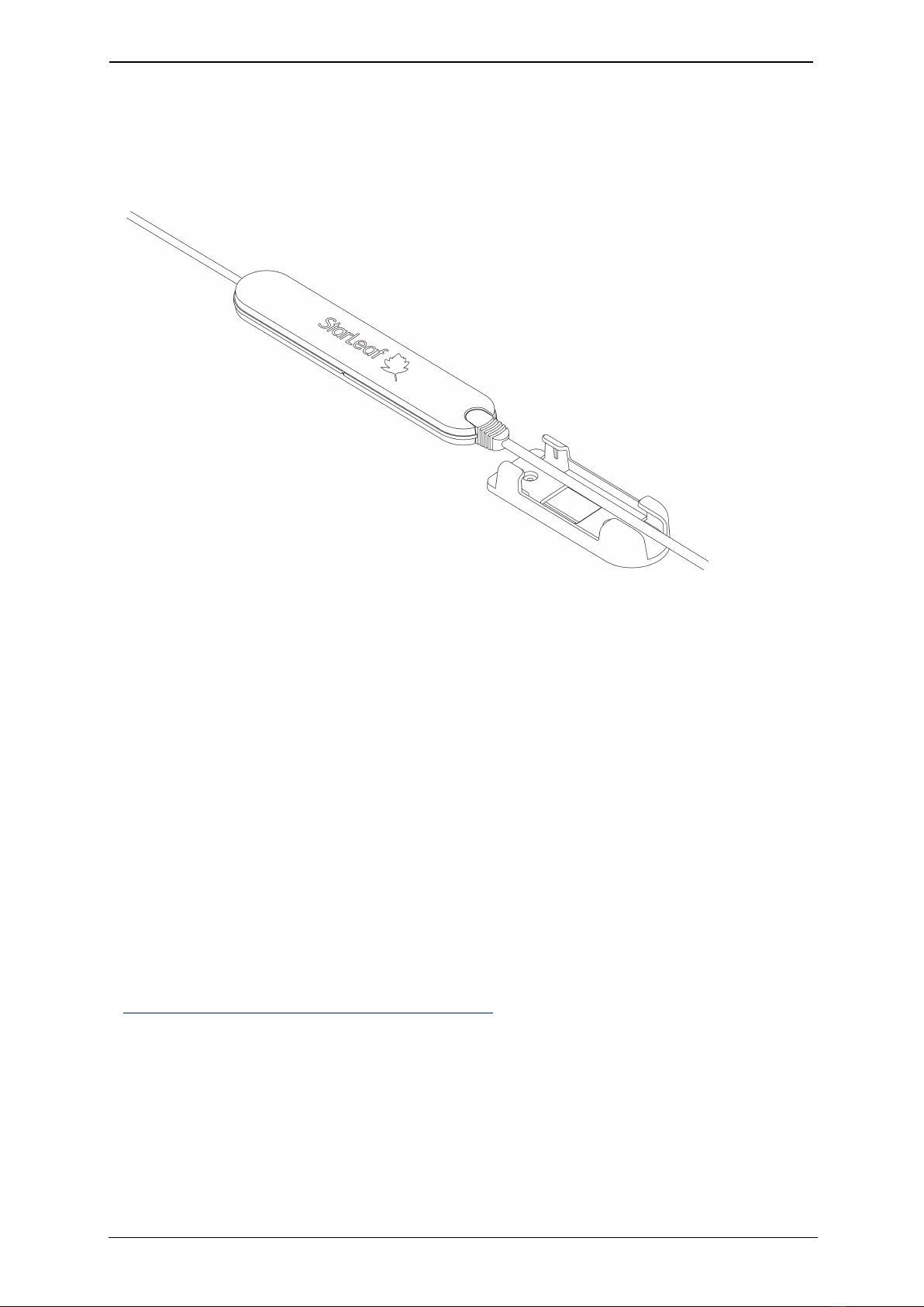
Mounting Pronto
The supplied bracket can be used to mount Pronto to a surface using screws,
ties (such as cable ties or Velcro), or adhesive mounting pads. Remove Pronto
from the bracket to access the screw holes and slots for ties:
Connecting presentation sources
Presentation sources can be connected to Computer In 1 and/or Computer
In 2 on the rear of the Teamline system to display content locally on room
displays and to share content during meetings. It is recommended that you
leave a cable within easy access on the meeting room table for this purpose.
A selection of adapters are supplied that can be used with the DVI-I to DVI-I
cable if the video output on the presentation source is not DVI-I (for example,
VGA, HDMI, DVI-D.)
To send audio from a presentation source, connect the audio out on the
device to the audio Line In on the system. Otherwise, participants will not
receive audio from the device.
Extending cables
For information about supported cable extenders and cable information, see
Cable recommendations for room systems.
Connecting power
Using the supplied power cable, connect the IEC mains power connector on
the rear of the system to the mains power.
Teamline 5250 Page 12
Configuring Teamline 5250
Configuring Teamline 5250
Before you can use the Teamline system, go to the Teamline configuration
web interface to:
nEnter the Quick Connect code to connect the Teamline system to the
Maestro management platform
nConfigure a proxy server (if required)
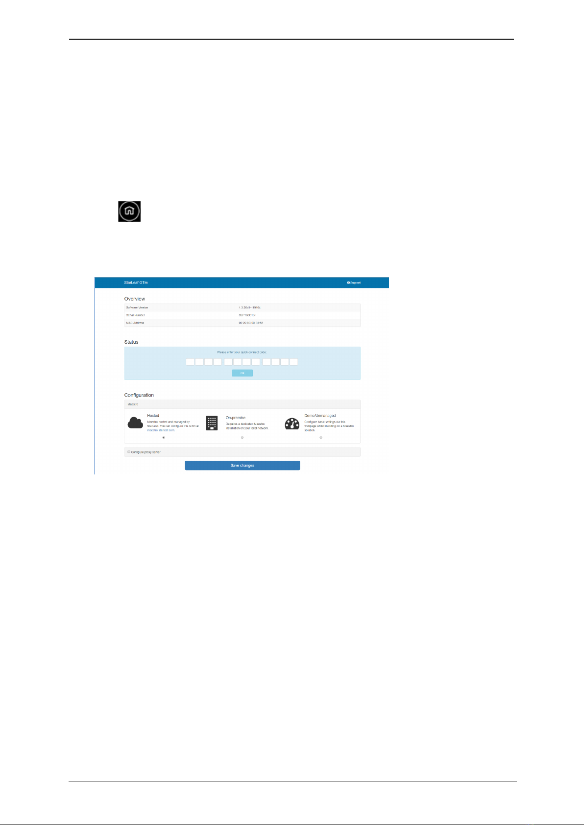
To access the configuration web interface:
1. Tap twice on the touchscreen controller to view settings, then tap
networking to view the IP address.
2. In a browser, enter this IP address in the address bar. The configuration web
interface is displayed:
3. Select Hosted if your system is managed by StarLeaf. Select On-premise if
you are using a local version of Maestro that has been installed by StarLeaf
on your local network.
Connecting the system to Maestro
To connect the Teamline system to Maestro:
1. Open the Maestro site. If you haven't created a new room for your Teamline
system, see the Maestro management platform guide on the Teamline
Knowledge Center.
2. In the Maestro Meeting Rooms page, click Manage next to the meeting
room to view the Quick Connect Code. Enter this code in the Teamline
configuration web page.
3. Click Save changes.

Teamline 5250 Page 13
Advanced Settings
Configuring the proxy server (optional)
Optionally, you can use the web interface to configure a proxy server:
1. If there is a proxy server for your deployment, select Configure proxy server.
2. Select Automatically detect settings or Manual configuration.
3. If you are using a setup script to configure the proxy server, enter the
location of the script in the Configuration script address field.
4. If the proxy server requires a user name and password, enter the details in
the Username and Passsword fields.
Changing system settings
To change the Teamline system configuration:
1. In the Maestro Meeting Rooms page, click Manage next to the relevant
room.
2. In the Info area, copy the unlock password.
3. In the Teamline configuration web interface, paste the password in the
Unlock field.
4. Click Unlock.
Using a static IPaddress
By default, the Teamline system uses DHCP to acquire an IP address. If
required, you can configure the system with a static IP address. In networking,
toggle DHCP off and tap to enter the IP address,netmask, and gateway
addresses.
Note: If the address entered is invalid, you are not notified on the
touchscreen. Ensure you enter the correct details.
Advanced Settings
Configuring EAPauthentication
To deploy the Teamline system into a network that is using 802.1x with EAP-TLS
authentication:
1. In a browser, enter the Teamline system IP address in the address bar. The
Teamline configuration page is displayed.
2. Select Configure 802.1x:

Teamline 5250 Page 14
Ports and protocols
3. Select the EAPmethod from the drop-down list.
4. Enter the identity of the server in the Identity field.
5. Click Choose File to browse to the location of the client certificate. If you do
not have a certificate from your Certificate Authority, click Generate new
signing request to request a certificate from your CA.
Ports and protocols
This is a list of ports and protocols used by the Teamline system. You will need
this if your network has Network Access Control (NAC) enabled, which
analyzes traffic from the unit for security purposes.
Room system connectivity
All source ports are ephemeral (1024-65535) unless otherwise specified.
Outbound
Port Host Protocol Notes
53 DNS server as defined in the network
configuration
TCP/UDP
(DNS)
Used to resolve domain
names or find services (for
example, in autodiscovery
on older configurations
using SRV or A records)
67 Broadcast
DHCP server
UDP
(DHCP)
Requests to DHCP server
443 *.maestro.starleaf.com
Local Maestro server
Note: * denotes either config or fw. If
you are using a proxy, the whitelist
should be *.maestro.starleaf.com and
maestro.starleaf.com if the first rule
doesn't cover this
TCP
(HTTPS)
Management server
connection (either hosted
or on-premise)

Teamline 5250 Page 15
Ports and protocols
Port Host Protocol Notes
5355 Windows devices TCP/UDP
(LLMNR)
Used to resolve names on
the local network
Inbound
Port Host Protocol Notes
68 DHCP server UDP (DHCP) Responses from
DHCP server
80 Any TCP (HTTP) Endpoint control
API
443 Any TCP (HTTPS) Web UI
On-premise Skype for Business 2015 or Lync 2013
All source ports are ephemeral (1024-65535) unless otherwise specified.
Outbound
Port Host Protocol Notes
80 lyncdiscover.domain
lyncdiscoverinternal.domain
autodiscover.domain
TCP (HTTP) Used in Lync and
EWS autodiscovery
88 AD server TCP/UDP Kerberos
authentication
443 Local webticket
ADFS wsfed servers
TCP (HTTPS) Various
authentication
modes for external
servers (also EWS
server)
3478 Edge server UDP
(STUN/MSTURN)
Used for external
user access to AV
sessions and media
(UDP)
5061 Front End server TCP (MTLS) Used for client-to-
server SIP traffic for
external user
access

Teamline 5250 Page 16
Ports and protocols
Port Host Protocol Notes
1024-65535 Front end server
Other client
UDP Audio, and video
(minimum of 40
ports required)
1024-65535 Front end server
Other client
TCP Audio, video, and
application sharing
1024-65535 Front end server
Other client
TCP (PSOM) Peer-to-peer file
transfer for
conferencing file
transfer. Clients use
PSOM
Teamline systems on external networks
If the Teamline system is not located on the same local network as the Skype
for Business deployment (that is, if it connects using the Edge server), the
following ports and protocols also apply.
All source ports are ephemeral (1024-65535) unless otherwise specified.
Port Host Protocol Notes
443 Edge server TCP (TLS) Used for client-to-
server SIP traffic for
external user
access
443 Edge server TCP (PSOM/TLS) Used for external
user access to web
conferencing
sessions
443 Edge server TCP
(STUN/MSTURN)
Used for external
user access to A/V
sessions and media
(TCP)
3478 Edge server TCP
(STUN/MSTURN)
Used for external
user access to A/V
sessions and media
(UDP)
1024-65535 Other client UDP Audio, and video
1024-65535 Other client TCP Audio, video, and
application sharing
50,000-59,999 Edge server UDP Audio, and video

Teamline 5250 Page 17
Ports and protocols
Port Host Protocol Notes
50,000-59,999 Edge server TCP Audio, video, and
application sharing
Skype for Business Online
The full range of Skype for Business Online IP addresses is available at:
https://support.office.com/en-us/article/Office-365-URLs-and-IP-address-
ranges-8548a211-3fe7-47cb-abb1-355ea5aa88a2?ui=en-US&rs=en-
US&ad=US&fromAR=1#BKMK_LYO
All source ports are ephemeral (1024-65535) unless otherwise specified.
Outbound
Port Host Protocol Notes
443 Skype for Business Online servers TCP (HTTPS) Webticket, wsfed
authentication
443 Skype for Business Online servers TCP (TLS) SIP signaling
443 Skype for Business Online servers TCP (PSOM/TLS) PSOM connections
web conferencing
443 Skype for Business Online servers TCP Audio, video, and
application sharing
(source port
depends on
configuration)
3478-3481 Skype for Business Online servers UDP Audio, video, and
application sharing
(source port
depends on
configuration)
50,000-59,999 Skype for Business Online
servers
Other client
TCP/UDP Audio (source port
50,000-50,019)
50,000-59,999 Skype for Business Online
servers
Other client
TCP/UDP Video (source port
50,020-50,039)
50,000-59,999 Skype for Business Online
servers
Other client
TCP Application sharing
(source port 50,040-
50,059)

Teamline 5250 Page 18
System LED behavior
Inbound
Port Host Protocol Notes
50,000-50,019 Skype for Business Online
servers
Other client
TCP/UDP Audio (source port
50,000-59,999)
50,020-50,039 Skype for Business Online
servers
Other client
TCP/UDP Audio (source port
50,000-59,999)
50,040-50,059 Skype for Business Online
servers
Other client
TCP Application sharing
(source port 50,000-
59,999)
System LED behavior
Network port LED
LED State
Link/Activity LED
(On the left when
looking at the port)
Solid yellow indicates there is a link, flashing when there is
activity, off when there is no link
Gigabit LED
(On the right when
looking at the port)
Green for 1000 Mbit/s link, off for 10/100 Mbit/s link or no link
StarLeaf Touch Port LED behavior
LED State
Link/Activity LED
(On the left when
looking at the port)
Solid yellow indicates there is a link, flashing when there is
activity, off when there is no link
Gigabit LED
(On the right when
looking at the port)
Green for 1000 Mbit/s link, off for 10/100 Mbit/s link or no link

Teamline 5250 Page 19
Camera comparison for Teamline 5250
Power and Status LED behavior
Power
LED
Status LED State
Solid
blue
Solid
yellow
Power has been applied to the unit, but it has not started
services yet
Solid
blue
Solid
green
The unit has booted up and everything is working properly
Solid
blue
Solid red There is a problem. This can indicate overheating and/or fan
failure
Camera comparison for Teamline 5250
The following cameras are supported with the Teamline 5250 system:
VHD-V61
The VHD-V61 camera is suitable for small to large meeting rooms. If required, it
can be mounted upside down.
Specs
nHorizontal field of view: 72.5°
nTeamline supports 1080p video calling @ 30fps
nDigital pan, tilt, and zoom
n5x digital zoom, 12x optical zoom
nCamera dimensions (W x H x D): 142 x 169 x 164 mm
nUpside down mounting available
nMounting shelf requirements: 150 x 195 x 200 mm to accommodate
connected cables and start up sequence
nHDMI cable length: 5 m
For information about installing the VHD-V61 camera and upside down
mounting, see Installing the VHD-V61 camera.
Sony SRG-120DH

Teamline 5250 Page 20
Installing the VHD-V61 camera
The SRG-120DH camera is suitable for small to very large meeting rooms.
Specs
nHorizontal field of view: 71°
nTeamline supports 1080p video calling @ 30fps
nDigital pan, tilt, and zoom
n5x digital zoom, 12x optical zoom
nCamera dimensions (W x H x D): 153 x 156 x 153 mm
nMounting shelf requirements: 160 x 200 mm
nHDMI cable length: 5 m
For more information about installing and using the Sony SRG-120DH camera,
refer to the Sony website.
Examples of the maximum field of view
VHD-V61 at 2m Sony SRG-120DH at 2m
Installing the VHD-V61 camera
Before you install the camera, read the following safety information:
nDo not subject the camera to rain or moisture
nTo prevent electric shock, do not remove screws or covers of the camera.
There are no self-serviceable parts. Refer to qualified service personnel for
servicing
nDo not operate under unspecified temperature, humidity or power supply
nUse the soft dry cloth to clean the camera. If the camera is very dirty, clean it
with diluted neutral detergent; do not use any type of solvent, which may
damage the surface
Table of contents
Other Teamline Conference System manuals

Popular Conference System manuals by other brands

VADDIO
VADDIO GroupSTATION 999-8900-000 Installation and user guide

3Com
3Com REMOTE ACCESS SYSTEM 1500 Getting started guide

The S.E.A. Group
The S.E.A. Group SmallTalk ST2-SR User instructions

Cardo Systems
Cardo Systems Freecom 4x manual

AT&T
AT&T MERLIN LEGEND MLX-10 Non-Display Telephone user guide

Autani
Autani EnergyCenter autaniNet/EnOcean Bridge quick start guide


Sena
Sena SRL-MESH quick start guide

Grandstream Networks
Grandstream Networks GAC2500 user manual

Sena
Sena Snowtalk 2 user guide

Elo TouchSystems
Elo TouchSystems Status Light Quick installation guide

Bosch
Bosch INTEGRUS Installation and operating manual

AT&T
AT&T Partner Plus Installation and programming guide