7
Gas Connection
General Overview
WARNING:
THE GAS SUPPLY HOSE SHOULD BE
INSPECTED PRIOR TO EACH USE. DO NOT USE A
GAS HOSE THAT HAS ABRASIONS, CUTS, DRY ROT
OR EXCESSIVE WEAR. IF DAMAGE IS PRESENT, THE
HOSE MUST BE REPLACED WITH A TEC-SPECIFIED
HOSE PRIOR TO USING THE GRILL. LISTS OF
REPLACEMENT PARTS ARE FOUND IN APPENDIX C
AND D.
WARNING:
WHEN YOUR GRILL IS STORED
INDOORS, REMOVE AND STORE THE LP GAS
CYLINDER OUTDOORS IN A PROTECTED, COOL AND
DRY LOCATION OUT OF REACH OF CHILDREN. THE
CYLINDER SHOULD NOT BE STORED IN A BUILDING,
GARAGE OR ANY OTHER ENCLOSED AREA.
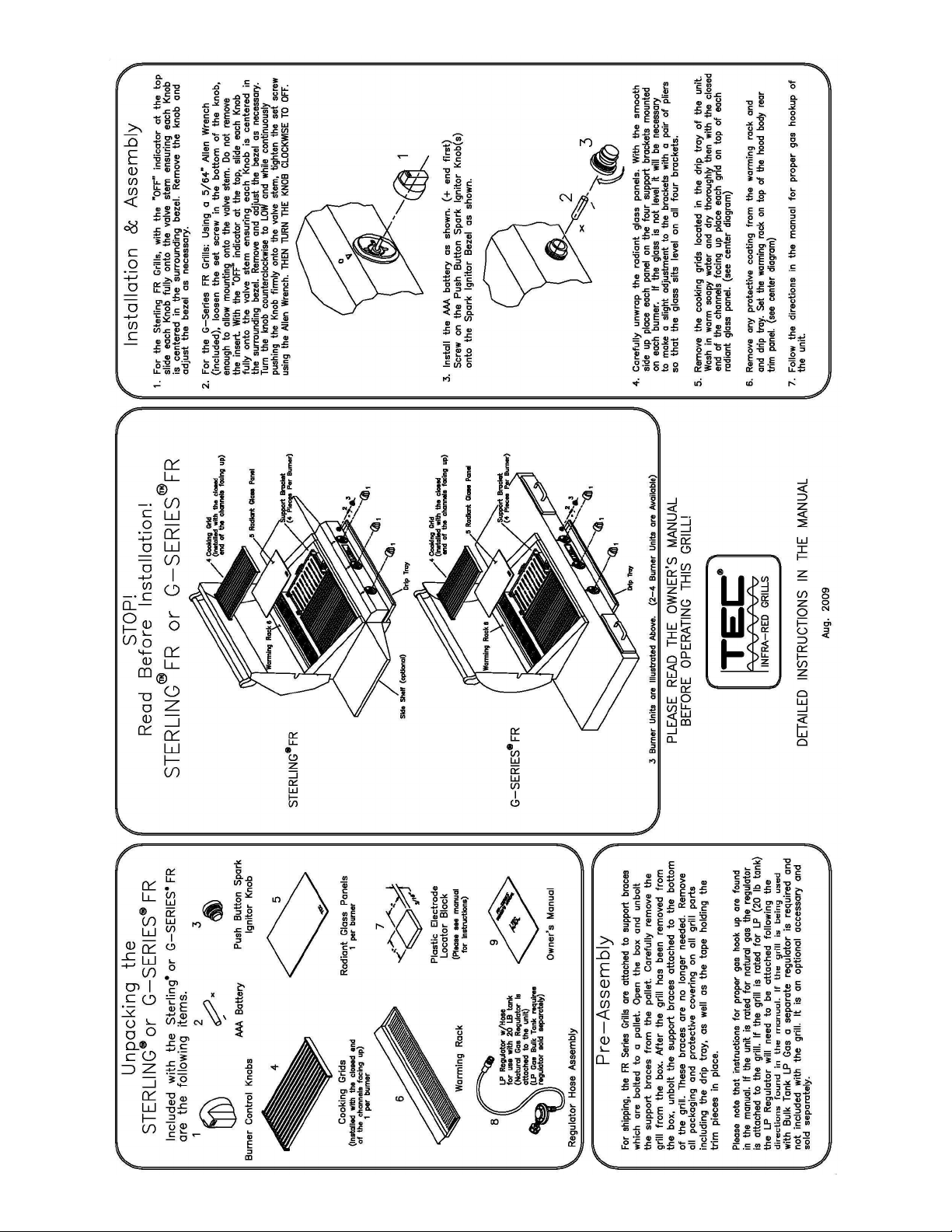
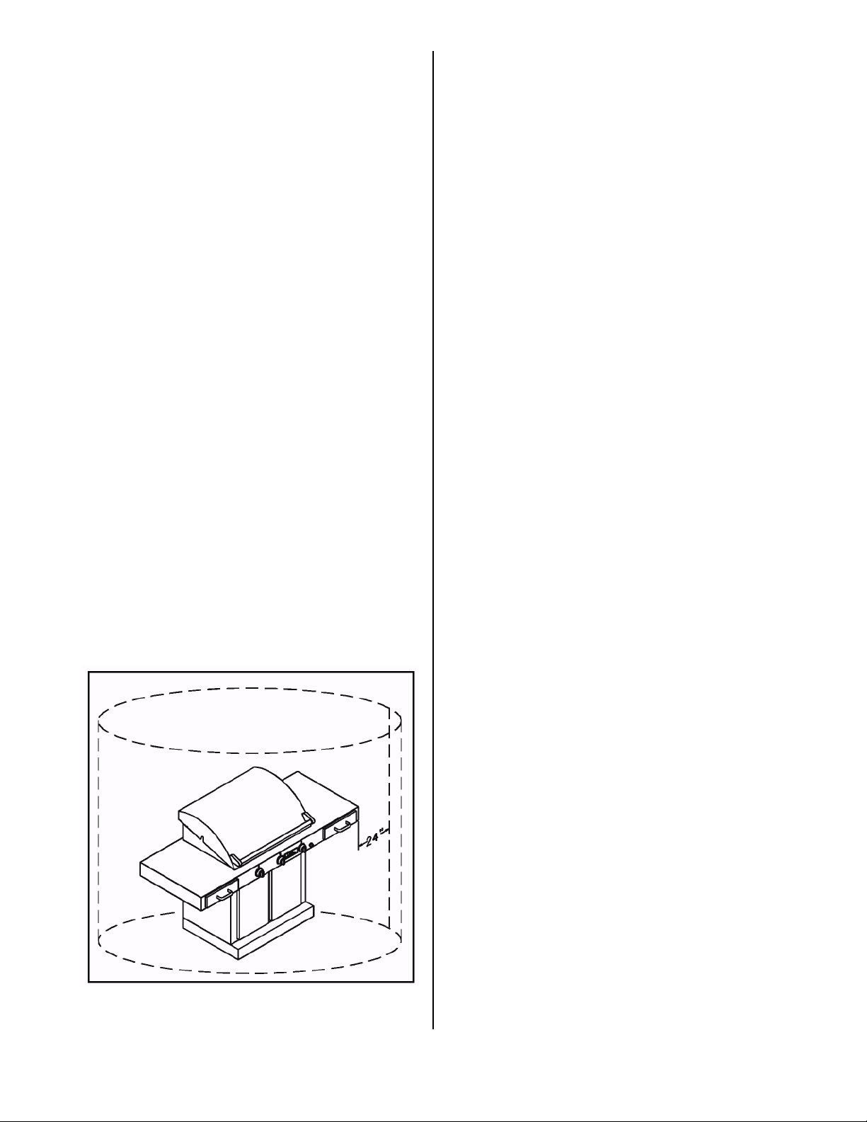
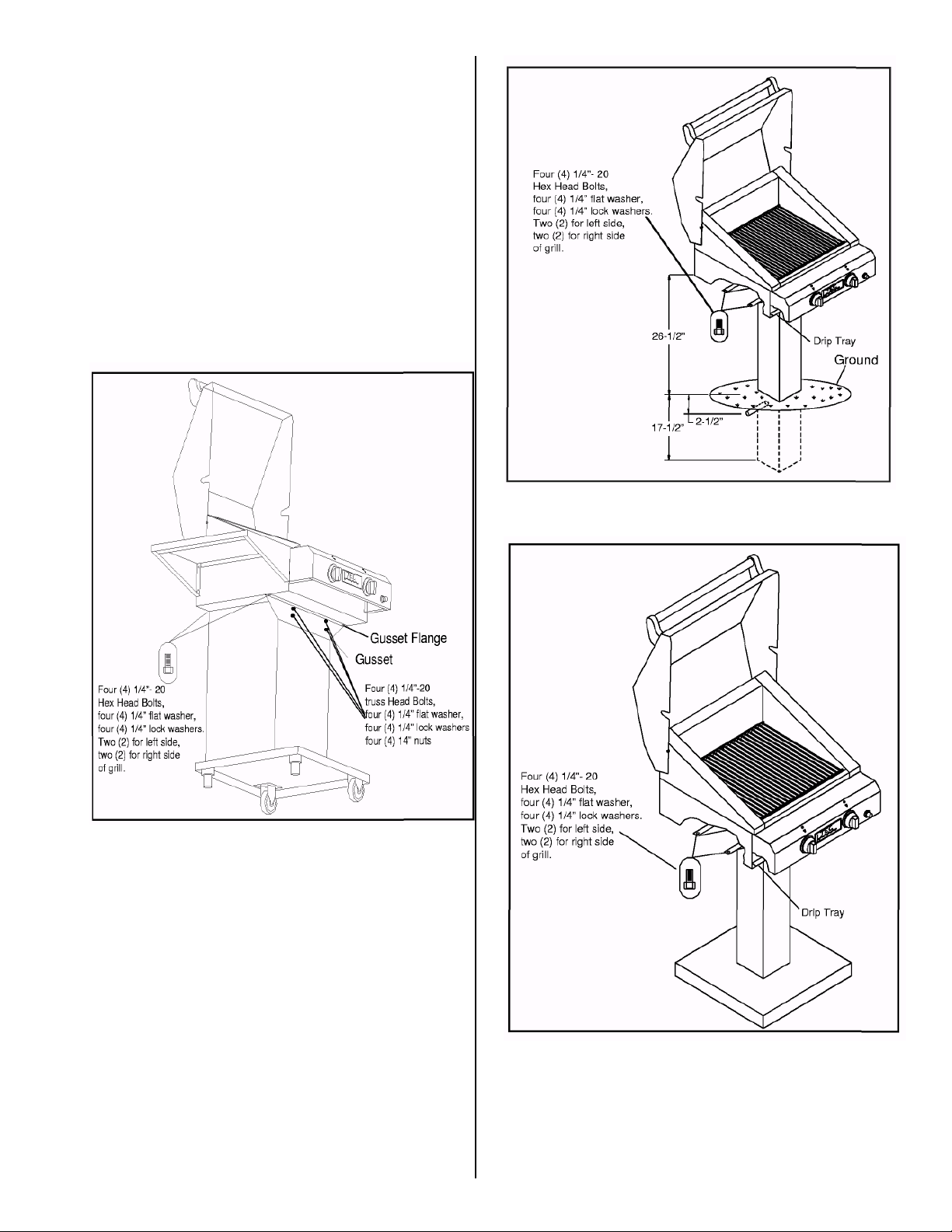
Follow the procedures outlined in this section closely to
ensure safe and proper grill operation. The Sterling FR
and the Sterling G-Series grills are offered in one of two
gas configurations: LP (Liquid Propane) or Natural gas.
Reference Table A.1 below for regulator specifications.
Grills that do not use LP gas with a standard 20 lb. LP
cylinder must be installed by qualified personnel. This
includes all Natural gas and permanently installed units
as well as LP Bulk Tank installations. Gas regulators
specified by TEC must be installed and used at all times.
Refer to Table A.1 below for gas supply specifications,
or see rating plate located on the grill.
LP Gas Cylinder Safety
WARNING:
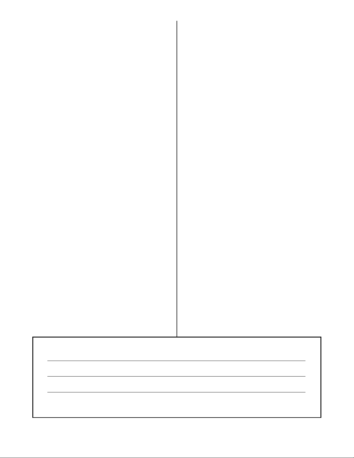
WHEN PURCHASED FOR USE WITH LP
GAS, THE STERLING AND STERLING G-SERIES
GRILLS COME WITH A REGULATOR ASSEMBLY
THAT USES A TYPE 1 CYLINDER CONNECTION
DEVICE. THIS DEVICE MUST BE USED WITH A TYPE
1 VALVE CYLINDER CONNECTION.
NOTICE:
AN LP GAS CYLINDER IS NOT PROVIDED
FROM THE FACTORY WITH THIS GRILL. HOWEVER,
ONLY APPROVED 20 LB. LP GAS CYLINDERS
CONSTRUCTED AND MARKED IN ACCORDANCE
WITH THE SPECIFICATIONS FOR LP GAS
CYLINDERS OF
THE U.S. DEPARTMENT OF TRANSPORTATION
(D.O.T) OR NATIONAL STANDARD OF CANADA,
CAN/CGA-B339, CYLINDERS, SPHERES AND TUBES
FOR THE TRANSPORTATION OF DANGEROUS
GOODS; AND COMMISSION, AS APPLICABLE
SHOULD BE USED. ALL APPROVED CYLINDERS
MUST BE EQUIPPED WITH AN INTEGRAL COLLAR
DESIGNED TO PROTECT THE CYLINDER VALVE
FROM DAMAGE, AS WELL AS A LISTED OVERFILL
PROTECTION DEVICE. DO NOT USE OR TRY TO
REPAIR A DAMAGED LP GAS CYLINDER AT ANY
TIME. CONTACT YOUR LOCAL LP GAS SUPPLIER
FOR REPLACEMENT. ALSO, YOU SHOULD ALWAYS
OBSERVE THE FOLLOWING PRECAUTIONS:
gDo not store a spare gas cylinder under or within 15
feet of this grill or any other open flame, heat
producing appliance or heat source.
gDo not fill your gas cylinder beyond 80% full.
gGas cylinders come with a pressure relief valve. If a
cylinder is subjected to excessive heat, the relief
valve will open and let highly flammable gas vapor
and/or liquid escape. Therefore, do not store gas
cylinders near or under an open flame or source of
heat. Store cylinders only in outside well ventilated
areas.
gPlace a dust cap on the cylinder valve outlet
whenever the cylinder is not in use. Only install the
type of dust cap on the cylinder that is provided with
the cylinder valve. Other types of caps or plugs may
result in leakage of propane.
WARNING:
FAILURE TO FOLLOW THE ABOVE
PRECAUTIONS COULD RESULT IN A FIRE CAUSING
DEATH OR SERIOUS INJURY OR PROPERTY
DAMAGE.
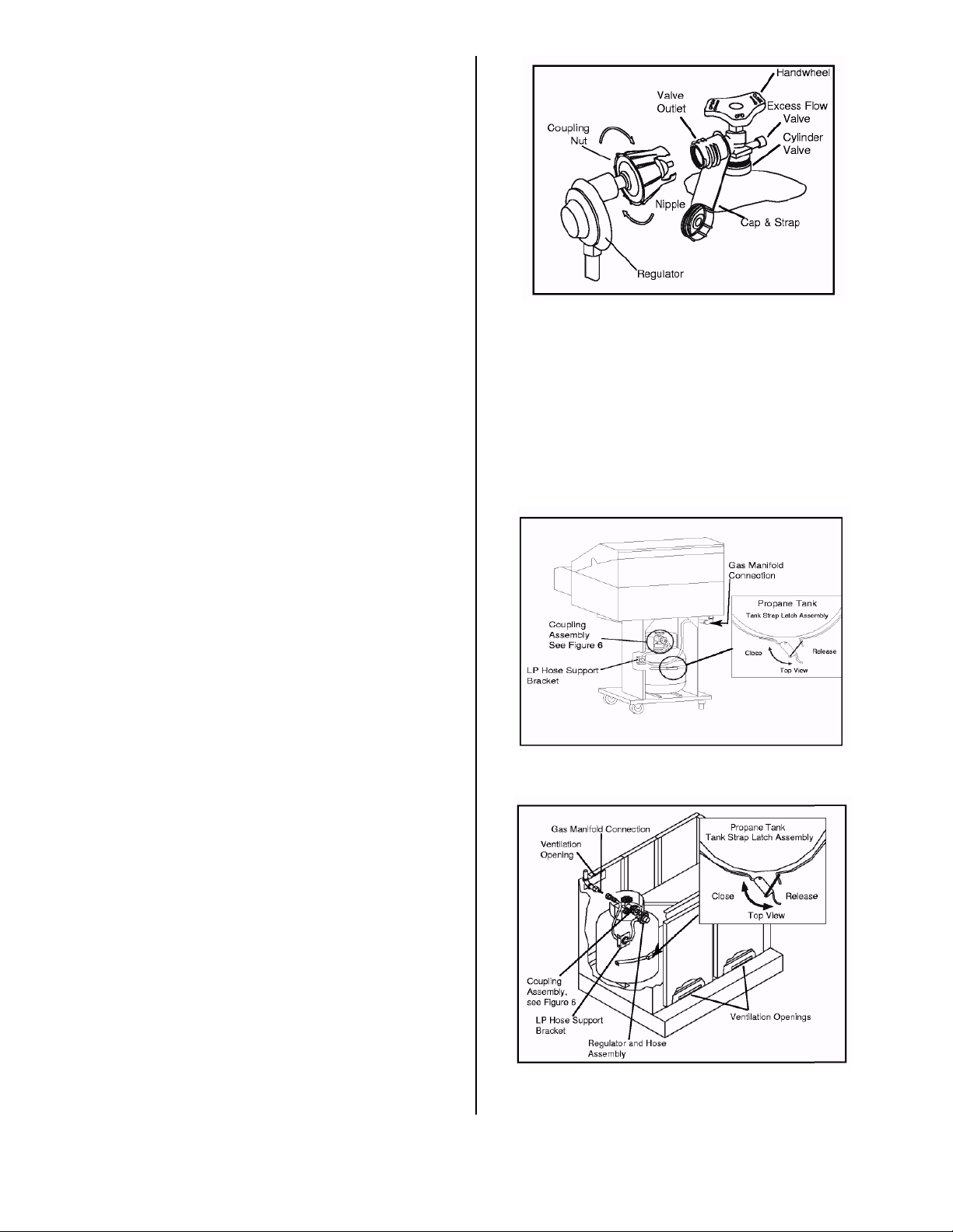
Installing Your LP Gas
Cylinder
NOTICE:
FOR YOUR SAFETY, ONLY USE THE
REGULATOR AND HOSE ASSEMBLY PROVIDED AS
ORIGINAL EQUIPMENT WITH YOUR GRILL OR, IF
REPLACEMENT PARTS ARE NECESSARY, USE ONLY
TEC-SPECIFIED REPLACEMENT PARTS.
GAS, REGULATOR AND
BASE TYPE
SUPPLY PRESSURE
(IN. WC (kPa),
MAX/MIN)
OPERATING
(kPa)
MAIN BURNER
ORIFICE SIZE
(DMS/DIA.)
BURNER INPUT
(BTU/HR. (W)/EA.)
Natural model RV-
stationary 14.0 (3.4)/5.0 (1.2) 4.0 (1.0) 49 (0.0730") 17,000 (4,983)
LP model RV-47L (LP)
stationary (LP Bulk Tank) 14.0 (3.4)/12.0 (3.0) 10.0 (2.7) 56 (0.0465") 16,000 (4,983)
LP (20 lb Tank) 125 psi (861), max 10.0 (2.7) 56 (0.0465") 16,000 (4,983)
Table A.1. Gas Supply Specifications