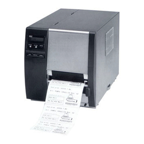
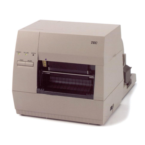
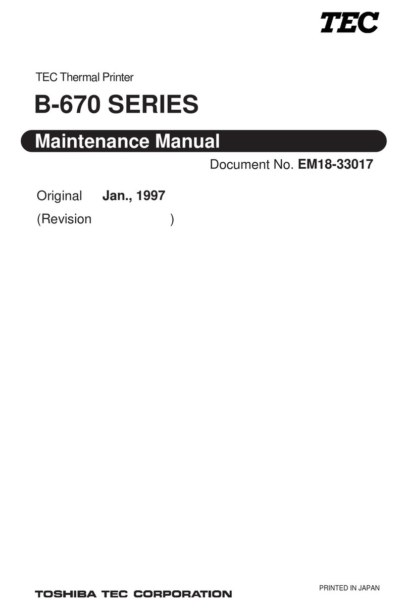
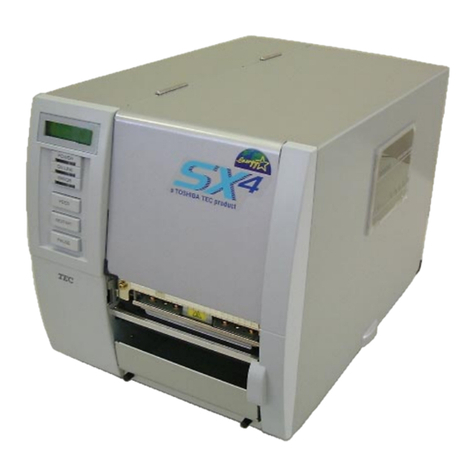
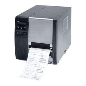
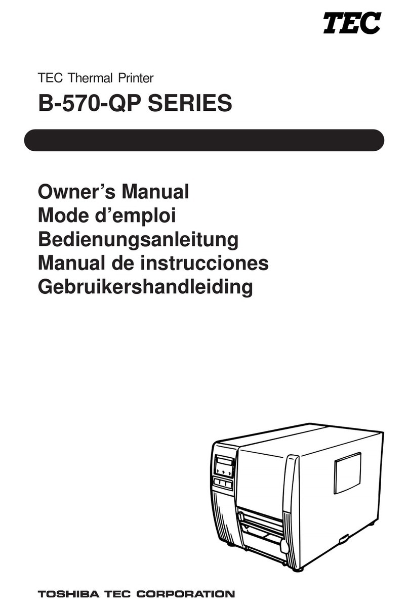
TEC B-672 Series User manual

NOTES: 1. Manual instructions must be followed when installing option kits or adding cables
to avoid system failures and to insure proper performance and operation.
2. Failure to follow manual instructions or any unauthorized modification,
substitution or change to this product will void the limited product warranty.
WARNING!
Follow all manual instructions. Failure to do so could create safety hazards such as fire or
electrocution.
Mantenimiento Periféricos Informáticos C/Canteras,15 28860 Paracuellos de Jarama Madrid Tel: 91 748 16 04 www.mpi.com.es
Page
EM18-33017
(Revision Date: Jul. 26 '99)
CAUTION:
1. This manual may not be copied in whole or in part without prior written permission of
TOSHIBA TEC.
2. The contents of this manual may be changed without notification.
3. Please refer to your local Authorized Service representative with regard to any queries
you may have in this manual.
Copyright © 1999
by TOSHIBA TEC CORPORATION
All Rights Reserved
570 Ohito, Ohito-cho, Tagata-gun, Shizuoka-ken, JAPAN
TABLE OF CONTENTS
1. UNPACKING ...................................................................................................... 1- 1
1.1 PROCEDURES........................................................................................... 1- 1
1.2 CHECKS ..................................................................................................... 1- 1
2. MAJOR UNIT REPLACEMENT.......................................................................... 2- 1
2.1 REPLACING THE CPU PC BOARD........................................................... 2- 2
2.2 REPLACING THE PS UNIT ........................................................................ 2- 4
2.3 REPLACING THE STEPPING MOTORS AND BELTS .............................. 2- 5
2.4 REPLACING THE RIBBON MOTORS........................................................ 2- 6
2.5 REPLACING THE PRINT HEAD ................................................................ 2- 6
2.6 REPLACING THE PLATEN ........................................................................ 2- 7
2.7 REPLACING THE ROLLER BELT AND FEED ROLLER ........................... 2- 8
2.8 REPLACING THE MEDIA SENSORS ....................................................... 2-10
2.9 PERIODIC MAINTENANCE PROCEDURE............................................... 2-11
3. INSTALLATION PROCEDURE FOR OPTIONAL EQUIPMENT ........................ 3- 1
3.1 CUTTER MODULE (B-4208-QM) ............................................................... 3- 1
3.2 MEMORY MODULE.................................................................................... 3- 4
3.3 STRIP MODULE (B-4908-H-QM) ............................................................... 3- 5
3.4 STABILIZER KIT .......................................................................................... 3-6
4. MECHANISM DESCRIPTION ............................................................................ 4- 1
4.1 CUTTER DRIVE.......................................................................................... 4- 1
5. TROUBLESHOOTING........................................................................................ 5- 1
6. DIAG. TEST OPERATION.................................................................................. 6- 1
7. PROGRAM DOWN LOAD .................................................................................. 7- 1
7.1 FLOPPY DISK............................................................................................. 7- 1
7.2 SETUP ........................................................................................................ 7- 1
7.3 DOWN LOAD PROCEDURE ...................................................................... 7- 2
7.4 ERROR CODE............................................................................................ 7- 3
Mantenimiento Periféricos Informáticos C/Canteras,15 28860 Paracuellos de Jarama Madrid Tel: 91 748 16 04 www.mpi.com.es
1-1
EM18-33017
1.1 PROCEDURE
1. UNPACKING
1.2 CHECKS
1) Check for damage or scratches on the machine.
2) Confirm that none of the accessories are missing.
NOTE: Keep the carton and side pads for later transport.
Carton
Thermal printer
Side Pad (L)
Accessory Board
Left/Right Side Holders Holder Shaft
Owner’s Manual
Unpacking
Procedure
Holder Base
Media
Holder
Thumbscrew (M-4x6)
Power Cord
Print Head Cleaner
Side Pad (R)
1. UNPACKING
1.1 PROCEDURE
1) Open the carton.
2) Unpack the accesories from the carton
3) Unpack the side pads (L)/(R) and the printer from the carton.
4) Place the printer on a level surface.
Fig. 1-1
Mantenimiento Periféricos Informáticos C/Canteras,15 28860 Paracuellos de Jarama Madrid Tel: 91 748 16 04 www.mpi.com.es

2-1
EM18-33017
2. MAJOR UNIT REPLACEMENT
CAUTION:
1. NEVER separate the ribbon motors from the attaching plate (bracket), because doing so will
change their adjustment. (See Fig. 2-8)
2. NEVER remove the two screws painted red on the side of the print block.
3. NEVER remove screws unless directed to do so in this manual. Removing screws may change
pre-set adjustments.
WARNING!
CAUTION:
1. Lubrication: During parts replacement
2. Kinds of oil: FLOIL G-488: 1 Kg can. (Parts No. 19454906001).
3. Do not spray the inside of the printer with lubricants. Unsuitable oil can damage the mechanism.
Screw (B-4x6)
Screw (B-3x8)
Left Side Cover
Bottom Plate
Top Cover
Screw (FL-4x6)
Right Side Cover
Screw (B-3x8) Fig. 2-1
2. MAJOR UNIT REPLACEMENT
Disconnect power cord before replacing important parts.
1) Turn the power off.
2) Open the right side and top covers.
3) Remove the six screws (FL-4x6, B-4x6 and B-3x8) to detach the left side cover.
4) Remove the (B-4x6) screw to remove the bottom plate.
NOTE : Instructionstoopenthetopandrightsidecoversandtoremovetheleftsidecoverareomitted
from each removal/installation procedure provided below.
■Lubrication
All machines are generally delivered in their best condition. Efforts shoud be made to keep them that
way. Lack of oil, or the presence of debris or dust, may cause an unexpected failure. To maintain in
optimaloperatingcondition,periodicallycleanthemachineandapplytheproperkindsofoiltoeachpart
in which librication is needed.
Although the frequency of lubrication varies according to how often the machine is used, as a minimum
it is necessary to lubricate before any part becomes dry. It is also necessary to wipe off excessive oil
or it will collect dirt.
2. MAJOR UNIT REPLACEMENT
Mantenimiento Periféricos Informáticos C/Canteras,15 28860 Paracuellos de Jarama Madrid Tel: 91 748 16 04 www.mpi.com.es

2-2
EM18-33017
2. MAJOR UNIT REPLACEMENT
CAUTION:
Replace only with the same type and rated fuse for continued protection against risk of fire.
NOTE: Be sure to support the CPU PC board when detaching the connectors.
3) Replace the CPU PC board and reassemble in the reverse order of removal.
Screw (SM-3x5B)
Connector
Screw (FL-3x5)
Screw (SM-3x5B)
CPU PC Board
2.1 REPLACING THE CPU PC BOARD
1) Detach the 11 connectors from the CPU PC board.
2) Remove the 7 screws (SM-3x5B and FL-3x5) to detach the CPU PC board.
Fig. 2-2
2.1 REPLACING THE CPU PC BOARD
Mantenimiento Periféricos Informáticos C/Canteras,15 28860 Paracuellos de Jarama Madrid Tel: 91 748 16 04 www.mpi.com.es
2-3
EM18-33017
2. MAJOR UNIT REPLACEMENT
CAUTION:
Be careful when replacing the CPU PC board, since a non-resettable counter (IC32) is installed on
thisboard. (Refer to Section 6.2.1 Maintenance Counter Printing.)If this counter should be reset,
replace IC32.
Fig. 2-3
Fig. 2-4
Range : 1V / 0.2 m sec.
Voltage
3.0 0.2V
VR1
GND
4) Adjust the ribbon end sensor.
After replacing the CPU PC board or changing ribbon type, be sure to adjust the ribbon end sensor
in the following procedure with the ribbon being used.
NOTE: Use TOSHIBA TEC-approved ribbons.
Set the ribbon so that the ribbon end sensor
can detect the ribbon, Turn the power on.
Turn the VR1 so that the voltage between Pin
1 (GND) and Pin 7 of CN10 is 3.0 ±0.2 V as
measured with an oscilloscope.
Turn the power off and mount the left side
cover and top cover.
5) Adjust the black mark sensor.
Referto page6-40 forthe adjustmentprocedure forthe blackmark sensorwhich isadjusted bykey
entries in system mode.
6) Adjust the feed gap sensor.
Refer to page 6-41 for the adjustment procedure for the feed gap sensor which is adjusted by key
entries in system mode.
2.1 REPLACING THE CPU PC BOARD
Mantenimiento Periféricos Informáticos C/Canteras,15 28860 Paracuellos de Jarama Madrid Tel: 91 748 16 04 www.mpi.com.es
2-4
EM18-33017
2. MAJOR UNIT REPLACEMENT
4) Replace the PS unit and reassemble in the reverse order of removal. Insert the PS cable into the
notch A .
Fig.2-5
Connecter
CPU PC Board
PS Cable
PS Unit Screw (FL- 4x6)
Screw (FL- 4x6)
A
2.2 REPLACING THE PS UNIT
CAUTION:
Replace only with the same type and rated of fuse for continued protection against risk of fire.
1) Detach all connectors from the CPU PC board.
2) Remove the two screws (FL-4 x 6) to detach the PS unit. Pushing the AC power inlet from behind
will ease the removal of the PS unit.
3) Disconnect the PS cable from the PS unit.
2.2 REPLACING THE PS UNIT
Mantenimiento Periféricos Informáticos C/Canteras,15 28860 Paracuellos de Jarama Madrid Tel: 91 748 16 04 www.mpi.com.es
2-5
EM18-33017
2. MAJOR UNIT REPLACEMENT
4) When replacing the stepping motor, place the platen belt around the pinion gear first, then the feed
rollerbelt,sothatthepartitionispositionedbetweenthetwobelts.Pressdownonthesteppingmotor
with 3.5 Kg ±300 g force and secure it so the platen belt and feed roller belt have no slack, are
engaged ,and evenly tense.
5) Reassemble in the reverse order of removal.
Screw (FL-4x6)
Front Plate
Screw (FL-4x6)
Platen Belt Feed Roller Belt
Screw (FL-4x6)
Fig. 2-6
CPU PC Board
CN14
Screw (SM-4x10C)
Stepping Motor
Fig. 2-7
2.3 REPLACING THE STEPPING MOTOR
1) Remove the 4 screws (FL-4x6) to detach the front plate.
2) Disconnect the cable from CN14 on the CPU PC board.
3) Removethetwoscrews(SM-4x10C),takethetwobeltsoffthepiniongear,andremovethestepping
motor.
2.3 REPLACING THE STEPPING MOTOR
Mantenimiento Periféricos Informáticos C/Canteras,15 28860 Paracuellos de Jarama Madrid Tel: 91 748 16 04 www.mpi.com.es
2-6
EM18-33017
2. MAJOR UNIT REPLACEMENT
CAUTION:
NEVER separate the ribbon motor from the attaching plate because doing so will change their
adjustment.
3) Replace the ribbon motors, then align the dowels to attach the ribbon motors. Reassemble in the
reverse order of removal.
2.5 REPLACING THE PRINT HEAD
Attaching Plate
Ribbon Motor
Screw (SM-3x5B)
Riboon Motor
Screw (SM-3x5B) Attaching Plate
FLOIL G-488 Connector
(Red) FLOIL G-488
Connector
(Black)
Dowels
Fig. 2-8
2.4 REPLACING THE RIBBON MOTORS
1) Remove the CPU PC board. (Refer to section 2.1.)
2) Detach the connector and remove the two SM-3x5B screws to detach the ribbon motors.
NOTE: This procedure can be done without removing the left side cover.
1) Remove the two (B-4x4) screws to detach the head cover plate.
2) Pull right to remove the front shaft.
Head Cover Plate
Screw (B-4 x 4)
Front Shaft Fig. 2-9
CAUTION:
1. NEVER touch the element when handling the print head.
2. NEVER touch the connector pins to avoid damage to the print head by static electricity.
3. NEVER remove the two screwws painted red on the side of the print block.
2.4 REPLACING THE RIBBON MOTORS
Mantenimiento Periféricos Informáticos C/Canteras,15 28860 Paracuellos de Jarama Madrid Tel: 91 748 16 04 www.mpi.com.es
2-7
EM18-33017
2. MAJOR UNIT REPLACEMENT
NOTE: Never remove the bracket.
6) Replace the print head and reassemble in the reverse order of removal.
7) Refer to page 6-44 and clear the maintenance counter.
8) Refer to page 6-31 and perform a test print.
2.6 REPLACING THE PLATEN
1) Remove the front plate. (Refer to Fig. 2-6.)
2) Loosen the two screws (SM-4 x 10C) securing the stepping motor.
3) Remove the (FL-4 x 6) screw to detach the platen positioning plate.
4) Take the platen belt off the platen pulley, move the platen fully to the right and remove the platen
from the left end.
Connector
Print Head
Head Fixing Screw
Head Lever
Connecter Fig. 2-10
3) Turn the head lever counterclockwise to lift the print head.
4) Remove the head fixing screw and pull out the print head.
5) Disconnect the two cables and remove the print head.
5) Replace and install the platen, then place the platen belt around the platen pulley.
6) Install the platen positioning plate.
7) Pressdown onthe steppingmotor with 3.5 Kg ±300 g force and secureit sothe platenbelt andthe
feed roller belt have no slack, are engaged and evenly tense.
8) Reassemble the remaining parts in the reverse order of removal.
Platen Belt
Platen Pulley
Platen
Screw (FL-4 x 6)
Platen Positioning Plate Fig. 2-11
2.6 REPLACING THE PLATEN
Mantenimiento Periféricos Informáticos C/Canteras,15 28860 Paracuellos de Jarama Madrid Tel: 91 748 16 04 www.mpi.com.es
2-8
EM18-33017
2. MAJOR UNIT REPLACEMENT
2.7 REPLACING THE ROLLER BELT AND FEED ROLLER
1) Lower the pinch roller lever.
2) Remove the white screw to detach the ribbon end sensor plate.
3) Remove the FL-3 x 5 screw, cut the cable band and remove the head-up switch.
4) Detach the connector of the ribbon end sensor.
5) Removal the pinch roller block.
NOTE: Fit both sides of the studs into the notches when installing the ribbon end sensor plate.
6) Remove the four E-rings (E-5), pinch roller holder, bush, pinch roller washer, and then roller belt.
Pinch Roller Block
Stud
Connector Cable Band FL-3 x 5
White Screw
Ribbon End Sensor Plate
Notch
Head-Up Switch
Pinch Roller Lever
Fig. 2-12
E-ring (E-5)
Bush
Pinch Roller Holder
Pinch Roller Washer
Roller Belt
E-ring (E-5)
Fig. 2-13
2.7 REPLACING THE ROLLER BELTAND FEED ROLLER
Mantenimiento Periféricos Informáticos C/Canteras,15 28860 Paracuellos de Jarama Madrid Tel: 91 748 16 04 www.mpi.com.es
2-9
EM18-33017
2. MAJOR UNIT REPLACEMENT
2.7 REPLACING THE ROLLER BELTAND FEED ROLLER
NOTE: Fit both sides of the studs into the notches when installing the media guide unit.
12) Replace and install the feed roller, place the feed roller belt around the feed roller pulley.
13) Install the feed roller positioning plate.
14) Press down on the stepping motor with 3.5 Kg ±300 g force and secure it so the platen belt and the
feed roller belt have no slack, are engaged and evenly tense.
15) Reassemble the remaining parts in the reverse order of removal.
Feed Roller Positioning Plate
Feed Roller Feed
Roller Pulley Feed Roller Belt
Stud Notch
Media Guide Unit
Screw (FL-4x6)
Media Plate
Screw (FL-4x6)
Fig. 2-14
7) Remove the two (FL-4x6) screws and detach the media plate.
8) Remove the two (FL-4x6) screws and detach the media guide unit.
9) Loosen the two (SM-4x10C) screws securing the stepping motor.
10) Remove the two screws to detach the feed roller positioning plate.
11) Take the feed roller belt off the feed roller, move the feed roller fully to the left and remove the feed
roller form the right end.
Mantenimiento Periféricos Informáticos C/Canteras,15 28860 Paracuellos de Jarama Madrid Tel: 91 748 16 04 www.mpi.com.es

2-10
EM18-33017
2. MAJOR UNIT REPLACEMENT
Movable Media Sensor
Media Sensor Unit
Upper Fixed Media Sensor
Knob
Fixed Media Sensor
E-ring (E-3)
Media Guide Plate
Screw (FL-3x4)
Connecter
Screw (SM-3 x 6B)
Media Guide Plate
White Screw
Clamp Fig. 2-16
Fig. 2-15
B
2.8 REPLACING THE MEDIASENSOR
2.8 REPLACING THE MEDIA SENSOR
CAUTION:
1. Whenusingthefixedsensor,lineupthefeedgapsensorsbetweentheupperandlowersensors.
2 Whenshippedfromthefactory, the black marksensorispositionedat the center oftheeffective
print area and the feed gap sensor is located 10 mm left of center as viewed from the front.
1) Detach the 4 connectors from the fixed/movable media sensors.
2) Remove the two screws (FL-3 x 4) and the sensor holder to detach the media sensor unit.
3) Turn the knob of the sensor shaft clockwise and remove the movable media sensor.
4) Remove the E-ring (E-3) from the sensor shaft and detach the lower fixed media sensor.
Connecter
5) Remove the white screw to detach the media guide plate.
6) Remove the two SM-3 x 6B screws, then unclamp and detach the upper fixed media sensor.
7) Replace the fixed/movable media sensors and reassemble in the reverse order of removal.
Mantenimiento Periféricos Informáticos C/Canteras,15 28860 Paracuellos de Jarama Madrid Tel: 91 748 16 04 www.mpi.com.es

2-11
EM18-33017
2. MAJOR UNIT REPLACEMENT
2.9 PERIODIC MAINTENANCE PROCEDURE
Allmachinesaregenerallydeliveredintheirbestcondition. Tomaintainoptimaloperatingconditionand
help gain maximum performance and life of machines, we would recommend you to conduct periodic
maintenance. Doing this is also effective in preventing unexpected troubles and avoiding wasteful
systemdown,bywhichmorebenefitisproducedtoyourcustomersandgreaterrelianceisplacedonthe
product quality.
Please refer to the following general maintenance procedure and perform periodic servicing.
NOTE: Beforestartingtheperiodicmaintenance,besuretoreadcarefullyandunderstandtheService
Manuals, especially warnings, cautions and adjustment.
1. Ask and operator or a manager about any machine trouble.
2. Check the run distance on the maintenance counter.
3. Unplug the power cord, and then open the printer cover.
4. Clean the inside of the printer.
1) The entire inside of the printer should be cleaned.
2) Wipe the platen and the feed roller with a cloth moistened with alcohol.
3) Clean the print head elements with a print head cleaner.
(Please instruct your customers to clean them daily.)
4) Clean the sensors.
5) Remove paper debris or label glue from the media path.
5. Apply FLOIL G-488 to the specified parts.
1) Apply grease to the cutter unit using a soft cloth.
Grease Grease
Clutch
Arm Fig. 2-17
Mantenimiento Periféricos Informáticos C/Canteras,15 28860 Paracuellos de Jarama Madrid Tel: 91 748 16 04 www.mpi.com.es
2-12
EM18-33017
2. MAJOR UNIT REPLACEMENT
NOTE: The above values of the cutter life are obtained on condition that the periodically maintained
cutter is used with TOSHIBA TEC-approved supplies by the proper method described in the
manuals.
8. Confirm each part adjustment. Make any necessary adjustments.
9. Conduct the following tests and make sure that there is no problem.
1) PrinttestwithTOSHIBATEC-specifiedmediaandribbon. (Printtone,print head position, etc.)
2) Paper skew
3) Print start position adjustment (Horizontal: Media position, Vertical: Sensor adjustment/
Adjustment by issuing commands)
4) Communication test
5) Abnorma noise
6) Confirm that there are not any other errors.
10. Mount the printer cover.
11. Clean the outside of the printer.
12. Fill out a report form. Hand it to the manager and obtain a signature.
2.9 PERIODIC MAINTENANCE PROCEDURE
No.
1
2
3
4
Part Name
Ribbon Motor
Cutter Unit (Option)
Platen
Feed Rooler
Part No.
FMBB0030501
FMBB0030502
GFM-0065001
FMBC0045501
FMBC0044601
Standard Interval of
Replacement
730 Km
1,000,000 cuts
50 Km
50 Km
6. Confirm that the problem occurs as reported, and then take corrective action.
7. Replace the following parts periodically, if necessary. The following table shows approximate
product life for each part.
Mantenimiento Periféricos Informáticos C/Canteras,15 28860 Paracuellos de Jarama Madrid Tel: 91 748 16 04 www.mpi.com.es
3-1
EM18-33017
3. INSTALLATION PROCEDURE FOR OPTIONAL EQUIPMENT
noitpircseDtinU/yt'QnoitpircseDtinU/yt'Q
tinUrettuC1wercSgnihcattArettuC2
rettuC1)6x4-LF(wercS2
senraHrettuC1)C6x4-MS(wercS1
troppuSrettuC1renaelC1
WARNING!
Make sure to unplug the power cord before installing any optional equipment.
3.1 CUTTER MODULE (B-4208-QM)
3. INSTALLATION PROCEDURE FOR OPTIONAL
EQUIPMENT
1) Open the right side cover and the top cover. (See Fig. 2-1.)
2) Remove the left side cover. (See Fig. 2-1.)
3) Remove the front plate. (See Fig. 2-6.)
4) Remove the screw (SM-4x8B) and two connectors to detach the operation panel.
5) Attach the cutter support to the main frame with the two screws (FL-4x6).
Connector
Main Frame Screw (FL-4x6) Screw (SM-4x8B)
Operation Panel
Connector
Cutter Support
Screw (FL-4x6) Fig. 3-1
3.1 CUTTER MODULE (B-4208-QM)
NOTE: This module cannot be used together with the B-4908-H-QM strip module. Remove the strip
module if it has been attached to the printer.
Mantenimiento Periféricos Informáticos C/Canteras,15 28860 Paracuellos de Jarama Madrid Tel: 91 748 16 04 www.mpi.com.es
3-2
EM18-33017
3. INSTALLATION PROCEDURE FOR OPTIONAL EQUIPMENT
6) Install the cutter unit with the attached four screws (cutter attaching screw, SM-4x6C and
FL-4x6).
7) Connectthe cutterharness toCN1 onthe cutterI/F PCboard throughthe openingof thecutter unit.
Cutter Unit
Screw (SM-4x6C)
Cutter Unit
Connector (CN1)
Opening
Cutter Harness
Cutter I/F PC Board
Cutter Attaching Screw Screw (FL-4x6)
Fig. 3-2
3.1 CUTTER MODULE (B-4208-QM)
9) Mount the cutter cover with the two screws.
CPU PC Board
Cutter Cover
Cutter Harness
Cutter Unit
Fig.3-3
Cutter Attaching Screw
Fig. 3-4
Screw
8) Connect the cutter cable to the CN15 on the CPU PC board.
Mantenimiento Periféricos Informáticos C/Canteras,15 28860 Paracuellos de Jarama Madrid Tel: 91 748 16 04 www.mpi.com.es
3-3
EM18-33017
3. INSTALLATION PROCEDURE FOR OPTIONAL EQUIPMENT
straPdevomeRtinU/yt'QstraPdevomeRtinU/yt'Q
etalptnorF1 )6x4-LF(wercS3
3.1 CUTTER MODULE (B-4208-QM)
10) Mount the operation panel and the left side cover on the printer.
11) Close the top and right covers.
12) Afterreassemblyiscomplete,performatestprinttoconfirmthatthecutterworksproperly.Iftheprint
startpositionbecomesmisalignwhenmediaisfedinthereversedirection,fineadjustthebackfeed
value using the Back Feed Fine Adjustment procedure in diag. mode.
NOTES: 1. If the top edge of label winds onto the platen in cut issue, set DIP SW. 1-5 to ON.
(Refer to the Owner’s Manual.)
2. Retain the parts that are removed during installation of the cutter unit. They will be
required when the printer is modified to a standard type.
■Adjusting the Cutter Guide Plates
After replacing the cutter unit the following adjustment procedure should be employed to prevent
paper jams.
1. Attach the cutter guide plate A with two SM-4 x 6C screw so that the fixed cutter is positioned
0.1 mm to 0.4 mm above the bottom of the cutter guide plate A.
2. Attach the cutter guide plate B with two FL-4 x 8 screws so that there is a clearance of 0.5 mm
between the cutter guide plate A and cutter guide plate B using a clearance gauge.
Fixed Cutter
Screw
(SM-4 x 6) Cutter Guide Plate B
Cutter Guide Plate A
Screw
(FL-4 x 8)
Fig. 3-5
0.1 ~ 0.4 mm
0.5 mm
Mantenimiento Periféricos Informáticos C/Canteras,15 28860 Paracuellos de Jarama Madrid Tel: 91 748 16 04 www.mpi.com.es

3-4
EM18-33017
3. INSTALLATION PROCEDURE FOR OPTIONAL EQUIPMENT
IC20
3.2 MEMORY MODULE
1) Open the right side cover and the top cover. (See Fig. 2-1.)
2) Remove the left side cover. (See Fig. 2-1.)
3) Remove the CPU PC board. (See Fig. 2-2.)
4) Directly connect the D-RAM PC board to CN20 on the CPU PC board, and then secure it with the
two locking supports.
CPU PC Board
Fig.3-6
(Revision Date Apr. 7 '98)
3.2 MEMORY MODULE
MAR yticapaC
ezisgniward.xaM )mm()H(x)W()lamron( eziagniward.xaM )mm()H(x)W()ylf-eht-no( skrameR
hctaBpirtStuc-otuAhctaBpirtStuc-otuA
BM26.892x6.0713.941x6.071dradnatS
BM49.999x6.0713.166x6.071noitpO
Locking Support
D-RAM PC Board Ass’y
Mantenimiento Periféricos Informáticos C/Canteras,15 28860 Paracuellos de Jarama Madrid Tel: 91 748 16 04 www.mpi.com.es
This manual suits for next models
1
Table of contents
Other TEC Printer manuals

TEC
TEC B-370 Series User manual

TEC
TEC B-450 SERIES User manual

TEC
TEC B-SX4T-QQ User manual

TEC
TEC B-680 Series User manual

TEC
TEC B-670-QQ User manual

TEC
TEC B-570-QQ SERIES User manual

TEC
TEC TEC EO1-32004 User manual

TEC
TEC BRST-10 SERIES User manual

TEC
TEC TEC B-670 SERIES User manual

TEC
TEC TEC B-870 SERIES User manual

TEC
TEC TEC B-670 SERIES User manual

TEC
TEC B-450 SERIES User manual

TEC
TEC B-450-QP SERIES User manual

TEC
TEC B-570 SERIES User manual

TEC
TEC B-570-QP Series User manual

TEC
TEC CB-416-T3-QQ User manual

TEC
TEC CB-426-T3-QQ User manual

TEC
TEC B-880 series User manual

TEC
TEC TEC EM1-33033 User manual

TEC
TEC B-450-QQ Series User manual