Centrodyne Silent Series User manual

General-Purpose Thermal Printer
Silent Series
Model 160
Installation and User Guide

160 User Guide Revision 1.2.1
2/12
Centrodyne Inc., All rights reserved.
The information in this document is the property of Centrodyne Inc.
Reproduction or transcription by any means, in whole or in part,
without the prior written consent of Centrodyne Inc., is prohibited.

160 User Guide Revision 1.2.1
3/12
Table of Contents
Warranty......................................................................................................................................................... 4
Installation...................................................................................................................................................... 4
Package Contents........................................................................................................................................ 4
Finding a Suitable Installation Surface....................................................................................................... 4
Installing with a Centrodyne S600 Taximeter............................................................................................ 6
Installing with a Data Terminal.................................................................................................................. 6
Using the Model 160 Printer .......................................................................................................................... 8
Controls and Indicators............................................................................................................................... 8
Loading the Paper....................................................................................................................................... 9
Printing..................................................................................................................................................... 10
Printing Configuration Data ..................................................................................................................... 11
Clearing Paper Jams ................................................................................................................................. 11
Contact Centrodyne...................................................................................................................................... 12

160 User Guide Revision 1.2.1
4/12
Congratulations on the purchase of your Centrodyne Model 160 portable printer. The 160
is a high-speed, general purpose thermal printer primarily intended for in-vehicle
installation and use. Please read this entire guide carefully before attempting to install and
use your printer. Please, carefully read and observe all notes in the boxes.
Warranty
The model 160 printer comes with a 1-year limited manufacturer’s warranty starting from
the date of purchase. This warranty covers all electronic and mechanical parts with the
exception of the print-head mechanism itself. This mechanism is only covered for the
first 30 days after the date of purchase. The warranty covers all defects in parts and
manufacturing. The warranty does not cover problems due to improper installation and/or
use, damage caused by mishandling, dropping, vehicular accidents, static electrical
discharge, exposure to intense magnetic fields or radiation, spilling, immersion in water
or other liquids, exposure to temperatures outside of the specified limits, and all other
causes deemed by Centrodyne as not related to the manufacturing process.
The customer is responsible for the cost of shipping the product back to Centrodyne’s
service center for warranty service. The item will be returned at Centrodyne’s expense.
Installation
Package Contents
Depending on your order the package contents of your Model 160 printer may not
contain all the items specified below:
Centrodyne Model 160 printer (1)
Direct-power cable (1)
#4 or M3 mounting screws (2)
Mounting nuts (2)
Installation and User Guide (1)
Model 160 Specification Document (1)
Finding a Suitable Installation Surface
The Model 160 printer can be installed at any angle between 0oto 90o. (Figure 1) A
suitable mounting surface should:
Have an angle no greater than 90ofrom the horizontal. (Figure 1)
Have sufficient room at the printer RJ-45 jack to accommodate the mating
connector and cable. (Figure 2)
Have sufficient clearance for opening the printer door and loading paper.
(Figure 3)
Provide access to the platen-release lever. (Figure 4)
Have threaded holes (or back-side access to attach nuts to the mounting screws)
located to match the printer mounting holes. (Figure 5)

160 User Guide Revision 1.2.1
5/12
Figure 1 Figure 2
Figure 3 Figure 4
Figure 5
Mounting
Holes

160 User Guide Revision 1.2.1
6/12
Installing with a Centrodyne S600 Taximeter
When installing the Model 160 with a Centrodyne S600 taximeter there is no need to
separately wire power and ground into the unit. These are provided through the cable
connecting the Model 160 and the taximeter.
Step 1: Once a suitable mounting location has been selected verify that the taximeter
cable will reach the printer in the selected location and that there is ample room to insert
the RJ-45 connector into the printer.
Step 2: Mount the printer securely to the mounting surface.
NOTE: Avoid excessive tightening of the mounting screws as this may cause
the printer case to crack.
Step 3: Attach the RJ-45 connector. Check that the power indicator is lit. Use the
taximeter to perform a printer test (print receipt or statistics). You may also print the 160
configuration data as a printing test. (see Printing Configuration Data section of this
guide)
Installing with a Data Terminal
When installing the Model 160 with a data terminal you may require a direct-power cable
(available from Centrodyne) or power may be provided by the data terminal. If power is
provided by the data terminal then skip step 3 below.
Step 1: Once a suitable mounting location has been selected verify that the data terminal
cable will reach the printer in the selected location and that there is ample room to insert
the RJ-45 connector into the printer. If installing the 160 using a direct-power cable then
ensure that the power and ground wires can reach the power source when the 160 is
securely mounted.
Step 2: Mount the printer securely to the mounting surface.
NOTE: Avoid excessive tightening of the mounting screws as this may cause
the printer case to crack.
Step 3: Attach the power (red) and ground (black) wires to a 12V power source.
NOTE: Always use a 12V power source when powering the printer. The power
source must be capable of supplying a sustained current of at least 2 Amps. Use of
lower voltage or current power sources may cause damage to the printer.

160 User Guide Revision 1.2.1
7/12
NOTE: The red power wire should be wired to the 12V source through a 5 Amp
fuse. (NOT supplied by Centrodyne) You may be able to locate one in the vehicle
fuse box; otherwise an inline fuse may be used.
Step 4: Attach the RJ-45 connector. Check that the power indicator is lit. You may print
the 160 configuration data as a printing test. (See Printing Configuration Data section of
this guide)

160 User Guide Revision 1.2.1
8/12
Using the Model 160 Printer
Controls and Indicators
The model 160 printer has 2 LEDs at the front of the unit, next to the RJ-45 connector.
The red LED indicates that the printer is powered. The green LED lights when the printer
is printing.
Figure 6
The model 160 printer has a release lever on the right-hand side of the printer. This lever
is not visible when the door is closed.
Figure 7
The button on the top-front of the printer is the paper-feed button.
Indicator
LEDs
Door
Release
Release
Lever
Paper
Feed
Button
Tear
Bar

160 User Guide Revision 1.2.1
9/12
Loading the Paper
NOTE: The 160 printer accommodates paper rolls with the following maximum
dimensions:
- Thickness: 0.08 mm
- Width: 58 mm (approx 2 ¼”)
- Diameter: 48 mm (75-85 feet long)
Using larger/thicker paper roles may damage the printer.
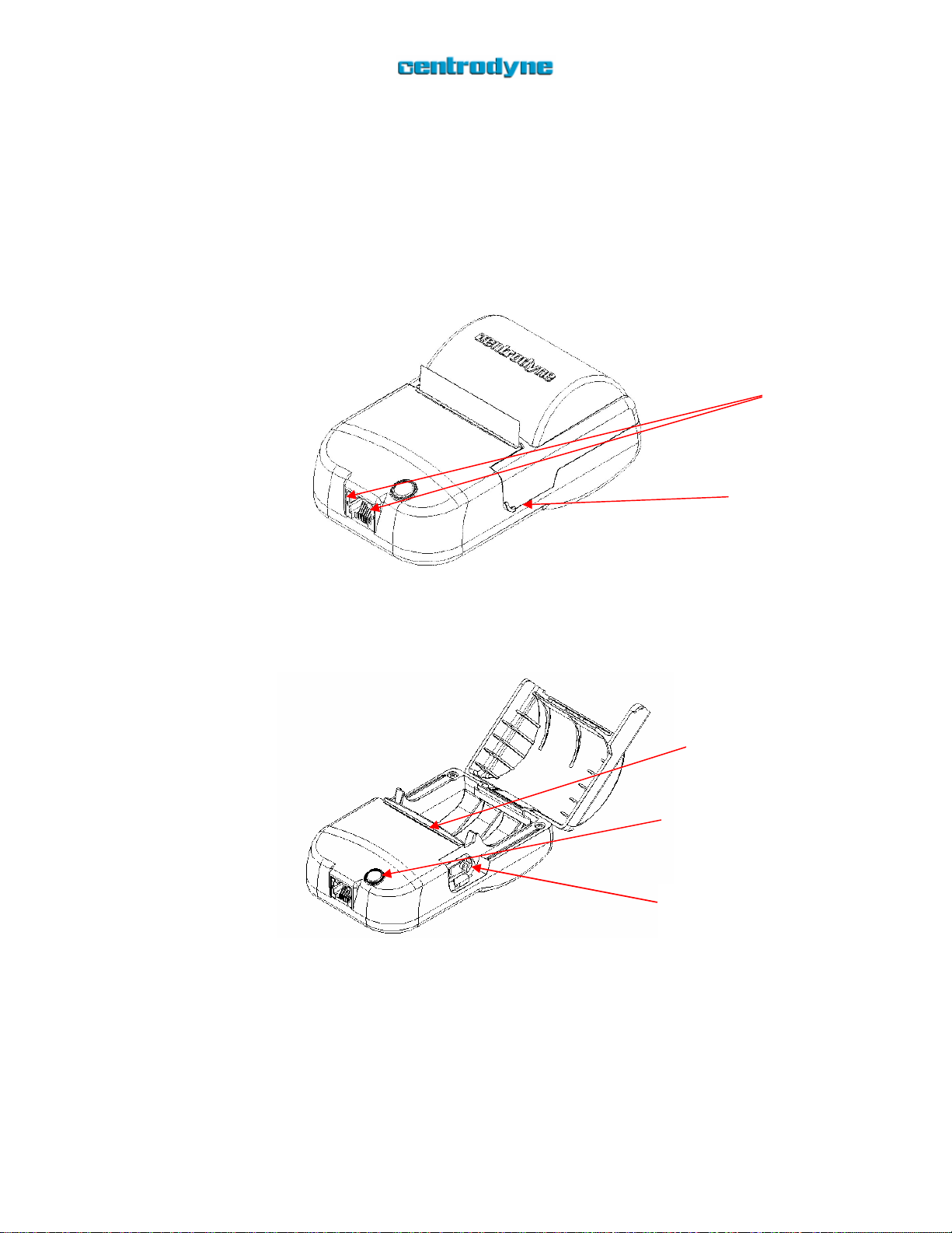
Make sure that the red LED is lit indicating that the printer is powered.
Locate the door release with your right forefinger and lift upwards to open the
printer door.
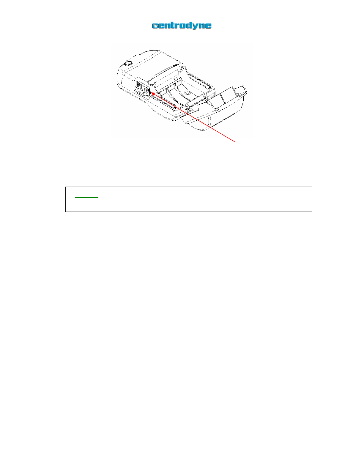
The printer is equipped with a double-action green lever to make paper loading
and clearing jams easier. This lever can sit in 3 different positions: CLOSED,
ADJUST, and OPEN. When the printer door is closed the lever is automatically
forced into the CLOSED position. When loading the paper, make sure that the
lever is in the CLOSED position.
Unroll approximately ½”- ¾” of paper from the end of the roll. Hold the unfurled
portion of paper between your right thumb and forefinger while grasping the
paper roll in the palm of your right-hand.
Insert the unfurled portion of the paper into the slot below the printer platen
(roller bar). Try to ensure that the paper is squared with the printer mechanism as
loading the paper at an angle may cause jamming.
The 160 has an auto paper load feature. Once the unfurled portion of the paper
role has been detected (the sensor is on the same side of the printer mechanism as
the lever) the printer motor will automatically engage for approximately 2
seconds, pulling the paper through.
If the paper is not pulled all the way through you may hold down the paper-feed
button. The printer motor should engage and pull the paper the rest of the way.
If the paper has not been pulled through this means that the printer mechanism
was not able to catch the paper. You need to push the paper further into the slot so
that the printer mechanism can catch it.
Drop the paper roll into the paper roll compartment making sure that there is no
slack or unfurled paper between the paper roll and the printer mechanism.
Place the lever into the ADJUST position by pushing back on the serrated edge of
the green lever until you feel it snap into place. (Figure 8)
With your fingers, pull the paper until at least 2 inches of paper is coming out of
the exit slot. With a thumb and forefinger on each side of the 2” paper strip
straighten the paper and make sure that the edges of the paper at the printer exit
are smooth and not bunched up.
Close the printer door! The 160 is now ready to print.

160 User Guide Revision 1.2.1
10/12
Figure 8
NOTE: The 160 printer door must remain closed when printing. Printing with
the door open may result in poor results and/or damage to the print-head.
Printing
The printer door should be securely closed whenever the unit is printing.
Once the printing has completed you may tear the paper.
For best results when tearing there should be at least an 1/8” of white space
between the end of the print and the tear bar. You may need to press the paper-
feed button to ensure a clean tear.
Grasp the topmost portion of the printed paper between thumb and forefinger of
your right or left hand and gently pull back so that the paper is resting against the
tear bar.
Apply gentle pressure until the paper begins to tear at the edge.
Once the paper edge has torn, complete the tear with one quick motion, pulling
the paper towards the front of the printer.
Push back
here

160 User Guide Revision 1.2.1
11/12
Printing Configuration Data
You can have the 160 print out its configuration data using the following procedure:
Make sure that the printer is powered off. (RJ-45 removed)
Press and hold the paper-feed button.
Power up the printer by inserting the RJ-45 connector (attached to the cable) into
the front of the printer.
A configuration data report should print out.
Clearing Paper Jams
Although the 160 was designed to avoid paper jams, it is possible that the paper will
occasionally jam the print mechanism. Follow the procedure below to clear paper jams.
DO NOT open the printer case.
Open the printer door.
Tear the paper roll at the entrance of the paper slot and remove the paper roll.
Figure 9
Press and hold the paper-feed button until the printer ejects the jammed paper.
If the above procedure does not clear the paper jam then move on to the next set of steps:
Place the green release lever into the OPEN position.
NOTE: The release lever is a double-action release. To open the release lever
first push back on the lever and then lift as shown in Figure 10. If you do not fully
release the lever before proceeding you may cause damage to the print
mechanism.
Paper
Feed
Slot
Entrance

160 User Guide Revision 1.2.1
12/12
Figure 10
With the release lever in the open position, insert a piece of soft, semi-rigid
cardboard or paper into the paper feed slot and push through until you see it rise
above the tear bar. This should clear all debris from the mechanism.
Close the printer door.
NOTE: You do not need to push down on the release lever. Closing the printer
door automatically pushes the release lever into the proper position.
Contact Centrodyne
For technical support or service you may email or call us at:
United States and Canada International
1-800-655-5575 01-514-331-8760
1-800-679-9939
Step 1:
Push back
here
Step 2:
Lift up
here
This manual suits for next models
1
Table of contents
Popular Printer manuals by other brands

Konica Minolta
Konica Minolta Magicolor 4650 brochure

FARGO electronics
FARGO electronics PERSONA C30 user manual

Siemens
Siemens TELEPRINTER 100 operating instructions

Kyocera
Kyocera KM-4530 Operation guide

Epson
Epson U220B - TM Two-color Dot-matrix Printer Technical reference guide

VEVOR
VEVOR VG-L5 user guide