Blackrock Microsystems Pro60 Owner's manual

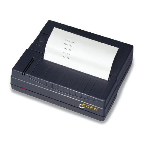
Blackroc Pro60 Thermal Printer
Programming Manual
March 2007
V1.4

Revision Date Details
V1.0 November 2006 Initial release
V1.1 December 2006 Additional specifications added and form control codes
clarified.
V1.2 anuary 2007 Added description of setup using the OPD menu system.
V1.3 March 2007 Added description of storing 'batch' files. Clarified graphic
commands.
V1.4 March 2007 Clarified font selection command.

Table of Contents
1Introduction........................................................................................................................................ 3
2Specifications..................................................................................................................................... 3
3Key Functions.....................................................................................................................................3
4OPD Menu..........................................................................................................................................4
5Bluetooth Configuration.....................................................................................................................5
6Escape Code Programming................................................................................................................ 5
6.1Print Commands......................................................................................................................... 6
6.2Positioning.................................................................................................................................. 6
6.3Formatting Characters.................................................................................................................7
6.3.1Selecting Character Sizes....................................................................................................7
6.3.2Character Spacing & Colour............................................................................................... 7
6.3.3Print Orientation & Density Adjustment............................................................................ 8
1.1.1 Graphic Commands...........................................................................................................8
6.3.4Form Control.....................................................................................................................10
6.3.4.1Control by paper length.............................................................................................10
6.3.4.2Control by Markers................................................................................................... 10
6.3.5Batch Files.........................................................................................................................11
6.3.6Batch Files Description.....................................................................................................11
6.4Character Set.............................................................................................................................12
6.5Example WinCE Application – Escape Commands Version................................................... 13
6.5.1Source Code...................................................................................................................... 13
7WinCE Printer Driver Programming................................................................................................17
7.1Example WinCE Application – Printer Driver Version........................................................... 17
7.1.1Source Code...................................................................................................................... 17

1 Introduction
The Pro60 printer is a self contained portable printer that may be optionally fitted to the rear of a
PsionTeklogix Workabout Pro (7525) portable computer. The printer accepts rolls of paper that are
58mm wide and with a maximum outside dimension of 34mm. Connectivity is provided by a
Bluetooth link.
2 Specifications
Printing method Thermal
Number of dots 384
Resolution (dots/mm) 8
Resolution (dpi) 203
Printing width (mm) 48
Paper width (mm) 58
Max. paper thickness (um) 80
Paper loading Easy loading
Printing speed (mm/s) 60
Paper detection Opto sensor
Temperature detection Thermistor
Head-up or Cover-open detection Combined with opto sensor
Life/reliability 50km
Operating temperature (°C) 0 to 50
Operating humidity (%) 20 to 85 non condensing
3 Key Functions
NEXT ENTER
The keys can be used for different functions depending upon the mode of the printer. If the printer
is in normal printing mode, the following table shows the key functions.

The last item in the table shows how to change mode and access the OPD menu.
Key 'ENTER' Key 'NEXT' ction
Pressed Not Pressed Feed paper one line
Held down for more than 2s Not Pressed Continuous paper feed
Pressed during power on for
less than 1 s
Not Pressed Reactivation, no paper feed
Held down during power on for
more than 2s, with paper
detected.
Not Pressed Retrieval of T0 (self test)
Held down during power on for
more than 2s, with no paper
detected.
Not Pressed Set in hex dump mode
Pressed whilst in hex dump
mode
Not Pressed End hex dump mode
Not Pressed Key released after less than 1s
in normal paper mode
Retrieval of T1 (form feed)
Not Pressed Key held down for greater than
3s
Retrieval of T1 (immediate
power down)
Pressed Pressed Calls OPD menu
4 OPD Menu
The Pro60 may be setup by use of the buttons on the front face of the unit. By pressing the buttons
as instructed by the prompts printed on the paper. Various parameters can be set by use of the OPD
(On Paper Display) menus.
The OPD menu is entered by pressing, holding, then releasing the ENTER and NEXT buttons. A
'welcome' print will be made on the paper, showing the menu of settings.
The menu may be exited by pressing again the ENTER and NEXT to save and exit, or it may be left
for a period of time (10 minutes) after which it will automatically exit.
Items that may be changed are;
Density
20, 25, 30, 35, 40, 45, 50, 90 (2 ply)
Speed/Quality
Low(32)/Medium, Medium(64)/Medium, Medium(64)/Low, High(96)/Low
Interface
Baudrate
COM-Params
Sleep Time
Off, 5s, 30s, 1m, 10m, 1h, 12h, 32h

Font number
1, 2, 3, 4
Text orientation
Text Mode, Data Mode
Character Size
W0/H0, W0/H1, W0/H2, W0/H3, W1/H0, W1/H1, W1/H2, W1/H3
Character Spacing
0, 1, 2, 3, 4, 5, 6, 7
Print Width
48...32mm
The user is advised not to change the items shown in italics.
To change any parameter, the options may be stepped through by use of keys shown in the table
below.
Key 'ENTER' Key 'NEXT' ction
Pressed Not Pressed Increase the parameter
Not Pressed Pressed Move to the next menu item
Pressed Pressed Close the menu and save the
settings
Bluetooth Configuration
Before the printer can be used, it is necessary to setup a Bluetooth link using the SPP profile. This
procedure will vary depending upon your host device. An example configuration for the Workabout
Pro using Win CE 4.2 and Windows Mobile 2003 is shown in appendix A.
The printer meets the Bluetooth specification V1.1 class 2, attaining a transmission range of around
10-15m.
The printer responds to an enquiry scan with “BT-Printer”. It can also be accessed directly without
a scan by use of its Bluetooth address. A BT Connect activates the printer. The printer will maintain
a connection until it goes in to sleep mode. The sleep mode disconnects an active connection and
goes in to sniff mode. In this mode, the printer scans for possible calls every 1.25 seconds. During
these scans it remains visible and responsive. It will then take 2-3 seconds to establish a connection.
If you do not plan to operate the printer for several days, switch it off with the OFF/NEXT key.
After the printer is turned on, it will take a minimum of 10 seconds for the printer to become ready
to receive data.
The printer does not ask the master for any authentication. Should your transmitter require a PIN,
type in '0000'.
Always set the host to communicate t 115200 baud, no parity, 8 data bits, with 1 stop bit.

Bluetooth Specification V1.1
RF Transmit Level 4 dBm (class 2)
Range Approx. 10-15m
Profiles SPP (Serial Port Profile)
Power Consumption (no printing) Min. Typ. Max.
Active Link/Data Traffic at 115kbps 50mA 62mA 85mA
Active Link 25mA 35mA 45mA
Idle 18mA 25mA 30mA
Sniff Mode 1mA 1.5mA 2.5mA
Power off 0uA 0.5uA 0.9uA
6 Escape Code Programming
The Pro60 printer may be controlled by 'escape' sequences sent over the air via the Bluetooth link.
This relies on an initial virtual serial port being setup and in operation.
6.1 Print Commands
Command
( SCII)
Command
(hex)
Function
<CR> 0D Print the contents of the buffer to the paper and feed one line.
An immediately following <LF> will be ignored.
<LF> 0A Print the contents of the buffer to the paper and feed one line.
An immediately following <CR> will be ignored.
<CR><LF> 0D 0A Print the contents of the buffer to the paper and feed one line.
<LF><CR> 0A 0D Print the contents of the buffer to the paper and feed one line.
Normal
characters
When the line is full, additional characters will cause the text to
be printed on the paper and the paper to feed one line. The
number of characters printed is determined by the selected font
and the effective print width.
With the command <ESC> 'h' n, the effective print width can
be reduced to less than the physical width of the mechanism
(384 dots).
<ESC> 'h' n 1B 68 n Set the effective print width of the printer mechanism in bytes.
This command affects only text printing. All lines are
left justified.
n varies from 16 to the maximum print width of the
mechanism.
6.2 Positioning

Command
( SCII)
Command
(hex)
Function
<ESC> “F” lh ll 1B 46 lh ll Forwards paper feed by l lines where l = (lh * 256) + ll
This command can only be given at the start of a line or will be
ignored. L must be less than 2400, this equals 300mm.
<ESC> “\” lh ll 1B 5C lh ll Backwards paper feed by l lines where l = (lh * 256) + ll
This command can only be given at the start of a line or will be
ignored. L must be less than 2400, this equals 300mm.
<ESC> “N” ph
pl
1B 4E ph pl Absolute TAB from the left to the horizontal pixel position p,
where p = (ph * 256) + pl
p may range from 0 to 383.
This positions the print start position to the specified dot on the
line.
<ESC> “R” ph
pl
1B 52 ph pl Relative TAB forwards or reverse by p pixels where p = (ph *
256) + pl
p is defined as an integer number and may have positive and
negative values.
6.3 Formatting Characters
6.3.1 Selecting Character Sizes
Command
( SCII)
Command
(hex)
Function
<ESC> “P” n 1B 50 n Select character set n.
All fonts can be mixed within the same line.
Set number Char Matrix Chars per Line
1 16 * 24 24
2 9 * 22 42
3 7 * 16 54
4 12 * 24 32
<ESC> “H” “n” 1B 48 n Print single/double/triple height characters. The parameter n
may be specified in the range 0 to 7; 0 = Normal height; 1 =
Double height; 2 = Triple height etc.
<ESC> “W”
“1”
1B 57 31 Double print width. This command is valid until cancelled.
<ESC> “W”
“0”
1B 57 30 Normal print width. This command is valid until cancelled.
6.3.2 Character Spacing & Colour

Command
( SCII)
Command
(hex)
Function
<ESC> “I” “0” 1B 49 30 Print black/gray on white. This command is valid until
cancelled. This mode is selected after reset.
<ESC> “I” “1” 1B 49 31 Print white in black/gray (inverted colours). This command is
valid until cancelled.
<ESC> “L” “0” 1B 4C 30 Print without underline. This command is valid until cancelled.
<ESC> “L” “1” 1B 4C 31 Print with underline. This command is valid until cancelled.
<ESC> “M”
“0”
1B 4D 30 Print black. This command is valid until cancelled.
<ESC> “M”
“1”
1B 4D 31 Print gray. This command is valid until cancelled. This
command does not affect graphics printing.
<ESC> “S” n 1B 52 n Increase the horizontal spacing. Where n is in the range 0 to 15.
All subsequent characters will be printed with an additional
space of n pixels. This command can be given multiple times in
the same line.
Printing with n = 0 will be in effect after a reset.
6.3.3 Print Orientation & Density Adjustment
Command
( SCII)
Command
(hex)
Function
<ESC> “D” “n” 1B 44 “n” Select print orientation. With n = “0” the printing is displayed
in normal orientation, the text may be read the 'right way
around' if the print mechanism is at the bottom of the page.
With n = “1” the printing may be read the 'right way around' if
the print mechanism is at the top of the page.
<ESC> “Y” n 1B 59 n Adjust the density of print. Where n is a factor between 0
(lighter) and 100 (darker). This is set to 25 at reset.
1.1.1 Graphic Commands
The following commands can be used to render graphics on the printer. The structure of the graphic
data used by these commands corresponds to the PCL specification from version 3 onwards. The
compression used is compatible with that used by MS-Windows.
The processing of compressed data takes approximately as long as pure bit map printing. As
compressed graphics requires less data to be transferred, there is a clear advantage in speed
compared to the process without compression (about a 1:3 ratio).

Command
( SCII)
Command
(hex)
Function
<ESC> “m” n 1B 6D n Set the current graphic mode
n = 0x00: unencoded
n = 0x01: run length encoded
n = 0x02: TIFF 4.0 encoded
n = 0x03: delta row encoded
n = 0x04: x byte offset (see below)
n = 0x05: reset delta row seed row (see below)
x byte offset
If n is set to 0x04, an additional parameter must be
included. Where o is the offset from the left
margin. Graphics will be shifted to the right with a
left margin of o * 8 pixels. For example 1B 6D 04
0A would give a margin of 10 * 8 = 80 pixels.
Graphics that are shifted beyond the right marin
will be cut off.
Reset delta row seed
The command 1B 6D 05 clears the seed row of the
delta row graphics. The seed row is the last line that
was printed. After the new line is printed, it
becomes the seed row. The command for clearing
the seed row should always be given at the
beginning of graphics that contain the delta row
commands. This will not be necessary if the first
graphic line is not delta row graphics.
<ESC> “g” n
g1...gn
1B 67 n g1 ...gnn := length of graphics data in bytes
g1 ...gn graphic bytes to be printed
MODE 0: Unencoded
beginning from left of the paper, dot 0 is the MSB in the first
byte, the dot furthest to the right is the LSB in the nth byte. A 1
in the relevant bit position represents a black dot in the line.
After the nth byte, the printer automatically returns to character
mode. It will ignore all commands whilst processing these n
bytes.
Mode 0 is the default mode for graphic printing.
MODE 1: Run length encoded
Run length encoding interprets the graphic information in byte
pairs. Each first byte is a repeat count for the second byte. A 0
for the repetition count means that the following graphic byte
will be printed once without being repeated. A 1 means the
byte will be printed twice. The second byte is the graphic
information that is to be printed. From left to right on the
paper, the MSB of the data appears first. A 1 in the relevant bit
position represents black dot on the line. After completing the
line, the printer returns to text mode.
MODE 2: TIFF encoded

TIFF combines the features of unencoded and run length
encoding. The graphic information is preceded by a control
byte. The control byte indicates (sign bit) if the following byte
is a graphic byte that is repeated (up to 127 times) or if a
number of bytes follow (up to 127) that are to be printed as a
bit map. A positive control byte expects bit map information, a
negative control byte represents repeat byte.
MODE 3: Delta row
Delta row will pick out the bytes from a line that differ from
the previous line, and transfer only these differences. If only
one bit were to differ, just the respective byte would need to be
transferred. The delta data consists of the command and 1 to 8
replacement bytes. The command byte contains two pieces of
information, the number of replacement bytes (bits 7, 6, 5) and
the relative left offset of the last byte that was cahnged (bit 4, 3,
2, 1 and 0). Value 31 as offset expects a following additional
offset byte. The offset values are summed. In text mode, from
left to right, the dot on the very right is the LS bit.
A 1 in the respective bit position of a replacement byte
represents a black dot in the line. After completing the line, the
printer will automatically return to character mode. Mixing of
text and graphics is not possible with delta row.
6.3.4 Form Control
The printer allows two types of form length control.
●Control by paper length
●Control by marker
6.3.4.1 Control by paper length
The length of the printout is set via the command <ESC> “l” xh xl. The paper length fed through
the printer mechanism is measured and considered the end of form. Strictly speaking this is not a
proper form control mechanism, it only defines a physical length of paper, starting from the current
position to be a 'form'. A start position can be set at an arbitrary point on the paper. A FF command
will cause the printer to advance to the length given by the xl,xh parameters regardless of its current
printing position.
6.3.4.2 Control by Markers
Markers on the paper are recognised by a sensor. This method of form control can be performed
with preprinted light absorbing marks on the front face of the printed paper.

The mark should be positioned as shown in the diagram
opposite. It must be on the front (print) side of the paper and be
positioned 11mm from the right hand edge of the paper. The
mark must be 5mm wide, and have a height of between 3 and
7mm.
Command
( SCII)
Command
(hex)
Function
<ESC> “l”
<high feed>
<low feed>
1B 6C xh xl Set the page length in mm.
Length = 0.125 * (xh * 256 + hl)
This is the form feed length if no markers are used. If markers
are used, it also sets a 'safety' maximum feed length. i.e. If the
printer is set to recognise marks, but none i found, the printer
will stop feeding after the length set by this command.
When this command is processed by the printer, a set top of
form command is also set.
<FF> 0C Perform a form feed, feed paper until either a marker is
reached, or the maximum preset form length is reached.
<ESC> “o” 1B 6F Set the beginning of the page to be the current position. This
command sets the internal form length counter to zero.
<ESC> “p”
<distance>
<flags>
1B 70 m n Parameter m represents the distance between the marker and
the tear off position in 0.5mm increments.
Parameter n defines the form control method;
0x00 = no mark sensing. This is the default.
0x01 = mark sensing.
A form feed will initiate search for the marker. When it is
detected, the paper will automatically be fed by the distance
given by m to place it in the required position for tear-off.
6.3. Batch Files
6.3.6 Batch Files Description
The user can store 'batch files' in the printer that can be later retrieved by a short command. A
typical use for this functionality would be to store a graphic image that was to be later called up on
every page printed.

Batch File Block 1
This block contains batch files T0-T9. These can contain user-specific macros, logos, they also have
special functions;
T0: This file can be output after a RESET by holding down the FEED key for more than two
seconds. By default, it is programmed with information about the printer.
T1:
T2-T9: No special functions assigned to them. These can be changed by the user at any time.
Batch File Block 2
This block contains locations A, Q, R and S
These work like the batch files T0-T9 but they can neither be erased or rewritten. They contain
firmware status, serial numbers etc.
TA: Reserved
TQ: Firmware Identifier
TR: Reserved
TS: Reserved
Batch File Commands
Command
( SCII)
Command
(hex)
Function
<ESC> “T” “x” 1B 54 <x> Print batch file from store 'x'.
x := { “0”..”9”, “A”, “Q”,”R”,”S”}
<ESC> “n”
<count> <data>
1B 6E n data Send a string back to the host. This command can be used to
cause the contents of the batch file to request further data from
the host.
Example: If T2 had the serial number “0123456789” stored in
the batch file with the command 1B 6E 0A 30 31 32 33 34 35
36 37 38 39
With the command <ESC> “T” “2” , the batch file T2 is
retrieved, the printer then will send the string “0123456789” to
the host.
6.4 Character Set
The standard character set used by the printer in text mode printing is as shown below;

6.5 xample WinC Application – scape Commands Version
The following code sample describes an example WinCE application that will generate some simple
output on the printer. The application assumes that a Bluetooth connection has been established
between the handheld and the printer. The application therefore prints to a (virtual) serial port.
The application is available as part of the documentation pack, and is provided in source and
compiled form. A suitable project file is also supplied to enable the code to be compiled using
Microsoft Embedded Visual C 4.0 (eVC4). eVC4 is available for free download from Microsoft's
internet site.
6. .1 Source Code
#include <Windows.h>
#include "resource.h"
#include <string.h>
#define SERIAL_POR L"COM7:"
#define ERROR_ EX EX ("Error")
static HANDLE Read hreadHandle = NULL;
static HANDLE SerialChannel = INVALID_HANDLE_VALUE;
// --------------------------------------------------------------------------------------
// his gets called for every byte received
static void ProcessSerialChar(unsigned char Char)
{
// Do nothing with them at the moment
}
// --------------------------------------------------------------------------------------

DWORD SerialRead hread(LPVOID lpvoid)
{
// Specify a set of events to be monitored for the port.
SetCommMask (SerialChannel, EV_RXCHAR);
while (SerialChannel != INVALID_HANDLE_VALUE)
{
DWORD CommStatus;
// Wait for an event to occur for the port.
WaitCommEvent (SerialChannel, &CommStatus, 0);
// Re-specify the set of events to be monitored for the port.
SetCommMask (SerialChannel, EV_RXCHAR);
if (CommStatus & EV_RXCHAR)
{
DWORD Bytes ransferred;
// Loop for waiting for the data.
do
{
BY E Byte;
// Read the data from the serial port.
ReadFile (SerialChannel, &Byte, 1,
&Bytes ransferred, 0);
// Display the data read.
if (Bytes ransferred == 1)
{
ProcessSerialChar(Byte);
}
}
while (Bytes ransferred == 1);
}
}
return 0;
}
// --------------------------------------------------------------------------------------
int OpenPort(HWND ParentWindowHandle)
{
DWORD dwError;
DCB PortDCB;
COMM IMEOU S imeouts;
DWORD hreadID;
SerialChannel = CreateFile (SERIAL_POR , GENERIC_READ | GENERIC_WRI E, 0, NULL,
OPEN_EXIS ING, 0, NULL);
// If it fails to open the port, return FALSE.
if (SerialChannel == INVALID_HANDLE_VALUE )
{
// Could not open the port.
MessageBox (ParentWindowHandle, EX ("Unable to open the serial port"),
ERROR_ EX , MB_OK);
dwError = GetLastError ();
return FALSE;
}
PortDCB.DCBlength = sizeof(DCB);
// Get the default port setting information.
GetCommState (SerialChannel, &PortDCB);
// Change the DCB structure settings.
PortDCB.BaudRate = 115200; // Current baud
PortDCB.fBinary = RUE; // Binary mode; no EOF check

PortDCB.fParity = FALSE; // Disable parity checking.
PortDCB.fOutxCtsFlow = RUE; // C S output flow control
PortDCB.fOutxDsrFlow = RUE; // DSR output flow control
PortDCB.fDtrControl = RUE; // D R flow control type
PortDCB.fDsrSensitivity = FALSE; // DSR sensitivity
PortDCB.f XContinueOnXoff = RUE; // XOFF continues x
PortDCB.fOutX = FALSE; // No XON/XOFF out flow control
PortDCB.fInX = FALSE; // No XON/XOFF in flow control
PortDCB.fErrorChar = FALSE; // Disable error replacement.
PortDCB.fNull = FALSE; // Disable null stripping.
PortDCB.fRtsControl = RUE; // R S flow control
PortDCB.fAbortOnError = FALSE; // Do not abort reads/writes on error.
PortDCB.ByteSize = 8; // Number of bits/bytes, 4-8
PortDCB.Parity = NOPARI Y; // 0-4=no,odd,even,mark,space
PortDCB.StopBits = ONES OPBI ; // 0,1,2 = 1, 1.5, 2
// Configure the port according to the specifications of the DCB structure.
if (!SetCommState(SerialChannel, &PortDCB))
{
MessageBox (ParentWindowHandle, EX ("Unable to configure the serial
port"), ERROR_ EX , MB_OK);
dwError = GetLastError ();
return FALSE;
}
// Retrieve the time-out parameters for all read and write operations on the port.
GetComm imeouts(SerialChannel, & imeouts);
// hese timeout values have been changed: 2007-04-10
imeouts.ReadInterval imeout = 50L; // Specify time-out between character
//for receiving.
imeouts.Read otal imeoutMultiplier = 5L; // Specify value that is multiplied by
// the requested number of bytes to be
// read.
imeouts.Read otal imeoutConstant = 5000L; // Specify value is added to the
// product of the
// Read otal imeoutMultiplier member
imeouts.Write otal imeoutConstant = 5L; // Specify value that is multiplied by
// the requested number of bytes to
// be sent.
imeouts.Write otal imeoutMultiplier = 5000L; // Specify value is added to the
// product of the
// Write otal imeoutMultiplier member
SetComm imeouts(SerialChannel, & imeouts);
// Set the time-out parameters for all read and write operations on the port.
if (!SetComm imeouts (SerialChannel, & imeouts))
{
MessageBox (ParentWindowHandle, EX ("Unable to set the time-out
parameters"), ERROR_ EX , MB_OK);
dwError = GetLastError ();
return FALSE;
}
// Create a read thread for reading data from the IrDA port
if (Read hreadHandle = Create hread(NULL, 0, SerialRead hread, 0, 0, & hreadID))
{
CloseHandle(Read hreadHandle);
}
else
{
// Could not create the read thread.
MessageBox(ParentWindowHandle, EX ("Unable to create the serial read
thread"), ERROR_ EX , MB_OK);
dwError = GetLastError ();
return FALSE;
}
return RUE;
}
// --------------------------------------------------------------------------------------

static void SerialWriteString(const char *Data, int Length)
{
DWORD dwError, NumBytesWritten;
unsigned int Bytes oPrint;
if (Length == -1)
{
Bytes oPrint = strlen(Data);
}
else
{
Bytes oPrint = Length;
}
if (!WriteFile (SerialChannel, Data, Bytes oPrint, &NumBytesWritten, NULL))
// Must be NULL for Windows CE
{
// WriteFile failed. Report error.
dwError = GetLastError();
}
}
// --------------------------------------------------------------------------------------
static int ClosePort(void)
{
if (SerialChannel != INVALID_HANDLE_VALUE)
{
// Close the communication port.
if (!CloseHandle (SerialChannel))
{
return FALSE;
}
else
{
SerialChannel = INVALID_HANDLE_VALUE;
return RUE;
}
}
return FALSE;
}
// ---------------------------------------------------------------------------
static void PrintCharSet(void)
{
char Buffer[16];
unsigned int Line = 2;
// Print the 'printable' chars
while (Line < 16)
{
unsigned int Row = 0;
while (Row < 16)
{
Buffer[Row] = (Line * 16) + Row;
Row++;
}
SerialWriteString(Buffer, 16);
SerialWriteString("\x0d", 1);
Line++;
}
}
// ---------------------------------------------------------------------------
BOOL Data oPrinter(HWND ParentWindowHandle)
{
const char extStr0[] = "Hello, Printer! his is a whole load of text which doesn't

really mean anything. It is used only to test the printout.\x0d";
const char extStr1[] = " he last try was not long enough so I have to type some
more. his much text should make sure we see wraps at the end of the lines.\x0d";
OpenPort(ParentWindowHandle);
// Send the data to the printer.
SerialWriteString("\x1b\x50\x01", 3);
SerialWriteString("\x1b\x49\x30", 3);
SerialWriteString("\x1b\x4C\x30", 3);
SerialWriteString("\x1b\x4D\x30", 3);
SerialWriteString( extStr0, -1);
SerialWriteString( extStr1, -1);
SerialWriteString("\n Blackroc echnology\n", -1);
SerialWriteString(" Pro60 Printer\x0d\x0d", -1);
// Set up for mark detection... also sets top of form
SerialWriteString("\x1b\x70\x0a\x01", 4);
SerialWriteString(" op of form set.\x0dMark detect set.\x0d", -1);
SerialWriteString("\x0dCharacter Set...\x0d", -1);
PrintCharSet();
SerialWriteString("\x0d\x1b\x49\x31", 4);
SerialWriteString(" his is inverse! \x0d", -1);
SerialWriteString(" ", -1);
SerialWriteString("Check for missing lines \x0d", -1);
SerialWriteString("\x1b\x49\x30 his is normal\x0d", 18);
SerialWriteString("\x1b\x4c\x31 his is underlined\x0d", 22);
SerialWriteString("\x1b\x4c\x30 his is normal\x0d", 18);
SerialWriteString("Form feeding...\x0dlooking for mark\x0d", -1);
SerialWriteString("\x0C", 1);
SerialWriteString("After form feed\x0d", -1);
Sleep(1000);
ClosePort();
return RUE;
}
// ---------------------------------------------------------------------------
7 WinCE Printer Driver Programming
The Pro60 is supplied with a suitable driver for WinCE. This driver is presently available for
devices based upon the ARM processor.
Access to the printer is available to a programmer via a dll that must be present on the machine.
This dll is invoked by the following code and is further illustrated in the example application
described later in this document.
PrinterDC = CreateDC(L"Pro60_ArmI.dll", NULL, L"COM7:", &DeviceMode);
7.1 xample WinC Application – Printer Driver Version
The following code samples describe an example WinCE application that will generate some simple
output on the printer. The application assumes that a Bluetooth connection has been established
between the handheld and the printer. The application therefore prints to a (virtual) serial port. It
exercises some basic GDI functionality by drawing some text and some basic line graphics together

with a bit map 'image'.
The application is available as part of the documentation pack, and is provided in source and
compiled form. A suitable project file is also supplied to enable the code to be compiled using
Microsoft Embedded Visual C 4.0 (eVC4). EVC4 is available for free download from Microsoft's
internet site.
7.1.1 Source Code
The following source file implements a complete module that will write to the Pro60 printer from
an application. The 'standard' WinCE application which calls this module is not shown, but may be
found in the accompanying files in the documentation pack.
#include <Windows.h>
#include "resource.h"
#include <string.h>
#define PRO60_DRIVER L"Pro60_ArmI.dll"
static wchar_t DriverName[16];
// ---------------------------------------------------------------------------
BOOL Data oPrinter(HINS ANCE hInst, int Pattern)
{
DOCINFO DocInfo;
DWORD dwJob;
DEVMODE DeviceMode;
HDC PrinterDC;
int xPage, yPage;
static wchar_t extStr[] = L"Hello, Printer! his is a whole load of
text which doesn't really mean anything. It is used only to test the printout. he last try was
not long enough so I have to type some more. his much text should make sure we see wraps at the
end of the lines.";
REC Box;
HANDLE BitmapHandle;
HDC MemoryDC;
BI MAP BitmapInfo;
wcscpy(DriverName, PRO60_DRIVER);
DeviceMode.dmSize = sizeof(DEVMODEW);
DeviceMode.dmOrientation = DMORIEN _POR RAI ;
DeviceMode.dmPaperLength = 384;
DeviceMode.dmFields = DM_PAPERLENG H;
if (Pattern == 0)
{
BitmapHandle = LoadBitmap(hInst, MAKEIN RESOURCE(IDB_LOGO));
}
else
{
BitmapHandle = LoadBitmap(hInst, MAKEIN RESOURCE(IDB_LOGO_LARGE));
}
// Need a handle to the printer.
PrinterDC = CreateDC(DriverName, NULL, L"COM7:", &DeviceMode);
if(PrinterDC == NULL)
return FALSE;
xPage = GetDeviceCaps (PrinterDC, HORZRES) ;
yPage = GetDeviceCaps (PrinterDC, VER RES) ;
GetObject(BitmapHandle, sizeof(BI MAP), & BitmapInfo);

// Fill in the structure with info about this "document"
DocInfo.cbSize = sizeof(DOCINFO);
DocInfo.lpszDocName = L" est Document";
DocInfo.lpszOutput = NULL;
DocInfo.lpszDatatype = 0;
DocInfo.fw ype = 0;
// Inform the spooler the document is beginning.
if( (dwJob = StartDoc(PrinterDC, &DocInfo )) == 0 )
{
DeleteDC(PrinterDC);
return FALSE;
}
// Start a page.
if(!StartPage(PrinterDC))
{
EndDoc(PrinterDC);
DeleteDC(PrinterDC);
return FALSE;
}
// Send the data to the printer.
// ========================================================================
// his is just a test sequence of drawing operations.....
// Replace this code with something more useful in a production environment.
// Outline the page border
Rectangle (PrinterDC, 0, 0, xPage, yPage) ;
// Draw a pair of diagonals through the page
Move oEx (PrinterDC, 0, 0, NULL) ;
Line o (PrinterDC, xPage, yPage) ;
Move oEx (PrinterDC, xPage, 0, NULL) ;
Line o (PrinterDC, 0, yPage) ;
// Define a bounding box and output some text
Box.left = xPage/30;
Box.right = xPage - Box.left;
Box.top = 2 * (yPage/8);
Box.bottom = 6 * (yPage/8);
Rectangle(PrinterDC, Box.left, Box.top, Box.right, Box.bottom);
Set extAlign (PrinterDC, A_LEF | A_ OP) ;
Draw ext(PrinterDC, extStr, -1, &Box, D _LEF | D _WORDBREAK);
// Copy a bitmap image to the printer device context.
MemoryDC = CreateCompatibleDC(NULL);
SelectObject(MemoryDC, BitmapHandle);
BitBlt(PrinterDC, 0, 180, BitmapInfo.bmWidth, BitmapInfo.bmHeight,
MemoryDC, 0, 0, SRCCOPY);
DeleteDC(MemoryDC);
// End of test sequence
// ========================================================================
// End the page.
if(!EndPage(PrinterDC))
{
EndDoc(PrinterDC);
DeleteDC(PrinterDC);
return FALSE;
}
// Inform the spooler that the document is ending.
if(!EndDoc(PrinterDC))
{
DeleteDC(PrinterDC);
return FALSE;
}
// idy up the printer handle.
DeleteDC(PrinterDC);
Table of contents

