TECALEMIT DE 7288/2005 Owner's manual

HT1-Issue 1 (August 2009)
DE 7288/2005
HEADLIGHT
BEAM TESTER
Installation
Operation
Maintenance
Tecalemit Garage Equipment Co. Ltd. Eagle Road Langage Park Plymouth PL7 5JY UNITED
KINGDOM
Tel +44 (0) 1752 219100 Service Tel +44 (0) 1752 219111 Sales Fax +44 (0) 1752 219128 Sales and
Service
1

Changes to this manual are as shown below. Revised or additional issues of this manual are available from
Tecalemit Garage Equipment Co. Ltd. PLYMOUTH.
Minor changes are indicated by the use of a broad line adjacent to the affected text.
ISSUE STATUS DATE
Issue 1 18/08/2006
Copyright © Tecalemit Garage Equipment Co. Ltd. No part of this publication may be
reproduced, stored or introduced into a retrieval system, or transmitted in any form or by
any means (electronic, mechanical, photocopying, recording or otherwise) without the prior
written permission of Tecalemit Garage Equipment Co. Ltd.
Contents
HEALTHANDSAFETY 3
WARNINGS, CAUTIONS AND NOTES 3
DESCRIPTION 4
INSTALLATION 5
Site 5
Installing Rails 5
General Installation 7
AlignmentMirror 7
Column Locking Pedal 7
Column Guide Adjusters 8
CALIBRATION - SAFETY PRECAUTIONS See Separate manual
METHODOFINSPECTION 9
EUROPEAN TYPE HEADLAMP - CHARACTERISTICS 14
ReasonforRejection 14
BRITISH AMERICAN TYPE (CHECKED ON MAIN BEAM) – CHARACTERISTICS 22
Reason for Rejection 22
BRITISH AMERICAN TYPE (CHECKED ON DIPPED BEAM) – CHARACTERISTICS 24
Reason for Rejection 24
MAINTENANCE 26
Weekly 26
Six Monthly 26
MAINTENANCE - LUXMETER 26
DISPOSAL 26
SPECIFICATION 27
2

HEALTH AND SAFETY
In order to comply with your responsibilities under the Health and Safety at Work Act 1974, it is essential
that this vehicle headlamp tester and any optional accessories are sited, installed, operated, and maintained
by *competent persons in accordance with the instructions in this manual.
*A competent person should be a minimum of 18 years of age and have a minimum
qualification of NVQ 3 (or an equivalent qualification) and / or experience within their
own field of responsibility, e.g. Installation engineering, automobile engineering etc.
It is important that all persons installing, operating, maintaining or calibrating this headlamp
tester and optional accessories must be familiar with the layout of the equipment, safety
precautions, using appropriate training methods and supervision as may be required, prior to
installing, using, maintaining or calibrating this headlamp tester.
WARNINGS, CAUTIONS AND NOTES
‘WARNING’ is used in the text of this manual to identify specific hazards which can cause injury or death.
‘CAUTION’ is used in the text of this manual to identify incorrect procedures which can cause damage to
the lift.
‘NOTE’ is used in the text of this manual to draw attention to specific points of importance.
3

DESCRIPTION
The DE 7288/2005 HBT is designed to VOSA 2005 specification to facilitate the rapid accurate testing
and adjustment of car and commercial vehicle headlamps in accordance with VOSA MOT test
requirements.
The optical box is mounted on a single vertical column and it is easily adjusted for height and it will
remain in the position selected. The column is rigidly connected to a four wheeled trolley which moves on
two rails fastened to the floor. The wheels of the trolley are machined in a wide 'V' section, to run on a
similar section rail. The 'V' section reduces the likelihood of the trolley assembly rocking and therefore
increases the stability and the accuracy of measurement.
The optical box consists of a condensing lens and aiming screen which can be viewed through the
observation panel in the top of the unit. A light cell fitted to ensure that the 'hot spot' can be accurately
determined. Provision is made for the instrument to traverse each side of centre, to permit alignment with
the longitudinal axis of the vehicle.
To calibrate the DE7288/2005 in accordance with the requirements of VOSA requirements, it is necessary
to use Calibration kit OA50709. This consists of a Class 2 laser device mounted on a stand. The calibration
of the DE7288/2500 should only be completed by an authorised competent person.
Fig. 1
4

INSTALLATION
Site
The floor area designated for headlamp testing requires careful selection and preparation. For MOT requirements the
vehicle standing area and the equipment area where the rails are to be fitted must be level as follows:
Rails +/-2mm
Standing Area +/-6mm over 3 metres.
For non MOT requirements the vehicle standing area does not need to be precisely level as a slight continuous
gradient, maximum 0.4% will not affect accuracy.
NOTE: Preparation of the site to these standards is the customer's responsibility.
Installing Rails
Two sets of rails, each secured to the floor by screws and plastic rawlplugs. The rails are positioned at right angles
to the vehicle's longitudinal axis. The two rails must be levelled with each other, shimmed as necessary, and re-
checked after tightening down. In the final position the rails must be level within +/-2 mm.
Where the vehicle tested, or any other traffic, will pass over the rails, each rail must be recessed into the floor and
fully supported along its entire length by grouting as necessary, see Fig. 2. It is helpful if lines are painted on the
floor at 90 degrees to the Tester's rails to enable the accurate positioning of vehicles for testing.
Levelling the trolley
The two rear wheels are equipped with an integral cams which are factory set and normally do not require
adjustment. The level can be checked placing a spirit level on the trolley base together with the use of a plumb line
attached to the column. Should any adjustment be required the cams can be adjusted as follows (See Fig. 3):
Loosen screw 1 and just slacken screw 2.
Raise or lower the wheel as necessary.
• Fully tighten both screws.
Re-check level of trolley base using a spirit level.
Re-check that the column is vertical, using a plumb line.
5

6

GENERAL INSTALLATION
The DE7288/2005 comes ready assembled, with exception of the alignment mirror and column locking
pedal, which are fitted as follows:
Column Locking Pedal
• Insert brass locking pin through the threaded boss into the column support bearing.
• Fit the pedal assembly in the trolley base as shown in Fig. 5.
• Ensure that the column assembly locks correctly when the pedal is operated. Re-position the pedal if
necessary.
Column
• Holding the column vertically, locate spigot at the base into the column support bearing.
• Check column locks correctly when the pedal is operated.
• Retain column in position with the circular retaining plate and two cap head screws.
Alignment Mirror
• Fit the mirror assembly in position and tighten the two M4 x 20 screws (1) as shown in Fig. 4.
• Ensure that it rotates smoothly and that the leading edge of the optical box aligns correctly with the line
on the mirror.
Column Guide
• Tighten the four cap head screws and nuts just sufficiently to remove excessive play.
• Tighten the two column guide adjusters just sufficiently to remove side play. (See Fig. 1) Ensure that they
are not over-tightened, so restricting free vertical movement of the optical box.
7

8

METHOD OF INSPECTION
Positioning the vehicle (See Fig. 7)
To check headlamp aim:
1 Refer to the Tester's Manual for guidance on test procedures, types of headlights and
pass/fail criteria.
2 Position the vehicle as accurately as possible at 900 to the tester rails. The headlamp
lens should be positioned 350mm (+/- 150mm) from the lens of the beam tester. Ensure
that the headlight lens is clean.
3 Measure the height to the centre of the headlight lens from the floor and adjust the
height of the optical box to the same height. If the rails are recessed then this must be
added to ensure the optical box is at the correct height. There is a tolerance of +/- 10mm.
(NOTE 1) The above information is based on the criteria published in the MOT Inspection Manual which is an HMSO
publication and is available from most bookshops. Always refer to the current edition for any amendments or changes
to current legislation.
9

10

Checking the optical box alignment.
It is very important to align the optical box with the longitudinal axis of the vehicle. This
is to ensure that the aim of the headlight to the left or to the right is correct. To verify and
adjust the position of the optical box is as follows:
•Position the mirror so that it is facing downwards towards the optical box.
• Standing behind the tester, slowly rotate the mirror so that the reflection of the front of
the vehicle can be seen. See Fig. 9
• Identify two symmetrical points as close to the sides of the vehicle as possible. See
Fig.8
• Check that the line engraved on the mirror accurately bisects both points. See Fig. 9
Fig. 8
11

12

Adjusting the alignment of the optical box.
If the line on the mirror does not accurately bisect the two points, then the optical box has to be realigned.
To realign the optical box, release column by pressing the foot pedal and rotate the optical box and column
until the correct alignment is obtained. Lock column by pressing the foot pedal. Re-check that the
alignment is correct. See Fig. 11.
CHECKING THE HEADLIGHT AIM.
With an assistant sitting on the driving seat switch on the headlamps to the beam on which the headlamp is
to be checked. Note: When checking headlamp aim on vehicles with hydro-pneumatic suspension systems,
it may be necessary to have the engine idling. If this is required, ensure that the handbrake has been applied
and the transmission is in neutral or park before starting the engine. To check headlight aim, proceed as
follows:
• Determine the appropriate headlamp beam image and its aim (See Figs 12. 13 and 14).
NOTE: Pre C.1950 headlamp beam images may not conform to either diagrams 12, 13 or 14. In such cases
check that dip beam headlamps are aimed so they do not dazzle, i.e. the beam image brightest part is aimed
at least 0.5% below the horizontal or for headlamps which cannot be checked on dip beam, check that the
main beam headlights are aimed so that the beam image centre is on or slightly below the horizontal 0%
Line If the outline of the hot spot is difficult to determine then move the optical head and observe the
readings on the Luxmeter see Fig. 11, until the highest reading is obtained.
13

EUROPEAN TYPE HEADLAMP - CHARACTERISTICS (NOTE: 1 and 2)
1. An asymmetric dipped beam pattern with a distinctive horizontal cut-off on the right, and a 15 degree
wedge of light above the horizontal (the 'Kick up') towards the left
2 A lens with one or more asymmetric stepped patterns moulded in the glass
3 A lens may carry:
•European approval mark - a circle containing an 'E' and a number, or
• Rectangle containing an 'e', and a number
The European approval mark should incorporate a single or double-headed arrow.
The dipped beam is denoted by either:
• Capital letter 'C' above a capital 'E'
• Capital letter 'C' above an 'e'
NOTE: Setting 'E' Beam Headlamp Aim
These dip-beam headlamps should be set to aim downwards the amount shown on a marking which is
either close to the vehicle manufacturers’ plate or the headlamp.
For vehicles without a marking, the downward aim should be set as follows:
• 1.3%, if the headlamp centre is not more than 850 mm from the ground
• 2.0%, if the headlamp centre is more than 850 mm from the ground
Reason for Rejection
1. The beam image 'kick-up' is to the offside.
2. For headlamps with centres not more than 850 mm from the ground, the beam image horizontal cut-off is
not between the horizontal 0.5% and 2% lines, i.e. the red tolerance band.
3. For headlamps with centres more than 850 mm from the ground, the beam image horizontal cut-off is not
between the horizontal 1.25% and 2.75% lines, i.e. the blue tolerance band.
4. The beam image 'break point' is:
• To the right of the 0% vertical line, or
• To the left of the vertical 2% line
(NOTE 1) The above information is based on the criteria published in the MOT Inspection Manual which is
an HMSO publication and is available from most bookshops. Always refer to the current edition for any
amendments or changes to current legislation.
(NOTE 2) The specification of the aiming screen is being reised. The 3.25% and 4% will only be required
in designated HGV Test Stations
14

BRITISH AMERICAN TYPE (CHECKED ON MAIN BEAM) - CHARACTERISTICS: (NOTE: 1)
1. Headlamps tested on main beam have a symmetrical main beam pattern with a central area of maximum
intensity (hot spot)
2. This type of lamp generally has a circular lens which may be marked with a figure 1 followed by an
arrow indicating the direction of dip
Reason for Rejection
1. The 'hot spot' centre is above the horizontal 0% line.
2. The 'hot spot' centre is to the right of the vertical 0% line, or to the left of the vertical 2% line.
3. For headlamps whose centre is not more than 850 mm from the ground, the 'hot spot' centre is
below the horizontal 2% line.
4. For headlamps whose centre is more than 850 mm from the ground, the 'hot spot' centre is below
the horizontal 2.75% line.
(NOTE 1) The above information is based on the criteria published in the MOT Inspection Manual which is
an HMSO publication and is available from most bookshops. Always refer to the current edition for any
amendments or changes to current legislation.
(NOTE 2) The specification of the aiming screen is being reised. The 3.25% and 4% will only be required
in designated HGV Test Stations
15

BRITISH AMERICAN TYPE (CHECKED ON DIPPED BEAM) - CHARACTERISTICS: (NOTE: 1)
1. Asymmetric dipped beam pattern with an area of high intensity intended to be directed along the
nearside of the road
2. Circular lens marked with the figure 2 which may also have an arrow showing the direction of dip
Reason for Rejection
1. The upper edge of the 'hot spot' is above the horizontal 0% line.
2. The upper edge of the 'hot spot' is below the horizontal 2.75% line.
3. The right hand edge of the 'hot spot' is: to the right of the vertical 0% line or to the left of the vertical 2%
line.
(NOTE 1) The above information is based on the criteria published in the MOT Inspection Manual which is an HMSO
publication and is available from most bookshops. Always refer to the current edition for any amendments or changes
to current legislation.
(NOTE 2) The specification of the aiming screen is being reised. The 3.25% and 4% will only be required in designated
HGV Test Stations
16

17

MAINTENANCE
The DE7288/RS232 requires a minimal amount of maintenance.
Weekly
• Clean external paintwork and lens with a damp cloth.
• Check the operation of the Luxmeter.
• Check security of rails.
Six Monthly
• Check calibration.
MAINTENANCE - LUXMETER
If the Luxmeter is damaged or defective the Optical Box should be returned for a Service repair or
replacement.
DISPOSAL
The DE7288/RS232 must be disposed of in accordance with Local Authority regulations.
STEEL: Optical box, Column, trolley and rails.
LENS: Glass.
COPPER: Wiring and Luxmeter coils.
PLASTIC: Observation panel and miscellaneous small components.
PAPER: Packaging and instruction manual.
BATTERIES Not recyclable
18

SPECIFICATION
Lens to headlight lens focal length 350mm (+/-150mm)
Distance of lens in the front of the first rail 110mm
Maximum headlight height 1500mm
Tolerance on aiming height +/-10mm
Lens diameter 200mm
Focal length
Optical box size 250mm x 250mm x 610
Same or less than mW Accuracy Same or less than 1mm per metre
Distance between rails 395mm
Rail recess dimension 100mm x 27mm (min) / 29mm (max)
Min clearance behind optical box 500mm (VOSA Requirements)
19
Table of contents
Other TECALEMIT Test Equipment manuals
Popular Test Equipment manuals by other brands
IET Labs
IET Labs 1986 Omnical User and service manual
N.A. Elettronica
N.A. Elettronica HTG-300 Operator's manual
Powerfix Profi
Powerfix Profi 115001 Operation and safety notes
Keysight Technologies
Keysight Technologies N4917CPCA user guide
Baker
Baker D30R user manual
Hanna Instruments
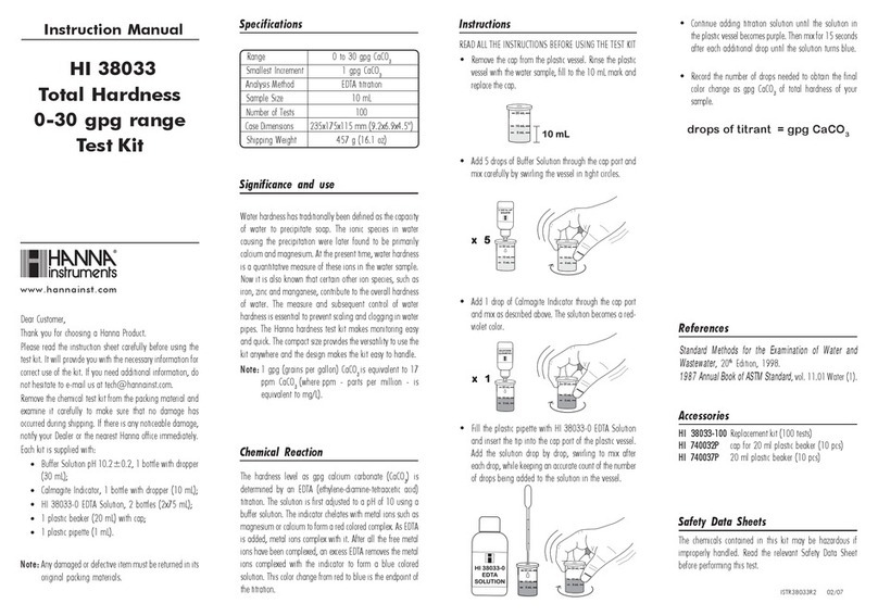
Hanna Instruments HI 38033 instruction manual

