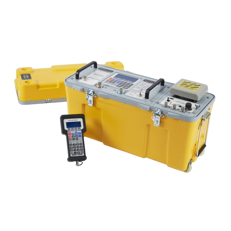
GE MicroVersaTrip TVTS1 User manual

For Field Testing
MicroVersaTrip"
Solid-state
Programmers
GEK·64464B
8;
MicroVersaTripe
Test Set
Type
TVTS1
J (
'ldL
. ,
I
,
".'
;'.'
. .
.....
;
..
;
~--~'"
.,,,/
,'-...--
GENERAL
(I
ELECTRIC


Table
of Contents
Contents
Page
INTRODUCTION.....
..
.............................
3
Testing
ttw
Solid-state
Prog
rammer
Only-Mode
"1"
..
. 3
Testing
the
Complete
Trip
System-Mode
"2"
.......
3
APPLICABLE
TIME-CURRENT
CURVES
.............
3
SPECiFiCATIONS
...................................
3
OPERATING
CONTROLS
............................
4
On-Off
Switch.
..
.
...
.
...
. .
...
...
. .
..
.
..
. .
..
..
.....
4
Trip
Breaker-Programmer
Only
Switch
..........
'"
4
Preset
Current
Button
...........................
'"
4
Start
Button
....................................
'"
4
Reset
Button
...................
'"
..............
" 4
Trip
Light.
...
. . .
....
.
..
........
.
...
. . .
....
........
4
Programmer
Type
Switch
..........
,
..
...
..
...
.....
4
Programmer
Current
Setting
Switch
................
4
Test
Selector
Switch
.............................
" 4
Component
Test
Selector
Switch
................
'"
5
Sequence
Switch
......
" .
...
.
........
......
.....
..
5
Push
to
Test
Button.....
. .
..
..
. . .
...
. . .
............
5
Elapsed
Time
Meter
.............
"
..
..
. . .
...
..
.....
5
Test
Current
Meter..
..
....
. . . .
....
......
.....
.
.....
5
Output
Jacks
J1
and
J2
............................
5
External
Monitor-Test
Set
Accuracy..
..
. .
..
.......
5
HOW
TO
REMOVE
THE
SOLID-STATE
PROGRAMMER
FOR
TESTING
..................................
5
CONNECTING
THE
TEST
SET.......................
6
Safety
Precautions
................................
. 6
Connections
......................................
6
Programmer
Only
Test-Mode
"1"
. .
..
.
...
.
.........
6
Complete
System
Test-Mode
"2"
..................
7
PRELIMINARY
TEST
PROCEDURE...................
8
FUNCTIONAL
TESTS
................................
8
Long
Time
Pickup
Test.............................
8
Long
Time
Delay
Test
...........................
'"
9
Short
Time
Delay
Test
.............................
10
Short
Time
Pickup
Test
............................
12
Instantaneous
Pickup
Test-Standard
...............
13
Instantaneous
Pickup
Test-High
Level
.............
14
Ground
Fault
Pickup
Test
..........................
15
Ground
Fault
Delay
Test
...........................
16
Ground
Fault
Continuity
Test
.....................
" 17
Converter
Check
Test
..............................
18
COMPONENT
TESTS
................................
19
Zone
Interlock
Transmit
Test.,
...
,
....
,
..
,
........
, 19
Short
Time
Transmit
Test
..
,.,
...
,',."
...
,
......
19
Ground
Fault
Transmit
Test
..............
,
.....
,.
19
Open
Diode
Test
.......
"
..
,
....
".,
..
,
..
"
..
,
...
, 19
Shorted
Diode
Test
...
,
....
"
..
,
..............
,
....
19
Sensor
Continuity
Test.,
....
,
..................
,
...
19
FAULT
TRIP
ANNUNCiATORS.,
....
,.,
............
,.
20
HOW
TO
USE
THE
"EXTERNAL
MONITOR"
..........
20
IF
RESULTS
DO
NOT
CONFORM
...........
,'
...
,'
,.21
COMPLETION
OF
TESTS
.................
,
...
"
.....
21
RECORD
OF
ORIGINAL
"IN
SERVICE"
PROGRAMMER
SETTINGS
AND
NOTES.,
....
,
,.
22
SCHEMATIC
DIAGRAM......
..
..................
23
2
These
instructions
do
not
purport
to
cover
all
details
or
variations
in equi
pment
nor
do
they
provide
for
every
possible
contingency
to be
met
in
connection
with
installation,
operation
or
maintenance.
Should
further
information
be
desired,
or
should
particular
problems
arise
which
are
not
covered
sufficiently
for
the
purchaser's
purpose,
the
matter
should
be
referred
to
the
General
Electric
Company.
(
("
..
4,::'··::",
~.

(
€i
"
..
..
'
.-
';
~
Introduction
The Type TVTS1 Test Set is a portable
instrument
de-
signed for the field
testing
of MicroVersaTrip'" solid-state
programmers. The
complete
trip system is
comprised
of
the
following
components:
1
Solid-state
programmer
2.
Phase
Current
Sensors
3.
Flux
Shift
Magnetic
Trip
Device
4.
When
applicable,
a Neutral
Sensor
for
units
containing
a
Ground
Fault
trip
element.
All
components,
except
the Neutral Sensor, are
integrally
mounted
in the
circuit
breaker. When used, the Neutral Sen-
sor
is separately
mounted
in the bus
or
cable
compartment
of
the
switchgear.
In
drawout
construction,
it is
automati-
cally
connected
to
the
programmer
in the
breaker
via a
drawout
secondary
disconnect
block.
Two
basic types of
solid-state
programmers
will
be
tested. See Fig. 1.
The Test Set is used to
perform
various
programmer
tests
in
two
basic
modes:
Testing the
Solid-state
Programmer
Only-Mode
"1"
Testing
the
Complete
Trip
System-Mode
"2"
WARNING:
THESE TESTS
CAN
BE
CONDUCTED
ONL
Y
ON
A
DE-ENERGIZED
BREAKER-ONE
WHICH
IS
COMPLETEL
Y
DISCONNECTED
FROM
ITS
PRIMARY
AND
CONTROL
POWER
SOURCES.
-.~-
..
---.u
.-
:=.
-=
,~
e!!!!!!'=======
•
.•
~
-'-
.,,,
..
.,
-.
-""
--'
¢ •
-'
•
r;
MicroVersaTrip®
TP4VT, TP9VT,
TAVT programmers
Fig_
1
MicroVersaTrip®
T4VT
programmer
Testing the Solid-state Programmer
Only-Mode
"1"
A test
mode
is
used
where
only
the
solid-state
program-
mer is tested,
and
is
particularly
useful
in
testing
spare
or
alternate
programmers.
It
should
be
noted
however,
that
there
can be
no
substi-
tute
for
complete
testing
of
the
trip
system
per
Mode
"2".
See Fig.
5.
Since
the
programmer
is
only
a
part
of
the
com-
plete
trip
system,
the
PROGRAMMER
ONLY
tests
should
be
recognized
as
only
a
partial
system test.
Test
Scope
1.
Verify the
time-current
characteristics
and
pickup
cali-
bration
of
the
various
trip
elements.
Designations
for
the
trip
elements
are
abbreviated
as
fol-
lows:
LT
-LONG
TIME
INST.-INSTANTANEOUS
ST
-SHORT
TIME
GF-GROUND
FAULT
2.
Verify
performance
of
the ZONE SELECTIVE INTER-
LOCKING
functions
on
programmers
so
equipped.
3.
Verify the
integrity
of
key
electronic
components
in
the
solid-state
programmer.
4.
Verify
operation
of
the
Fault
Trip
annunciators
on
pro-
grammers
so
equipped.
Testing the
Complete
Trip
System-
Mode
"2"
For these tests,
the
programmer
is
connected
to
the
breaker
through
the test set.
Test
Scope
1.
All
programmer
tests
previously
described,
plus
the
provision
to
optionally
switch
the
programmer's
output
to
activate the
Flux
Shift
Magnetic
Trip
Device
to
verify its
op-
eration
by
physically
tripping
the
breaker.
2.
Check
continuity
of
the Phase
Sensors
.
Applicable Time-current
Curves
GES
6198-Four-function
(T4VT; TP4VT)
MicroVersaTrip'" :
LT;
ST; INST.
GES
6199-Full-function
MicroVersaTrip'" :
LT;
ST;
INST,
GES
6195-Ground
Fault
Specifications
Input:
105-125 Vac, 50/60 Hz
Power
Consumption:
60
Watts
Weight:
30
Pounds
Overall
Dimensions
(Inches): 22% L x 12% W x 9'/8 H
3


Operating Controls (See Fig. 2)
ON-OFF
Switch
This
switch
applies
115-Vac
input
power
to
the
test
set
when
the
switch
is ON.
Protection
is
provided
by
a
one-
ampere
fuse
located
above
the
ON-OFF
switch.
TRIP
BREAKER-PROGRAMMER
ONLY
Switch
•
PROGRAMMER
ONLY
Position
The
programmer's
trip
signal
is
confined
to
the
test set
circuitry
and
cannot
trip
the
breaker
•
TRIP
BREAKER
Position
The
programmer's
trip
signal
is
directed
to
the
circuit
breaker's
magnetic
trip
device
to
physically
trip
the
breaker.
This
mode
establishes
the
integrity
of
the
magnetic
trip
de-
Vice
and
the
programmer's
ability
to
actuate
it.
PRESET
CURRENT
Button
This
button
enables
the
operator
to
pre-establish
(via
the
TEST
CURRENT
ADJUST
control)
the
desired
test
current
prior
to
initiating
a test.
START Button
Tills
button
Initiates
the
test
by
applying
current
to
the
programmer.
The
current
persists
until
the
unit
trips
or
the
RESET
button
IS
actuated
• _
•.
',"0
'.
RESET Button
This
button
resets
the test
set
logiC so
that
a
new
test
sequence
can be
initiated.
It
also
stops
a test In
progress.
TRIP Light
This
LED.
when
lit,
indicates
that
a
trip
signal
has
been
delivered
by the
programmer.
A
trip
indication
will
always
be
accompanied
by a
brief
audio
tone.
PROGRAMMER
TYPE Switch
This
switch
is
to
be
positioned
according
to
the
program-
mer
type
which
is
normally
determined
from
th()
program-
mer
Cat. No. If
there
is
any
question
as
to
whether
the
programmer
is
Type
A
or
B,
it
can
be
answered
by
running
the
CONVERTER
CHECK.
(See
page
18).
PROGRAMMER
CURRENT
SETTING
Switch
This
control
establishes
a
test
current
magnitude
consis-
tent
WI
til
and
specifically
for
each
CURRENT
SETTING
of
the
programmer.
The
position
of
this
control
must
match
the
setting
on
the
programmer
when
testing
the LT
and
ST
ele-
ments
TEST SELECTOR Switch
This
selector
is
to
be
positioned
according
to
the
type
of
test to be
run
Associated
with
the TEST
SELECTOR
is a
grouping
of
toggle
switches
and
a
rotary
switch
which
fur-
ther
break
down
the
major
tests
into
specific
test
options
.
"·:l
"_~'.!
-;,::~:-~
Fig.
2.
Front
panel
(


Operating Controls (See Fig. 2)
COMPONENT
TEST
SELECTOR
Switch
This
switch
becomes
active
when
the
TEST SELECTOR is
in
the
COMPONENT
TESTS
position.
The
switch
selects one
of
several
auxiliary
tests
that
are
necessary
for
complete
testtng
of
the
programmer.
SEQUENCE
Switch
This
switch
directs
the
test
signals
to
various
points
in
the
programmer
circuitry.
PUSH TO
TEST
Button
A
push
button
switch
which
initiates
each
of
the
compo-
nent
tests,
resulting
in
illumination
of
the
"OK"
LED
indica-
tor
when
a
satisfactory
test
result
is
achieved.
Failure
of
the
"OK"
indicator
to
light
signifies
an
unsatisfactory
test result.
ELAPSED
TIME
Meter
This
meter
is a
counter
which
records
the
programmer's
trip
time
in
seconds
and
tenths.
It
must
be
manually
reset
after
completion
of
each
test. The
accuracy
of
the
timer
is
one
digit:':
O.
t
second.
NOTE:
When
operating
the
test
set
from
a 50-Hz
supply,
readings
of
the
ELAPSED
TIME
meter
must
be
multiplied
by
1.2.
TEST
CURRENT
Meter
This
meter
provides
digital
readout
of
the
magnitude
of
the test
current
be'tng
applied
to
the
programmer.
TEST
CURRENT
ADJUST
This
device
is a
high-resolution
ten-turn
potentiom-
eter used
to
vary
the
TEST
CURRENT
applied
to
the
programmer.
Output
Jacks
J1
& J2
Jack
J1
connects
to
the
circuit
breaker
via
the
circuit
breaker
INTERFACE
MODULE
A
or
B
which
is
provided.
Jack J2
connects
to
the
programmer
via
the
eight-foot
jumper
cable
provided.
EXTERNAL
MONITOR-Test
Set
Accuracy
The test
current
values
displayed
on
the
TEST CURRENT
meter
are
accurate
to
within:':
three
percent
of
the
meter
reading. These
limits
are
contingent
upon
a clean sine-wave
input
voltage
to
the
test set. Wave
form
distortion
can
cause
additional
errOr.
Should
greater
accuracy
be
desired,
provision
is
made
for
connecting
external
instruments
via
the
EXTERNAL MONI-
TOR
jacks
on
the
front
panel.
The
EXTERNAL
MONITOR
jacks
may
be used to
check
calibration
of
the
instrument
and
to
measure
trip
times
of
less
than
ten
seconds
more
accurately.
See Table
9,
Page 20
entitled,
"HOW
TO
USE THE EXTERNAL
MONITOR."
How
to~
Remove the Solid- state Programmer for Testing
MicroVersaTrip® Programmers
Cat. No. T4VT
1.
Push
the
"PUSH
TO
TRIP"
button
on
the
front
of
the
circuit
breaker.
2.
Remove
the
cover
protecting
the
Micro-VersaTrip'
programmer.
3.
Carefully
remove
the
two-pin
flux
shifter
trip
coil
connector.
4.
Loosen
completely
the
two
captive
screws
that
secure
the
programmer
to
the
sensor
package
The
programmer
may
now
be
removed
MicroVersaTrip® Programmers
Cat. No. T9VT
1 Push
the
"PUSH
TO
TRIP'
button
on
the
front
of
the
circuit
breaker.
2.
Remove
the
cover
protecting
the
Micro-VersaTrip!
programmer.
3.
Depress
the
locking
lever
on
the
side
of
the
program-
mer
plug-in
base
and
remove
the
programmer,
4.
Follow
the
instructions
on
the
back
of
the
programmer
to
complete
removal.
MicroVersaTrip® Programmers Used
with Type AKJAKRlAKD Circuit
Breakers
Simply
remove
the
programmer
by
gently
removing
it
from
its
plug-In
base. In
some
breakers,
this
will
require
the
re-
moval
of
two
mounting
screws:
In
others,
it
will
be neces-
sary to
depress
the
locking
lever
on
the side
of
the
programmer
plug-in
base.
5


How to
Remove
the Solid- state Programmer for Testing
MicroVersaTrip® Programmers Used
with Small Frame POWER
BREAK®
Circuit
Breakers-
Frame Size
2000 Amperes or Less
(Programmer Types TP4VT20 and
TP9VT20)
Breaker
Without the Electrical
Operator
Accessory
1.
Push
the
"OFF"
button
on
the
front of
the
circuit
breaker.
2.
Remove
the
four
top
cover
screws
and
remove
the
cover
from
the
breaker.
The
programmer
is
now
readily
accessible.
3.
To
remove
the
programmer,
release
the
cover
interlock
and
remove
the
programmer
from
its
plug-in
base
with
a
gentle
rocking
motion.
Breakers
with the Electrical
Operator
Accessory
1.
Push
the
"OFF"
Button
on
the
front of
the
circuit
breaker
Connecting the Test Set
Safety
Precautions
6
WARNING:
BEFORE
CONNECTING
THE TEST
SET
TO
THE
BREAKER,
ENSURE
THAT
THE
CIR-
CUIT
BREAKER
IS
COMPLETEL
Y
DISCON-
NECTED
FROM
ITS
POWER
SOURCE.
ON
DRAWOUT
EQUIPMENT,
RACK
THE
BREAKER
TO
ITS
DISCONNECTED
POSIT/ON.
VERIFY
THAT THE
BREAKER
IS
OFF.
CAUTION:
NEVER
DISENGAGE
THE
PRO-
GRAMMER
ON
A
BREAKER
THAT IS
ENER-
GIZED
AND
CARRYING
LOAD
CURRENT.
THIS
WILL
OPEN-CIRCUIT
THE
CURRENT
SENSORS,
ALLOWING
DANGEROUS
AND
DAMAGING
VOLTAGES
TO
DEVELOP.
SEE
FIG.
3.
2.
Remove
the
four
top
cover
screws
and
remove
the
cover
from
the
circuit
breaker
3.
To
remove
the
programmer,
release
the
cover
interlock
and
remove
the
programmer
Irom
its
plug-in
base
with
a
gentle
rocking
motion.
MicroVersaTrip® Programmers Used
with Large Frame POWER BREAK®
Circuit
Breakers-
Frame Size 3000
Amperes or More. (Programmer
Types TP4VT25; TP4VT30; TP9VT25;
TP9VT30; TP9VT40)
With or Without the Electrical
Operator
Accessory
1.
Push
"OFF"
button.
2.
Remove
four
screws
holding
the
escutcheon
cover
over
the
programmer.
Remove
the
escutcheon
cover.
3.
Remove
the
four
remaining
screws
and
remove
the
cover
from
the
circuit
breaker
4.
To
remove
the
programmer,
release
the
cover
interlock
and
remove
the
programmer
from
its
plug-in
base
with
a
gentle
rocking
motion.
Connections
"PROGRAMMER
ONLY"
Test-Mode
"1"
(See
Fig, 4)
Remove
the
programmer
from
the
circuit
breaker.
2
Connect
the
test set
to
the
programmer
as
follows:
a.
For
the
four-function
Cat. NO.T4VT
programmer
housed
in a
plastic
shell,
plug
the
programmer
directly
into
the
space
provided
on
the
front
panel
of
the
test set.
b
For
all
other
programmers,
connect
one
end
of
the
eight-fool
female
(sockets)
connector
cable
to
the
programmer
and
the
other
end
10
connector
J2
of
the
test set.
3 It is
not
necessary
to
make
any
connection
to
the
cir-
cuit
breaker
for
"PROGRAMMER
ONLY"
testing.
The
Fig. 5
connection
must
be used
if
"COMPLETE
SYSTEM"
tests are
to be run.
~:.'
,


,0
Connecting the Test Set
c;::::;::J
y:y
y:y
~
I."
~I_J:
[[ 1
~~)J
Micro-VersaTrip"' T4VT
Programmer
and
Sensor
Package
FRONT VIEW
?===--
Breaker
Harness
to
Current
Sensors
and
Magnelic
Trip
Device
All
Other
Micro-VersaTrip'
Programmers
SIDE VIEW
Fig.
3.
Normal
in-service
breaker
connection
All
Other
Micro-VersaTrip'
Programmers
Micro-VersaTrip"
Test Set
b b 6 a
Micro-VersaTrip"
T4VT
Programmers
~
Plug
In
Here
Fig. 4.
Connection
for
"PROGRAMMER
ONLY"
test
"COMPLETE
SYSTEM"
Test-Mode
"2"
(See
'Fig.
5)
1,
Connect
the
test set
to
the
programmer
as
described
in
Step
2
of
Mode
"1"
("PROGRAMMER
ONLY"
Test)
discussed
previously,
2,
Connect
the
test
set
to
the
circuit
breaker
as
follows:
a
For
circuit
breakers
utilizing
the
four-function
Cat.
No,
T4VT
programmer,
plug
Micro-VersaTrip':
TEST
SET
INTERFACE
MODULE
B
into
the
sensor
pack-
age,
Make
sure
to
plug
the
two-pin
flux-shifter
trip
coil
connector
into
the
interface
module,
Tighten
the
two
captive
retaining
screws
and
plug
the
interface
module
cable
connector
into
test
set
connector
J1,
Circuit
Breaker
All
Other
Micro-VersaTrip'
Programmers
Micro-VersaTrip'
Trip
Test Set
b b 6 a
Mlcro-VersaTrip"
T4VT
Programmer
t
Plug
In
Here
Fig,
5,
Connection
for
"COMPLETE
SYSTEM"
Test
b,
For
all
other
circuit
breakers,
plug
Micro-VersaTrip'"
TEST
SET
INTERFACE
MODULE
A
into
the
circuit
breaker
base
plate,
Connect
the
cable
from
the-
in-
terface
module
to
test
set
connector
J1,
NOTE:
If
the
circuit
breaker
has
a
cover
interlock
mechanism
such
as
in
Power-Break"
circuit
breakers,
it
will
be
necessary
to
install
the
circuit
breaker
cover
to
close
the
breaker,
This
means
that
the
connector
cable
from
the
interface
mod-
ule
must
be
routed
through
the
programmer
win-
dow
in
the
cover
before
the
cover
is
applied,
7


Preliminary Test Procedure
The
following
procedure
should
be
followed
before
start-
ing
functional
tests.
1.
Position
the test set
controls
as
follows:
a.
TRIP
BREAKER-PROGRAMMER
ONLY
Swilch
as
desired.
b.
PROGRAMMER
TYPE
Switch-Position
per
pro-
grammer
type
(A
or
B).
c.
PROGRAMMER
CURRENT
SETTING-Must
match
the
programmer
current
satting.
Functional Tests
d. TEST
SELECTOR-Long
Time/Short
Time.
e.
TEST CURRENT ADJUST
-Completely
counter-
clockwise.
2.
Record
the
"IN
SERVICE"
settings
of
the
programmer
so
that
these set
poinls
can
be
restored
upon
completion
of
testing.
See page
22.
3.
Connect
the test set
power
cord
to the 105-125-Vac
power
source.
4.
Turn
power
switch
"ON".
NOTE:
In
using
the
test
set,
it
is
never
necessary
to
calculate
test
current
values.
If
the test
set
and
programmer
controls
are
set
as
described
for
each
of
the
functional
tests
on
the
following
pages,
the
TEST
CURRENT
value
will
correspond
to
programmer
face
plate
values. (e.g.
the
meter
will
read
1.50
for
a
SHORT
TIME
PICKUP
of
1.5C
or
for
an
INSTANTANEOUS
PICKUP
of
1.5X
etc.)
LONG
TIME
PICKUP
Test
Purpose
Verify
that
pickup
occurs
within
tolerance.
Each
program-
mer
is
equipped
with
a
convenient
LED LONG TIME PICKUP
light
permitting
a
straight
forward
visual
means
of
determin-
ing
when
the LONG
TIME
PICKUP
point
is reached.
Test
Procedure
1.
Programmer
Settings:
LONG TIME PICKUP (if
present)-1.1C
2.
Position
Test
Set
Controls:
PROGRAMMER
CURRENT
SETTING-Must
match
the
programmer's
CURRENT
SETTING
TEST
SELECTOR-Long
Time
3.
TEST CURRENT
-Preset
a TEST CURRENT of 0.95
4.
Push START
Table
1-Long
Time
Pickup
Long
Time
Pickup
Settings
Test
Current Limits
O.BC·
0.70-0.91
o
9C'
0.79-1.02
1.0C·
0.B7-1.13
1.1C
0.96-1.25
~----.
'These
values
applicable
only
to
programmers
with
the
adjustable
LONG
TIME PICKUP
option
5.
Slowly
increase the TEST CURRENT,
carefully
observ-
ing
the
LONG TIME PICKUP
light
on
the
programmer.
The
light
will
indicate
when
the
pickup
point
is reached.
6.
Read
the
TEST CURRENT value at
which
pickup
oc-
curs
and
compare
with
the
acceptable
limits
of
Table 1
(1.1
C
setting).
7.
If'the
programmer
is
equipped
with
an
adjustable
LONG TIME PICKUP, repeat
the
above test at 0.8C,
O.9C
and
1.0C.
IF TEST
RE5UL
T5
DO NOT
CONFORM,
SEE PAGE
21
8
,.
~;_\


LONG
TIME
DELAY Test
Purpose
Verify
that
the
LT
characteristic
conforms
to
its
upper
and
lower
band
limits.
It is
recommended
that
measurements
be
taken at
three
different
values
of
TEST CURRENT
Test
Procedure
1.
Programmer
Settings:
SHORT
TIME
PICKUP
{If
present)-9C.
2.
Position
Test
Set
Controls:
PROGRAMMER
CURRENT
SETTING-Must
match
the
programmer's
CURRENT
SETTING.
TEST
SELECTOR-Long
Time.
TEST
CURRENT-From
Table
2
(using
proper
Table
2A
or
28),
select
three
test
current
values. Preset the first
value.
NOTE:
These
values
must
be
below
the
program-
mer's
SHORT
TIME
PICKUP
setting,
otherwise,
a
premature
trip
signal
will
be
received
from
that
function.
3.
Reset
timer
and
push
RESET
button.
4. Push START.
Allow
test
to
run
until
trip
occurs.
The
trip
time
should
conform
to
Table
2
limits.
For
50-Hz
opera-
tion,
multiply
timer
readings
by 1.2.
5.
Repeat
the
above
test
at
two
other
TEST CURRENT
values.
6.
If
the
programmer
is
equipped
with
adjustable
LONG
TIME
DELAY
bands,
repeat
the
above
test series on
the
other
delay
bands
(Table
28).
Table
2A-T4VT
and TP4VT (Four-
function) Programmers with Fixed
(Non-adjustable) Delay Band
Trip-Time
Test
Limits
(In
Seconds)
Current
Min
Max
1.50 209.7 353.7
2.00 117.6 198.2
3.00 51.8 87.3
4.00 29.0 48.8
5.00 18.3 30.8
6.00 12.7 21.4
7.00 9.3 15.7
8.00
7.1
12.0
Table
2B-Programmers
with Adjust-
able Long Time Delay Bands
Programmer
Trip-Time
"long
Time
limits
(In SecondsO)
Delay"
Test
Setting
Current
Min
Max
1.50 37.3 62.7
2.00 20.9 35.3
3.00 9.2 15.6
1 4.00
5.1
8.8
5.00 3.3 5.5
6.00 2.3 3.9
7.00 1.7 2.8
8.00 1.3 2.2
1.50 74.9 126.0
2.00 41.9 70.7
3.00 18.6 31.2
2 4.00 10,4 17.5
5.00 6.6
11.1
6.00 4.6 7.7
7.00 3,4 5.6
8.00 2.6 4.3
1.50 150,4 253.4
2.00 84.3 141.9
3.00 37.2 62.6
3 4.00 20.8
35.1
5.00 13.2 22.2
6.00
9.1
15.4
7.00 6.7 11.3
8.00
5.1
8.7
1.50 314.9 530.4
2.00 176.5 297.2
300
77.7
131.0
4 4.00 43.5 73.3
5.00 27.4 46.2
6.00
19.1
32.1
7.00 14.0
236
8.00 10.7
18.1
"Reflecting
the
-:-
3%
test set
accuracy.
allIes!
lim'lls are
extended
beyond
the
published
band
limits
of
the
lime-current
curves.
DUring
testing.
the
test
cur-
rent
should
be
monitored
and
readjusted
If
necessary
~~~_I~
TEST
RESULTS
DO
NOT
CONFORM,
SEE
PAGE
21
9


SHORT
TIME
DELAY Tests
Purpose
To test the ST
delay
functions.
There
are
two
possible
ST
delay
tests Test
No.1,
for
full-function
programmers,
checks
the
three
fixed-time
delay
bands
(MIN, INT, MAX).
Test
No.2
checks
the
Short
Time
I't
functions
when
present
(standard
for
four
function
T4VT and TP4VT
programmers;
optional
for
all
other
programmers).
It
should
be
noted
that
the
accu
racy
of
the
test sets
in
SECONDS
is "'
the
last
digit
(:':
0.1
second).
If a
more
accurate
reading
is
desired,
the
EXTERNAL
MONITOR
jacks
may
be
used
to
determine
the
exact
programmer
trip
time.
See
page
20
Before
beginning
this
test, it is
necessary
to
determine
whether
the
programmer
being
tested
is
equipped
with
ZONE
SELECTIVE
INTERLOCKING.
This
can
be
determined
by
noting
whether
there
is a Z
suffix
in
the
programmer
cat-
alog
number.
Another
method
is
to
connect
the
programmer
to
the
test set
and
turn
the
TEST
SELECTOR
to
the
LONG
TIME/SHORT
TIME-ZONE
INTERLOCKED
position.
If
the
"ZONE
INTERLOCKED"
light
is lit.
the
function
is
present.
Test
Procedure
TEST
NO,
1-TESTING
THE
SHORT
TIME
DELAY-
FIXED
TIME
DELAY
BANDS
(NOT
APPLICABLE
TO FOUR-
FUNCTION
T4VT
AND
TP4VT
PROGRAMMERS).
1.
Programmer
Settings:
CURRENT
SETTING-l.0
SHORT
TIME
PICKUP-l.SC
SHORT
TIME
I't
Switch
(if
present)-"OUT"
2.
Position
Test
Set
Controls:
PROGRAMMER
CURRENT
SETTING-l.0
TEST
SELECTOR-LONG
TIME/SHORT
TIME-Stan-
dard
3.
TEST
CURRENT
-Preset
a value
of
3.00
4.
Reset
timer
and
push
RESET
button.
5.
Push
START
-A
TRIP
light
must
be
obtained.
Observe
trip
time.
NOTE:
It
is
important
to
observe
that
the
time
delay
will
be
dependent
on
whether
or
not
the
programmer
being
tested
is
equipped
with
ZONE
SELECTIVE
INTERLOCKING.
It is,
therefore,
im-
portant
to
select
the
proper
Table (3A
or
38).
Test all
three
delay
bands
(MIN, INT, MAX)
For
50-Hz
op-
eration,
multiply
the
timer
reading
by 1.2.
6.
If the
programmer
is
equipped
with
the
ZONE INTER-
LOCKED
Option,
continue
by
testing
as
follows:
10
a.
Position
the
TEST
SELECTOR
in the SHORT
TIME-
ZONE
INTERLOCKED
pOSition.
The
test
set SHORT
TIME-ZONE
INTERLOCKED
light
must
come
on.
b.
Repeat
Steps
3
through
5.
TEST
NO.
2-
TESTING
THE
SHORT
TIME
1'1
FUNCTION
(IF
PRESENT)
(STANDARD
FOR
FOUR-FUNCTION
T4VT
AND
TP4VT
PROGRAMMERS).
1.
Programmer
Settings:
CURRENT
SETTING-1.0
SHORT
TIME
PICKUP-l.SC
SHORT
TIME
I't
Switch
(if
present)-"IN"
2.
Position
Test Set
Controls:
Same
as Test
No.1
3.
TEST
CURRENT-Preset
one
of
the
TEST
CURRENT
values
shown
in
Table
3C.
4. Reset
the
timer
and
push
the
RESET
button.
5.
Push
START.
Observe
trip
time.
a.
Repeat
using
the
other
TEST
CURRENT
values in
Table
3C
6.
The
following
note
is
applicable
only
to
full-function
MicroVersaTrip®
programmers.
NOTE:
To
avoid
confusion,
the
TEST
CURRENT
is
limited
to
the
values
in Tabfe 3C.
If
it
is
desired
to
test
at
higher
levels,
it
shoufd
be
noted
that
the
I't
curve
is
valid
only
to
the
point
where
the
I't
curve
intersects
the
ST
fixed
delay
bands.
At
this
point,
the
fixed
curves
take
precedence.
Note
also
that
if
the
programmer
is a
ZONE
SE-
LECTiVE
INTERLOCK
model,
the
ST
delay
will
al-
ways
be
"MIN"
(regardless
of
the
programmer
ST
delay
setting)
until
a
zone
interlock
signal
is
received
at
which
time,
the
delay
band
becomes
the
programmer
ST
delay
setting.
This
will
shift
the
intersect
point
of
the
I't
and
fixed
delay
curves.

Table of contents
Other GE Test Equipment manuals