TECALEMIT DE9419 User manual

Tecalemit
DE9419/DE9719
User Manual
Document number: 318469
Rev: 00
Date: 2019-01-01

2

Copyright
Copyright © 2019 Tecalemit Garage Equipment. All rights reserved worldwide.
All of the information in this manual and any drawings and technical descriptions which have
been made available by us, remain our property and may not, without first obtaining written
permission from Tecalemit Garage Equipment, be used (except for operating the machine),
duplicated in any way, handed over or made known to a third party.
Disclaimer
All efforts have been made to ensure the accuracy of this manual. However, should any
errors be detected, Tecalemit Garage Equipment would greatly appreciate being informed of
them. The above notwithstanding, Tecalemit Garage Equipment cannot assume any
responsibility for any errors in this manual or their consequences.
The information contained in this document is subject to change without notice and does not
represent a commitment on the part of the copyright holder. The software, associated
hardware and documents are furnished under license agreement. The software, associated
hardware and documents may be used only in accordance with the terms of that agreement.
Contact details:
Tecalemit Garage Equipment
Eagle Road, Langage Business Park,
Plymouth, PL7 5JY
United Kingdom
Phone: +44 (0)1752 219 111 (Sales), +44 (0)1752 219 100 (Service)
Fax: +44 (0)1752 219 128 (Sales & Service)
Website: www.tecalemit.co.uk
E-mail: sales@tecalemit.co.uk, service@tecalemit.co.uk
CE Regulation Compliance
The product complies with all applicable CE directives (see “Declaration of conformity to CE
directives" on page 48).
3

Contents
Contents...............................................................................................................................4
Chapter 1 About this manual..............................................................................................6
Audience............................................................................................................................6
Scope.................................................................................................................................6
Organisation.......................................................................................................................6
Availability of this manual...................................................................................................6
Chapter 2 Introduction........................................................................................................7
Introduction.........................................................................................................................7
Chapter 3 Safety..................................................................................................................8
General safety instructions.................................................................................................8
System safety features.......................................................................................................9
Chapter 4 Specifications .................................................................................................10
DE9419-MOT...................................................................................................................10
DE9419-ATL with weighing system..................................................................................10
DE9719-MOT...................................................................................................................11
DE9719-ATL.....................................................................................................................11
Chapter 5 Functional description....................................................................................12
Floor modules...................................................................................................................12
DE9419/DE9719 brake tester......................................................................................12
Weighing system..........................................................................................................13
Console............................................................................................................................14
Software...........................................................................................................................14
General layout of the start screen................................................................................15
General layout of the test lane screens........................................................................16
General layout of the test lane screens (continued).....................................................17
Test screen overview...................................................................................................18
Remote control.................................................................................................................19
Navigate using the remote control or keyboard............................................................19
Chapter 6 Vehicle/customer data.....................................................................................20
Add a new vehicle to the database...................................................................................20
Specific Class 4...........................................................................................................21
Specific Class 7...........................................................................................................21
Specific Class 5L.........................................................................................................21
Specific Class 3...........................................................................................................21
Add a new customer.........................................................................................................22
Assign a customer to a vehicle.........................................................................................22
Add a vehicle to the test queue.........................................................................................22
Remove vehicle or customer data....................................................................................23
Select a vehicle from the test queue.................................................................................23
Chapter 7 Operating instructions; preparations.............................................................24
Operator safety.................................................................................................................24
Start up the test lane/shut down the test lane...................................................................24
Emergency stop................................................................................................................25
4

Start up after an emergency stop......................................................................................25
Preparations before starting a brake test..........................................................................25
Chapter 8 Operating instructions; manual mode...........................................................26
Quick manual test mode Class M1, 4, 5L, 7.....................................................................26
Perform a test..............................................................................................................27
Manual test mode Class M1, 4, 5L, 7...............................................................................31
Perform a test..............................................................................................................31
Manual test mode class 3 (tested as Class 4)..................................................................32
Manual test mode 4WD selectable ..................................................................................33
Manual mode class 1 & 2.................................................................................................35
Specific Class 1 & 2.....................................................................................................35
Perform a test..............................................................................................................35
Chapter 9 Operating instructions; ATL mode.................................................................38
ATL mode.........................................................................................................................38
Weight measurement...................................................................................................38
Perform a test..............................................................................................................39
Chapter 10 Analyse, print, save and review results.......................................................41
Analyse the test results.....................................................................................................41
Print test results................................................................................................................42
Save test results...............................................................................................................42
Review test results from earlier tests (Report)..................................................................43
Chapter 11 General settings.............................................................................................44
General settings Test tab..................................................................................................44
General settings General tab............................................................................................45
General settings Limits Tab..............................................................................................45
Chapter 12 Troubleshooting.............................................................................................46
Troubleshooting tables.....................................................................................................46
Chapter 13 Preventive maintenance................................................................................47
Maintenance safety..........................................................................................................47
Maintenance schedule......................................................................................................47
Chapter 14 Declaration of conformity to CE directives..................................................48
5

Chapter 1 About this manual
In This Chapter
Audience 6
Scope 6
Organisation 6
Availability of this manual 6
Audience
This user manual is intended for persons who operate the DE9419/DE9719 brake tester.
Tecalemit Garage Equipment requires that these operators:
Have sufficient technical knowledge and experience to do the assigned tasks.
Can recognize and prevent hazards.
Have read and understand this manual.
Have been correctly trained.
Follow the procedures in this manual.
Scope
The purpose of this manual is to:
Describe the operation of the system.
Describe its operating principles and general construction.
Explain safety features and safety precautions.
Highlight possible hazards.
Describe procedures to operate the system.
Describe solutions to system problems.
Organisation
This user manual contains the following chapters:
Introduction (on page 7): contains a short description of the system.
Safety (on page 8): describes safety features on the DE9419/DE9719 brake tester and
safety precautions to obey when you operate or do work on the system. Read this section
before installation, operation and maintenance.
Specifications (on page 10): contains specification of the DE9419/DE9719 brake tester.
Functional description (on page 12): contains a functional description of the
DE9419/DE9719 brake tester.
Vehicle/customer data (on page 20): contains all procedures necessary to operate the
vehicle/customer section of the DE9419/DE9719 brake tester program.
Operating instructions (chapters 7, 8 and 9): contains all procedures necessary to
operate the DE9419/DE9719 brake tester safely.
Chapter 10 describes how to analyse, print, save and review test results.
General settings (on page 44): describes general settings for the test lane.
Troubleshooting (on page 46): contains procedures to solve problems encountered
operating the DE9419/DE9719 brake tester and lists error messages.
Preventive maintenance (on page 47): contains maintenance procedures that can be
done by the operator.
Availability of this manual
Tecalemit Garage Equipment expects a copy of this manual to be available to the user.
6

Chapter 2 Introduction
In This Chapter
Introduction 7
Introduction
This manual describes how to safely use the DE9419/DE9719 brake tester.
The DE9419-MOT, DE9419-ATL are Class 4 roller brake testers for statutory Vehicle
Inspection of commercially available class 3, 4 and M1 vehicles (herein refer to as MOT
class 3 & 4 & M1).
The DE9719-MOT, DE9719-ATL are Class 7 roller brake testers for statutory Vehicle
Inspection of commercially available class 7 and 5L vehicles (herein refer to as MOT class
7 & 5L).
This manual gives the instructions how to carry out a brake test according to the UK
Department of Transport compulsory schemes. The manual provides the MOT braking
measurement requirements and describes the complete test procedures for both automatic
and manual testing as set out in the MOT inspection manuals current at the time this user
manual was written. Please refer to the latest MOT inspection manual to check for any
changes.
The customer should ensure that the installation for testing vehicles under any of the
Department of Transport compulsory schemes, is according to the details mentioned in the
Department of Transport‘s requirements.
The brake testers are designed in such a way that these can be used in a MANUAL testing
mode as well as an Automatic testing mode (herein refer to as MAN and ATL). The
configuration installed, determines the functionality of the product and if it can be used in ATL
and MANUAL mode, or in MANUAL mode only:
Model
Vehicle
DE9419-MOT DE9419-ATL DE9719-MOT DE9719-ATL
Class 3 MAN MAN MAN MAN
Class 4, Class M1 MAN MAN/ATL MAN MAN/ATL
Class 5L - - MAN MAN/ATL
Class 7 (2 axles) - - MAN MAN/ATL
Class 7 (3 axles) - - MAN MAN/ATL
Class 1 & 2
c/w adapter plate - MAN - MAN
The ATL weighing system is integrated in the brake tester.
7

Chapter 3 Safety
In This Chapter
General safety instructions 8
System safety features 8
General safety instructions
In order to comply with your responsibilities under the Health and Safety at Work Act
1974, it is essential that only properly trained and authorized personnel install, operate
and maintain the brake tester and any optional accessories.
Always follow the instructions in this manual to prevent damage to the machine and
vehicle, and injuries to personnel.
Only properly trained and authorized personnel are allowed to operate and service the
test lane.
Lock the mains switch when the test lane is not in use.
Before you start a test, make sure the safety limit switches on the wheel detection rollers
function correctly. Turn the wheel detection roller and make sure the lights of the
proximity switches come on.
Do not adjust the vehicle brakes or examine tyres when the vehicle is in the rollers.
During the test, make sure nobody stands close to the mechanical units. If necessary,
block accesses or provide a color marking.
Do not remove or short-cut the safety features.
Provide sufficient ventilation or a suitable exhaust suction device when testing with a
vehicle.
The operator is only permitted to do maintenance as described in “Chapter 13 Preventive
maintenance” on page 47.
Do not park a vehicle on any part of the test lane.
Do not stand on, or walk over the rollers at any time.
Do not leave the brake tester switched on and unattended.
Do not test a vehicle when there is insufficient light.
Keep the operating environment clean and free of oil; don’t leave loose objects around
the brake testers.
When the brake tester is not working correctly, switch off the brake tester and refer to the
user manual operations instructions or contact your supplier.
Make sure the remote control is stored safely when not in use.
The equipment may be operated only within its rated capacity.
See “Chapter 4 Specifications” on page 10.
Note
The motor and control gear of the RBT are not flameproof and it is the responsibility of the
operator to make sure that the proposed site and the aspects of the installation comply
with the Petroleum Regulations and that they satisfy the local Petroleum (consolidation)
Regulations 2014.
8

System safety features
The test lane has the following safety features:
Mains switch. The isolator at a dedicated location switches the mains power to the entire
unit off.
Emergency stop button.
The Power button or OK button on the remote control: stops the current test
immediately.
The Enter key on the keyboard: stops the current test immediately.
Roller cover plates to close the roller brake tester when not in use.
9

Chapter 4 Specifications
In This Chapter
DE9419-MOT 10
DE9419-ATL with weighing system 10
DE9719-MOT 11
DE9719-ATL 11
The roller brake testers DE9419-MOT and DE9419-ATL are designed for testing
commercially available class 3 & 4 & M1 vehicles for road use (including 3-wheel vehicles
and 4-wheel driven vehicles).
The roller brake testers DE9719-MOT and DE9719-ATL are designed for testing
commercially available class 7 & 5L vehicles for road use. It is also designed for class 3 & 4
& M1 vehicles (including 3-wheel vehicles and 4-wheel driven vehicles).
DE9419-MOT
Measuring range brake force: 0-800 kgf
Axle load: maximum 3000 kg
Roller speed: 2.9 km/h
Roller dimensions: 700 x 206 mm
Friction roller surface: 0.9 µ dry, > 0,6 µ wet
Roller distance: 420 mm
Motors: 2 x 3 kW, 3PH 400V / 50 Hz
Track: 806 – 2206 mm
Chassis dimensions: 234 x 66 x 30 cm (LxWxH)
DE9419-ATL with weighing system
Measuring range brake force: 0-800 kgf
Weighing range: 0-1500 kg/wheel
Axle load: maximum 3000 kg
Roller speed: 2.9 km/h
Roller dimensions: 700 x 206 mm
Friction roller surface: 0.9 µ dry, > 0,6 µ wet
Roller distance: 420 mm
Motors: 2 x 3 kW, 3PH 400V / 50 Hz / 32A
Track: 806 – 2206 mm
Chassis dimensions: 234 x 66 x 31 cm (LxWxH)
10

DE9719-MOT
Measuring range brake force: 0-1250 kgf
Axle load: maximum 4000 kg
Roller speed: 2.9 km/h
Roller dimensions: 900 x 206 mm
Friction roller surface: 0.9 µ dry, > 0,6 µ wet
Roller distance: 420 mm
Motors: 2 x 4 kW, 3PH 400V / 50 Hz
Track: 880 – 2680 mm
Chassis dimensions: 281 x 71 x 32 cm (LxWxH)
DE9719-ATL
Measuring range brake force: 0-1250 kgf
Weighing range: 0-2000 kg/wheel
Axle load: maximum 4000 kg
Roller speed: 2.9 km/h
Roller dimensions: 900 x 206 mm
Friction roller surface: 0.9 µ dry, > 0,6 µ wet
Roller distance: 420 mm
Motors: 2 x 4 kW, 3PH 400V / 50 Hz
Track: 880 – 2680 mm
Chassis dimensions: 281 x 71 x 33 cm (LxWxH)
Tecalemit Garage Equipment reserves the right to amend the specifications without notice.
11

Chapter 5 Functional description
In This Chapter
Floor modules 12
Console 14
Software 14
Remote control 19
The main parts of the system are:
Roller brake tester class 4 with roller cover plates.
Roller brake tester class 7 with roller cover plates.
Weighing system brake tester.
Console.
Remote control.
Software.
This chapter describes the individual parts of the system.
Floor modules
DE9419/DE9719 brake tester
❶ motor
❷ wheel detection roller
❸ roller for brake test
❹ center cover plate
The roller brake tester analyses the efficiency of the braking system of a vehicle. From the
test the efficiency value is calculated.
The brake of each wheel is tested with a pair of rollers (❸), driven by an electric motor (❶).
The brake force induces a reaction force on the electric motor. An electronic transducer with
strain gauges measures these reaction forces.
12

A third, small roller (❷) between the wheel supporting rollers detects if a vehicle is present
and if slippage (lock) occurs. If slippage occurs the rollers are stopped to prevent damage to
the tyres.
The electronics of the brake tester (relays rails, power supply, CPU board) are located inside
the roller brake tester and connected by means of an Ethernet cable to the console.
For safety purposes, the motors will not start if the left and right small rollers are not pushed
down within one second after each other (except for 3-wheel mode or class 1 & 2 mode for
motorcycles/scooters (optional)). The second function is to detect if tyre slippage on the
rollers does not exceed the maximum value.
If the tester is not used, it must be closed with the standard supplied roller bed cover plates.
Note
For testing Class 1 & 2 vehicles on the DE9419/DE9719 brake tester the adapter plate
OA/62415 (class 4) or OA/62719 (class 7) is required.
Weighing system
When installed as a NON-ATL class 4 roller brake tester, a weighing system is not
integrated. The ATL function is switched off. The operator can only use the brake tester in
manual mode.
When installed as an ATL class 4 roller brake tester, the roller bed is standard equipped with
an integrated 4-point weighing system. During installation the ATL function is switched on.
The operator can test in both ATL and MANUAL mode.
The software supresses the weighing system during a MANUAL test.
When installed as a NON-ATL class 7 roller brake tester, a weighing system is not
integrated. The ATL function is switched off. The operator can only use the brake tester in
manual mode.
When installed as an ATL class 7 roller brake tester and also used for ATL class 4 testing,
the roller bed is standard equipped with an integrated 4-point weighing system. During
installation the ATL function is switched on. The operator can test in both ATL and MANUAL
mode.
The software supresses the weighing system during a MANUAL test Class 4.
The software supresses the weighing system during an ATL & MANUAL test Class 7 & 5L.
13

Console
The console contains the PC that runs the DE9419/DE9719 brake tester software.
Console
Models:
DE9419-MOT
DE9419-ATL
DE9719-MOT
DE9719-ATL
Contains:
PC
PC + monitor +
keyboard + mouse
Software
Infra red remote
control hand set
Remote control
Remote control receiver
Console
For storage of PC
package Front view Side view
Software
There are separate programs for the following tasks:
Test lane program.
This program runs the tests, analyses and shows the test results on the console.
Report (see “Review test results from earlier tests (Report) " on page 43)
This program shows the test results from earlier tests.
Service
This program allows you to set up and calibrate the test lane. This program is described
in the calibration and service manual.
14
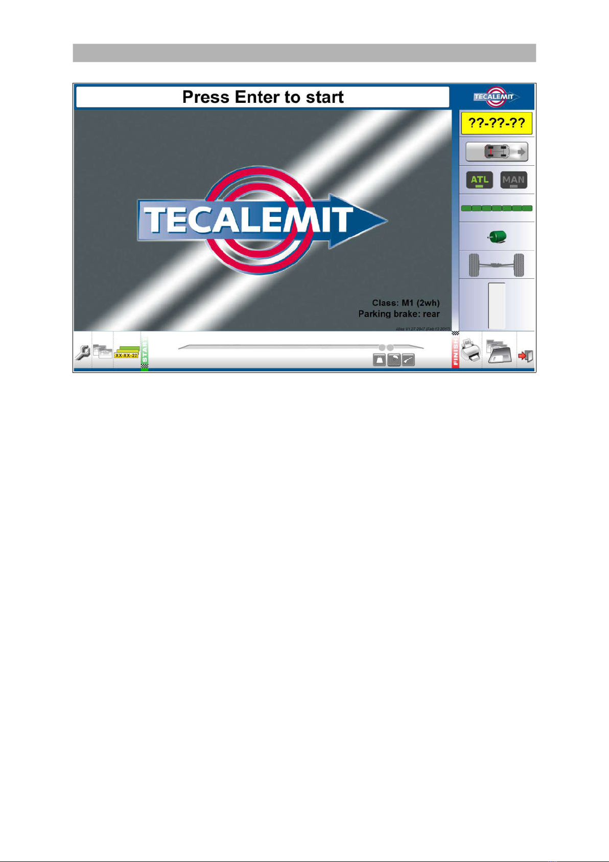
General layout of the start screen
15

General layout of the test lane screens
You can control the test lane program with:
Computer keyboard and mouse.
Remote control.
❶ ❷ ❸ ❹ ❺ ❻ ❼ ❽ ❾
The icons along the bottom show which screen is active.
AREA SCREEN
❶General Settings
❷Customer/Vehicle
❸Select Test Vehicle
❹Drive to start position (start of the tests)
❺
Stage of the test.
Indicates (in green) what axle is tested; the front or rear in combination with one
of the following tests: the service brake, parking brake or weighing.
❻Results Overview
❼Print Results
❽Save Results
❾Exit
You can click on these icons to go directly to a screen.
Use the and buttons on the remote control or keyboard to move between screens.
16
General layout of the test lane screens (continued)
-----A
-----B
-----C
-----D
-----E
-----F
-----G
-----H
The icons and buttons along the right side of the test screens allow you to control and
monitor the tests.
AREA FUNCTION
A Registration number of the vehicle being tested or ??-??-?? in quick test mode.
B Vehicle type: passenger car.
If applicable it shows 4x4.
If applicable it shows the parking brake axle in red.
C Manual button: The system stops at the end of each test, and you must
manually select the next test.
Manual mode is enforced for class 1 & 2, class 3, class 4 (4x4 selectable).
D ATL: All tests automatically.
Automatic mode is disabled for class 1 & 2, class 3, class 4 (4x4 selectable).
E Progress bar: the bar is red/green when a test is in progress and green when
the test is stopped.
F Motor icon: the motor is red when any motor in the test lane is running and
green when all motors are stopped.
The left arrow indicates when the left brake tester motor is running.
The right arrow indicates when the right brake tester motor is running.
G Axle: the number above the axle shows which axle of the vehicle is being tested:
1= front axle, 2 = rear axle, 3 = rear axle (class 7 only). When the floor unit
detects that the wheels are in position, the wheels are shown in green.
H Pause bar: the bar fills up when the system is pausing between tests. In
automatic mode only.
17
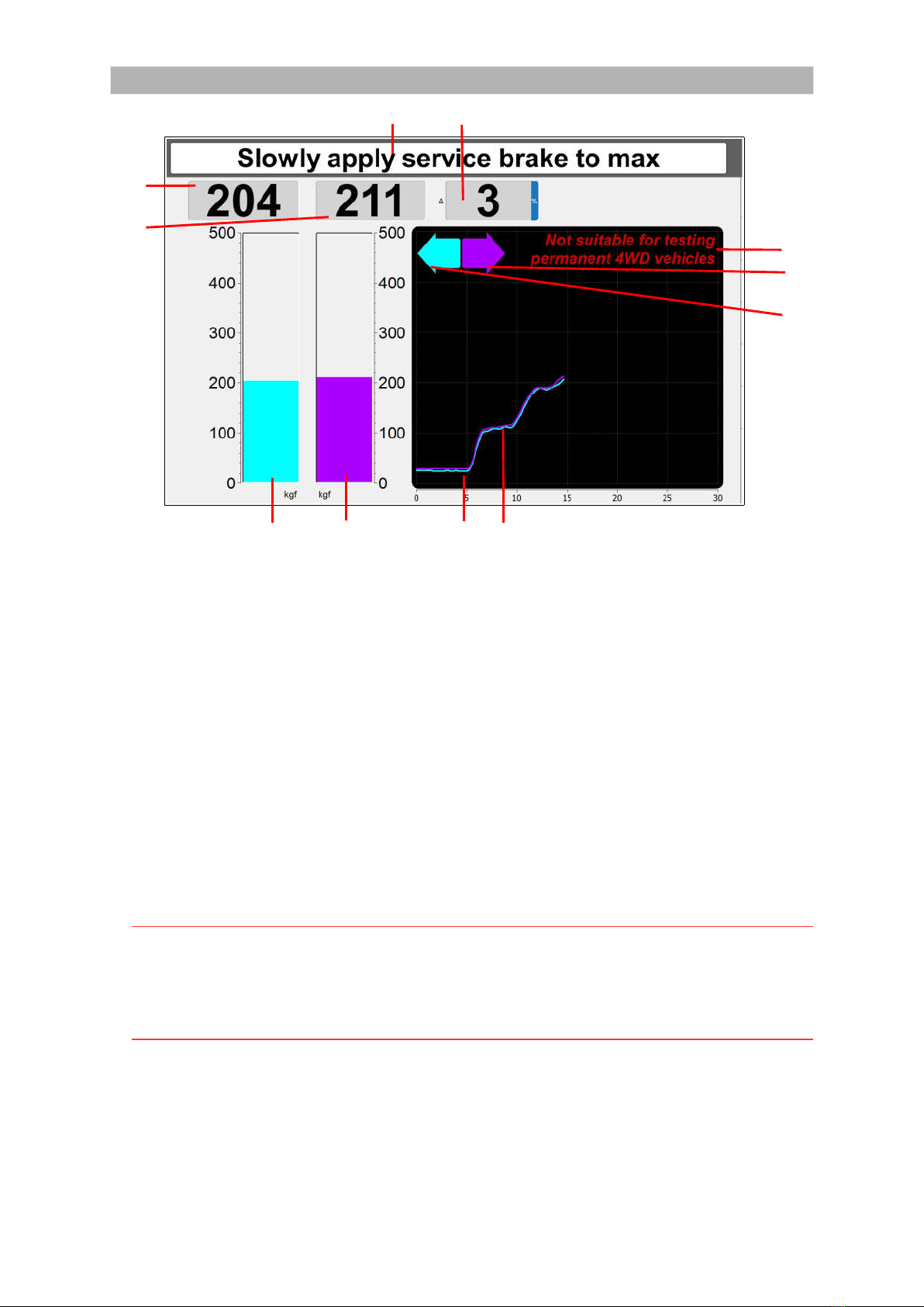
Test screen overview
I J
C
D
K
H
G
A B E F
AREA FUNCTION
A Vertical bar diagram for brake force in KGF for the LEFT wheel of an axle.
B Vertical bar diagram for brake force in KGF for the RIGHT wheel of an axle.
C Brake force in numerical values in KGF for the LEFT wheel of an axle.
D Brake force in numerical values in KGF for the RIGHT wheel of an axle.
E Brake force graph for the LEFT wheel of an axle.
F Brake force graph for the RIGHT wheel of an axle.
G Indicates wheel lock LEFT (slip). When lock occurs, the arrow turns RED.
H Indicates wheel lock RIGHT (slip). When lock occurs, the arrow turns RED.
I Displays the prompts/user instructions.
J Displays the imbalance LEFT/RIGHT in numerical values in % for of an axle.
K Message (fixed): ‘Not suitable for testing permanent 4WD vehicles’.
Note
Brake forces are indicated in kgf.
Weight is indicated in kg.
Imbalance is indicated in %.
Brake efficiencies are indicated in %.
18

Remote control
Navigate using the remote control or keyboard
You can control the test lane program using the remote control (RC) or keyboard (KB).
The following shortcuts are available.
Image shown for illustration
purposes only.
KEY RC FUNCTION KB
General:
F11 Switch full screen mode on or off F11
F2 Switch basic screen mode on or off.
In basic screen mode the icons at the
bottom and the right are hidden. This
allows for more room for the test results.
F2 or F10
9 Increase the character size on test
screens. Disabled during test.
+ (plus key)
or 9
7 Decrease the character size on test
screens. Disabled during test.
– (minus key)
or 7
On the start screen:
1-8 Select vehicle type for quick test mode.
On Start screen only. See chapter Quick
manual test mode Class M1, 4, 5L, 7.
1-8
Increase the character size on the screen. + (plus key)
Decrease the character size on the screen. – (minus key)
and Switch between ATL and MANUAL mode. and
On the test screens:
F3 Go to the start screen Home or F3
F4 Go to Results Overview screen End or F4
Go to the previous test
Go to the next test
OK Start the test if not running
Abort the test if running
Enter
1
2
3
5
8
0
Commands in MANUAL test screens:
1 = start left
2 = start both
3 = start right
5 = start both to centralize
8 = start both to drive out
0 = end of test
1
2
3
5
8
0
On the test queue screen
and Move the selection in the test queue and
OK Test the selected vehicle Enter
Other keys on the RC are not used.
Note
In MOT stations equipped with two or more brake testers, it is necessary that each test
lane is operated by one dedicated remote control only.
Please contact your supplier if two or more remote control sets are required.
19

Chapter 6 Vehicle/customer data
In This Chapter
Add a new vehicle to the database 20
Add a new customer 22
Assign a customer to a vehicle 22
Add a vehicle to the test queue 22
Remove vehicle or customer data 23
Select a vehicle from the test queue 23
Add a new vehicle to the database
❺ ❻ ❼ ❽ ❾ ⓿
❶
❷
❸
❹
❶ + button: Add a new vehicle to the vehicle
list
❷ Vehicle list
❸ Details of the vehicle you selected in the
vehicle list
❹ Required fields
❺ Filter box
❻ X button: remove the filter and show all vehicles
in the list
❼ >> and << buttons: add or remove the selected
vehicle to or from the Test Queue. << Clear:
remove all vehicles from the Test Queue
❽ Test Queue
❾ Details of the customer selected in the
Customer list
⓿ Customer list
The system uses fixed limits to determine if a vehicle passes or fails the tests. The limits are
automatically linked to the selected vehicle. See “General settings Limits Tab” on page 45.
The following information ❹ is mandatory for all vehicle classes:
Registration no. (number plate/license plate)
Make
Model
20
This manual suits for next models
1
Table of contents
Other TECALEMIT Test Equipment manuals


