tecan Balance Kit for SAG 285/01 User manual

Balance Kit, Operating Manual, 393278, en, V1.0
Operating Manual
Balance Kit for SAG 285/01
© 2004, Tecan Schweiz AG, Switzerland, all rights reserved
Information contained in this document is subject to change without notice.
Document Status Sheet
Title: Balance Kit for SAG 285/01, Operating Manual
ID: 393278, en, V1.0
Version Revision Issue Major changes, compatibility
1 0 2004-05-03 First issue

Balance Kit, Operating Manual, 393278, en, V1.0 i
Table of Contents
Table of Contents
1 About This Manual
1.1 Reference Documents . . . . . . . . . . . . . . . . . . . . . . . . . . . . . . . . . . . . . . . . 1-2
1.2 Trademarks . . . . . . . . . . . . . . . . . . . . . . . . . . . . . . . . . . . . . . . . . . . . . . . . 1-2
1.3 Abbreviations . . . . . . . . . . . . . . . . . . . . . . . . . . . . . . . . . . . . . . . . . . . . . . . 1-2
2Safety
2.1 User Qualification. . . . . . . . . . . . . . . . . . . . . . . . . . . . . . . . . . . . . . . . . . . . 2-1
2.2 Notices and Symbols . . . . . . . . . . . . . . . . . . . . . . . . . . . . . . . . . . . . . . . . . 2-2
2.2.1 Warning Notices Used in This Manual. . . . . . . . . . . . . . . . . . . . . . . . . 2-2
2.2.2 Warning Notices Attached to the Product or Its Surroundings. . . . . . . 2-3
2.3 Use of the Product . . . . . . . . . . . . . . . . . . . . . . . . . . . . . . . . . . . . . . . . . . . 2-3
2.4 General Safety Rules . . . . . . . . . . . . . . . . . . . . . . . . . . . . . . . . . . . . . . . . . 2-3
3 Technical Data
3.1 General Description . . . . . . . . . . . . . . . . . . . . . . . . . . . . . . . . . . . . . . . . . . 3-1
3.1.1 Balance Kit. . . . . . . . . . . . . . . . . . . . . . . . . . . . . . . . . . . . . . . . . . . . . . 3-2
3.1.2 SAG 285/01 . . . . . . . . . . . . . . . . . . . . . . . . . . . . . . . . . . . . . . . . . . . . . 3-3
3.2 Technical Data . . . . . . . . . . . . . . . . . . . . . . . . . . . . . . . . . . . . . . . . . . . . . . 3-4
3.2.1 Balance Kit. . . . . . . . . . . . . . . . . . . . . . . . . . . . . . . . . . . . . . . . . . . . . . 3-4
3.2.2 Technical Data of SAG 285/01 . . . . . . . . . . . . . . . . . . . . . . . . . . . . . . 3-5
3.2.3 Supply, Connections . . . . . . . . . . . . . . . . . . . . . . . . . . . . . . . . . . . . . . 3-5
3.3 Requirements. . . . . . . . . . . . . . . . . . . . . . . . . . . . . . . . . . . . . . . . . . . . . . . 3-6
3.3.1 Hardware Requirements . . . . . . . . . . . . . . . . . . . . . . . . . . . . . . . . . . . 3-6
3.3.2 Software. . . . . . . . . . . . . . . . . . . . . . . . . . . . . . . . . . . . . . . . . . . . . . . . 3-7
3.3.3 Access Rights, Passwords. . . . . . . . . . . . . . . . . . . . . . . . . . . . . . . . . . 3-8
3.3.4 Syringes and Liquid for Gravimetric Test. . . . . . . . . . . . . . . . . . . . . . . 3-8
4 Putting into Operation
4.1 Setting up the Balance Kit and the SAG 285/01 . . . . . . . . . . . . . . . . . . . . 4-1
4.1.1 Overview . . . . . . . . . . . . . . . . . . . . . . . . . . . . . . . . . . . . . . . . . . . . . . . 4-1
4.1.2 Unpacking and Inspection . . . . . . . . . . . . . . . . . . . . . . . . . . . . . . . . . . 4-2
4.1.3 For Your Safety . . . . . . . . . . . . . . . . . . . . . . . . . . . . . . . . . . . . . . . . . . 4-2
4.1.4 Preparing the Weighing Cell . . . . . . . . . . . . . . . . . . . . . . . . . . . . . . . . 4-2
4.1.5 Connecting the Weighing Cell to the Control Unit . . . . . . . . . . . . . . . . 4-3
4.1.6 Connecting the SAG 285/01 and the Instrument to the Computer . . . 4-3
4.1.7 Set Communication Protocol and Balance Parameters. . . . . . . . . . . . 4-7
4.1.8 Balance Setup with the Instrument Software . . . . . . . . . . . . . . . . . . . . 4-8
4.1.9 Loading the Worktable Map . . . . . . . . . . . . . . . . . . . . . . . . . . . . . . . . . 4-9
4.1.10 Getting Ready for the Gravimetric Test . . . . . . . . . . . . . . . . . . . . . . . . 4-10
5 Operation
5.1 Operating and Display Elements . . . . . . . . . . . . . . . . . . . . . . . . . . . . . . . . 5-1
5.2 Gravimetric Test. . . . . . . . . . . . . . . . . . . . . . . . . . . . . . . . . . . . . . . . . . . . . 5-2
5.2.1 Safety Instructions . . . . . . . . . . . . . . . . . . . . . . . . . . . . . . . . . . . . . . . . 5-2
5.2.2 Gravimetric Test. . . . . . . . . . . . . . . . . . . . . . . . . . . . . . . . . . . . . . . . . . 5-2

ii Balance Kit , Operating Manual, 393278, en, V1.0
Table of Contents
6 Troubleshooting
6.1 Troubleshooting Table . . . . . . . . . . . . . . . . . . . . . . . . . . . . . . . . . . . . . . . . 6-1
7 Spare Parts and Accessories
7.1 Tecan Spare Parts and Accessories . . . . . . . . . . . . . . . . . . . . . . . . . . . . . 7-2
7.1.1 Balance Kit . . . . . . . . . . . . . . . . . . . . . . . . . . . . . . . . . . . . . . . . . . . . . . 7-2
7.1.2 Uniport . . . . . . . . . . . . . . . . . . . . . . . . . . . . . . . . . . . . . . . . . . . . . . . . . 7-2
7.1.3 Instrument Software . . . . . . . . . . . . . . . . . . . . . . . . . . . . . . . . . . . . . . . 7-3
7.2 Parts from Other Manufactures . . . . . . . . . . . . . . . . . . . . . . . . . . . . . . . . . 7-3
7.2.1 Weighing Module . . . . . . . . . . . . . . . . . . . . . . . . . . . . . . . . . . . . . . . . . 7-3
7.2.2 USB to RS-232 Converters . . . . . . . . . . . . . . . . . . . . . . . . . . . . . . . . . 7-4
8 Customer Support
9 Glossary

1 - About This Manual
Balance Kit V4.7, Operating Manual, 393278, en, V1.0 1 - 1
1 About This Manual
Purpose of This
Chapter
This chapter points out the purpose of the manual, specifies the product the
manual deals with and who the manual is intended for. Furthermore, it explains
the symbols, conventions and abbreviations used and offers other general
information.
Purpose of This
Manual
This manual describes the Balance Kit SAG 285/01and provides all information
required for the proper installation and setup of the kit as a preparatory step for
the Gravimetric Test. In addition, it provides the necessary references to the
document(s) where the Gravimetric Test is described in detail.
Target Group This manual is addressed to advanced users and authorized field service
engineers (FSEs) who wish to run the Gravimetric Test on instruments that are
equipped with a liquid handling arm (LiHa).
Scope This Operating Manual is limited to the following:
Applicable to the installation and setup of the Balance Kit for the Weighing
Module SAG 285/01 from Mettler Toledo AG.
Software for Gravimetric Test: Instrument Software, version 4.2 or later.
Symbols and
Conventions
Cross-references appear as follows: e.g. “Refer to section 1.1.1, 1-1”
– 1.1.1 refers to the corresponding chapter number.
– The symbol denotes the “page number”.
– 1-1 refers to the page number, whereas the first number stands for the
chapter number (chapter 1 - page 1).
Command Sequences for functions of the Instrument Software are printed in
bold type, e.g. Select Liquid System > Balance.
Note: The symbols pertaining to safety (WARNINGS and ATTENTIONS) are
explained in Chapter 2 “Safety”,
2-1.
For Your Safety Before performing any work on or with the Balance Kit, first read the
Operating Manual carefully, in particular chapter 2 “Safety”.

1 - 2 Balance Kit V4.7, Operating Manual, 393278, en, V1.0
1 - About This Manual
Reference Documents
1.1 Reference Documents
This section provides a list of documents which are needed or may be useful in
connection with the Balance Kit.
System
Manuals
Operating Manuals of instrument on which Balance Kit is to be installed.
Service Manual of instrument on which Balance Kit is to be installed.
Operating Manual of balance (provided by the manufacturer)
Operating Manual for Balance Kit for Mettler SAG 285/01 (Doc ID 393278)
Instrument
Software
Manuals
Software Version V4.2 (Genesis Classic, Doc ID 390 791)
Software Version V4.3 (Genesis Freedom, Doc ID 392 179)
Software Version V4.5 (Freedom EVO, Genesis Freedom & Classic,
Doc ID 390 791)
Software Version V4.6 and later (Freedom EVO, EVOlyzer, Genesis Freedom
& Classic, Doc ID 392 888)
1.2 Trademarks
The following product names and any registered and unregistered trademarks
mentioned in this manual are used for identification purposes only and remain the
exclusive property of their respective owners:
WindowsTM is a registered trademark of Microsoft Corporation
SAG 285/01, AG 285 and AG 245 are trademarks of Mettler Toledo AG.
UC-232A is a trademark of Aten International Company Ltd.
EX-1331 and EX1334 are trademarks of Exsys Vertriebs GmbH.
1.3 Abbreviations
CAN Controller Area Network
FSE Field Service Engineer
LiHa Liquid Handling Arm
RoMa Robotic Manipulator Arm
USB Universal Serial Bus

2 - Safety
User Qualification
Balance Kit V4.7, Operating Manual, 393278, en, V1.0 2 - 1
2 Safety
Purpose of This
Chapter
This chapter specifies the intended use of the Balance Kit and points out the
safety concept. It contains general rules of behavior and warnings from hazards
pertaining to the use of the kit.
Significance of
These Safety
Instructions
Please note that the Balance Kit itself does not contain any hazardous parts.
However, it is installed on instruments where it is necessary to perform the
Gravimetric Test. Such instruments are equipped with parts that can move with
great force and at considerable speed. Moreover, these instruments often handle
toxic or other chemically and biologically hazardous substances which require
adequate safety measures.
As a consequence, the safety of users and personnel can only be ensured if the
safety instructions in this manual and the relevant hardware and software
manuals of the instruments on which the Gravimetric Test is run, are strictly
observed and followed.
Therefore, the relevant manuals must always be available to all persons
performing the tasks described herein.
2.1 User Qualification
What Users
Must Know
All users (laboratory personnel, Tecan authorized field service engineers (FSEs)
etc.), must be qualified and trained to install and use the Balance Kit for the
Gravimetric Test.
In particular, users must fulfill the following qualifications:
They must have a thorough knowledge of the application run on the system.
They must be familiar with the good laboratory practice guidelines.
The must be familiar with the relevant setup and test procedures described in
the “Instrument Software Manual”.
They must know how to set up and operate the Balance that is to be used
together with this kit.
They must have read and understood the instructions in this Operating
Manual.
Only persons who meet the qualifications prescribed here are authorized to
perform the work described in this Operating Manual.
Training
Courses
Note: Tecan recommends that users attend an appropriate training course.
• Please ask your nearest Tecan representative about the available courses.
2 - 2 Balance Kit V4.7, Operating Manual, 393278, en, V1.0
2 - Safety
Notices and Symbols
2.2 Notices and Symbols
2.2.1 Warning Notices Used in This Manual
The symbols used for safety-related notices have the following significance:
WARNING
Symbols
WARNINGS appear as follows:
WARNING
Generally, the triangular warning symbol indicates the possibility of personal injury
or even loss of life if the instructions are not followed.
Whenever possible, the symbol indicates the hazard a person is exposed to more
specifically. The symbols used in this Operating Manual have the following
significance:
WARNING
Toxic substances
WARNING
Biological hazard
WARNING
Radioactive radiation
WARNING
Pinch point, mechanical hazards

2 - Safety
Use of the Product
Balance Kit V4.7, Operating Manual, 393278, en, V1.0 2 - 3
ATTENTION
Symbols
ATTENTIONS appear as follows:
ATTENTION
With the general “Read This!” symbol, ATTENTIONs indicate the possibility of
equipment damage, malfunctions or incorrect process results, if instructions are
not followed.
2.2.2 Warning Notices Attached to the Product or Its Surroundings
There are no warning notices attached to the Balance Kit.
2.3 Use of the Product
Intended Use The Balance Kit described in this manual is to be used exclusively together with
the Mettler-Toledo balance model SAG 285/01.
Improper Use The Balance Kit described in this manual is not suitable for other balance models
(e.g. Mettler AG 285 or AG 245).
2.4 General Safety Rules
Legal
Regulations
Legal regulations, such as local, state and federal laws which prescribe the use or
application as well as the handling of dangerous materials in connection with the
Balance Kit must be strictly followed.
Duty of
Maintenance
and Care
The user is responsible for ensuring that the Balance Kit and the balance itself are
used in proper condition only. Maintenance, service, and repair jobs on the
instrument on which the Balance Kit is to be used must be performed with care
and on schedule, and by authorized personnel only.
Observe
Specific Safety
Instructions
When setting up and using the Balance Kit pay due attention to the safety
instructions as laid out in the following manuals:
Operating Manual of the specific instrument
Service Manual of the specific instrument
Instrument Software Manual
Operating Manual of the balance

2 - 4 Balance Kit V4.7, Operating Manual, 393278, en, V1.0
2 - Safety
General Safety Rules
3 - Technical Data
General Description
Balance Kit Operating Manual, 393278, en, V1.0 3 - 1
3 Technical Data
Purpose of This
Chapter
This chapter introduces the reader to the Balance Kit and its main components. It
contains technical data, requirements and performance data.
3.1 General Description
What Is a
Balance Kit?
The Balance Kit is a set of components that are needed to adapt the Mettler
Toledo Weighing Module SAG 285/01 to the instrument so that it can be used for
the Gravimetric Test.
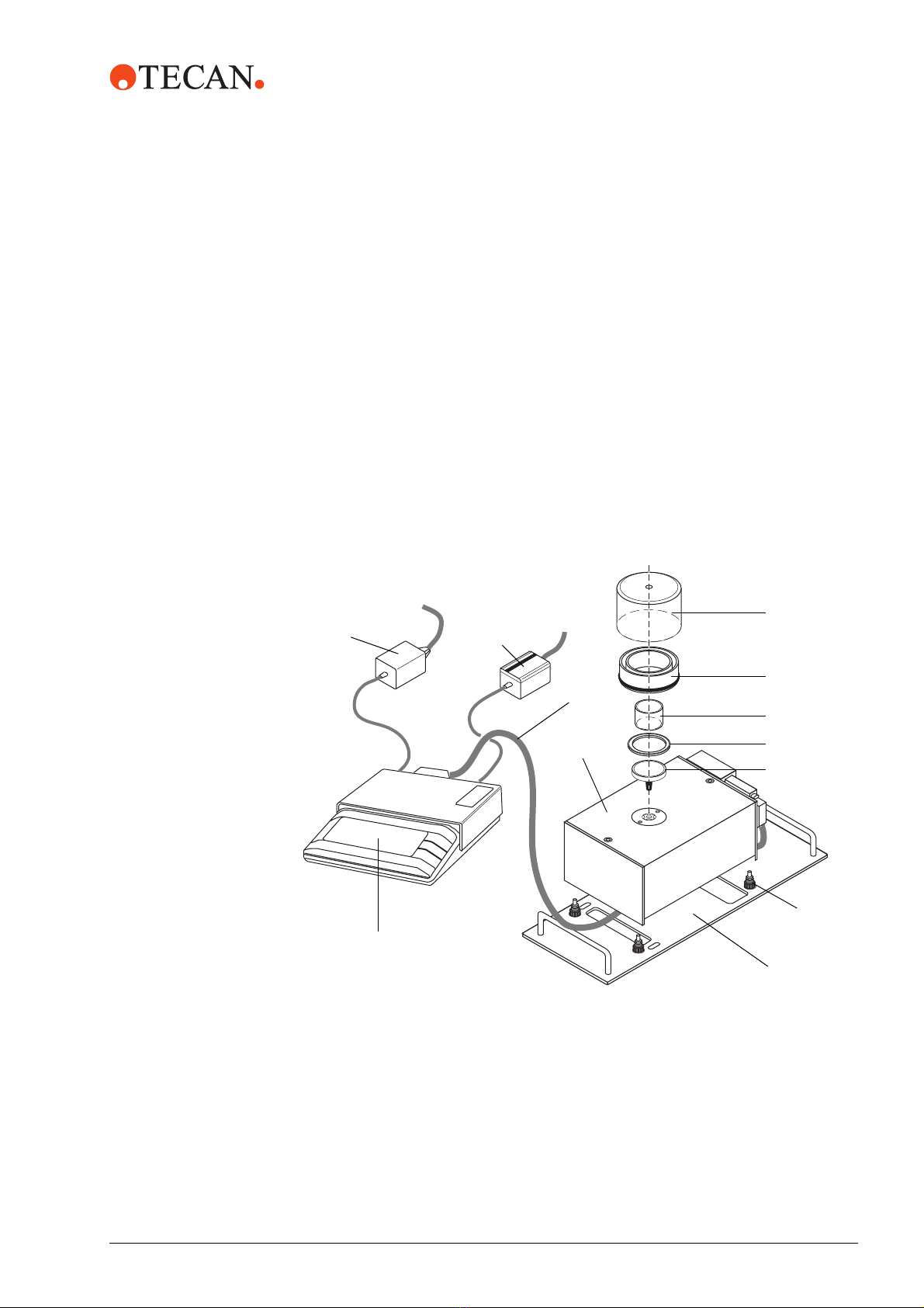
Overview The following figure provides a quick overview of both the Balance Kit and the
SAG 285/01 from Mettler Toledo. Brief descriptions are given in the sections after
the figure.
Fig. 3-1 Parts of Balance Kit + SAG285/01 (Weighing Cell and Control Unit)
A
B
C
D
E
F
G
H
I
J
LK
A
Draft shield
BRing for evaporation compensation
CVessel
DCentering ring
EWeighing pan (Mettler)
FFoot with counternut
GAdapter plate
HWeighing cell (Mettler)
IConnection cable (Mettler)
JControl unit (Mettler)
KConnection cable LC-RS9 (Mettler)
LPower supply (Mettler)

3 - 2 Balance Kit Operating Manual, 393278, en, V1.0
3 - Technical Data
General Description
3.1.1 Balance Kit
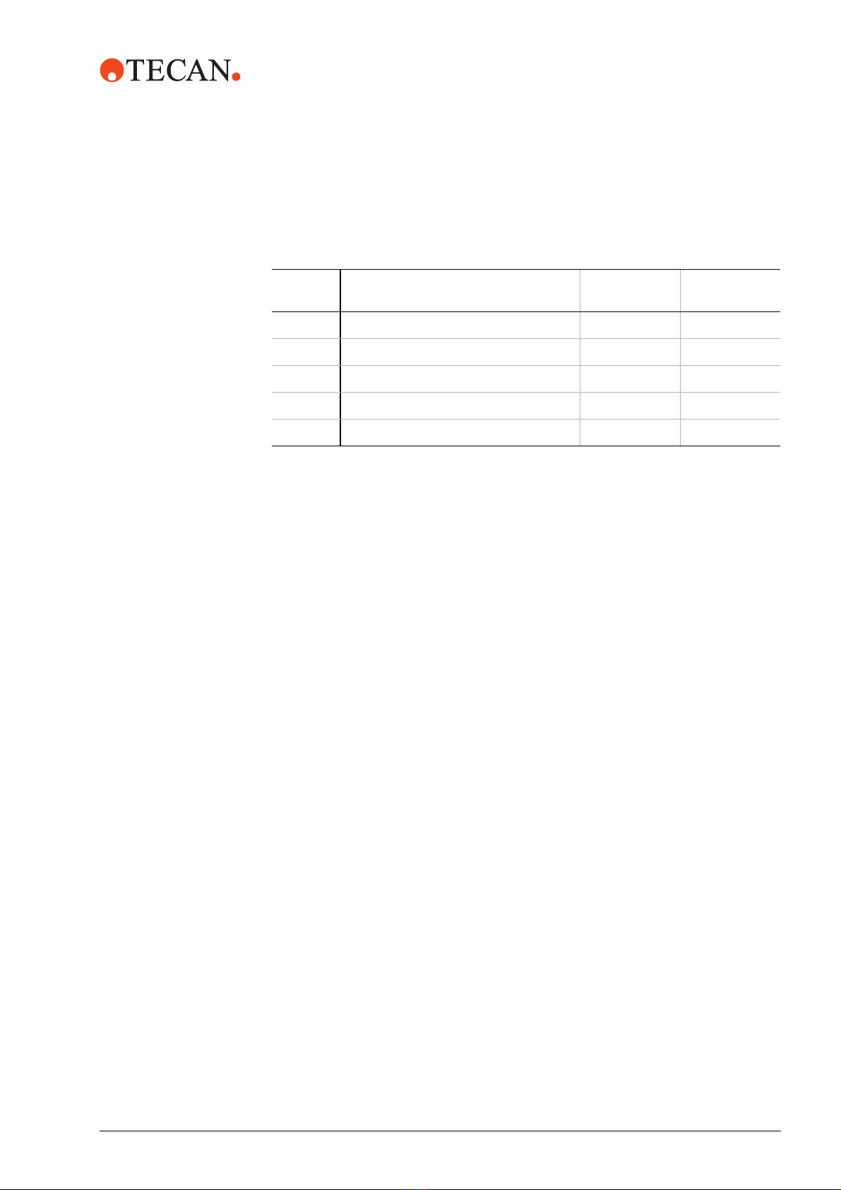
The following table lists the parts the Balance Kit consists of. Also refer to
Fig. 3-1, 3-1.
Ordering the
Balance Kit
The Balance Kit (or certain parts of it) can be ordered from Tecan or via a local
Tecan representative. For more details see section
7 “Spare Parts and Accessories”, 7-1.
Note: The Balance Kit does not comprise the Weighing Module (weighing cell +
control unit), nor are the connection cable and other accessories part of the kit.
These items must be ordered directly from Mettler Toledo AG (see next section).
Tab. 3-1 Parts of the Balance Kit
Item in
Figure
Quantitiy Designation Explanation
A1 Draft shield Protects the vessel (C) with the liquid to be weighed
from air drafts.
B1 Evaporation
ring
This ring is placed on the Weighing Cell (H) as shown
in the figure. It contains a groove that can be filled with
distilled or de-ionized water. During operation, part of
this liquid evaporates and thus increases the air
humidity under the draft shield. This, in turn, has the
effect that less liquid evaporates from the vessel dur-
ing the Gravimetric Test. In this way, the accuracy of
the test results is increased indirectly.
C2 Vessel Contains the liquid to be weighed during the Gravimet-
ric Test. The vessel rests on the weighing pan (E).
D1 Centering ring Holds the evaporation ring (B) in place
F1 Adapter plate Plate with two handles and positioning slots that can
be placed in the appropriate grid position on the work-
table. It also has four positioning holes that allow posi-
tioning the Weighing Cell (H) properly on the plate.
G4 Foot + counter-
nut
The four feet are standard knurled screws with a plas-
tic head. They are screwed to the bottom of the Weigh-
ing Cell (H) and can be used to level out the Weighing
Cell. The counternuts serves for securing the feet.

3 - Technical Data
General Description
Balance Kit Operating Manual, 393278, en, V1.0 3 - 3
3.1.2 SAG 285/01
Brief
Description
The SAG 285/01 is a product of Mettler Toledo AG and has been available since
January 2004. This SAG 285/01 consists of a Weighing Cell (H) and a separate
Control Unit (J) that are interconnected with a cable. Thanks to this separation a
higher precision and stability can be attained.
The SAG 285/01 is a substitute for the predecessor model AG 285 which
incorporated the weighing cell, the display and the operating and control elements
in one unit. Note, that this model is no longer available.
The following two tables list the parts that must be ordered directly from Mettler
Toledo:
Tab. 3-2, 3-3 lists the parts the SAG 285/01consists of.
Tab. 3-3, 3-3 lists the accessories that must be ordered separately.
See also Fig. 3-1 , 3-1.
Ordering the
SAG 285/01 and
Accessories
See section 7 “Spare Parts and Accessories”, 7-1.
Tab. 3-2 Weighing Module SAG 285/01
Item in
figure
Quantity Designation Explanation
H1 Weighing Cell Is placed on the adapter plate (F) and actually weighs
the liquid in the vessel.
J1 Control Unit The control unit is separated from the weighing cell
(H). It contains a digital display and the necessary con-
trols that allow operating the whole Weighing Module.
I1 Connection
cable 1.5 m
Connects the Weighing Cell to the Control Unit. Please
note that a 5 m cable is available as an option (see
below)
L1 Power supply This power supply unit is connected to the control unit.
Tab. 3-3 Accessories for the SAG 285/01
Item in
Figure
Quantity Designation Explanation
E1 Weighing pan,
∅50 mm
Carries the vessel with the liquid to be weighed.
K1 Cable LC-RS9 Cable with local CAN bus to RS-232 adapter that con-
nects the Control Unit to the computer.
I1 Connection
cable 5 m
Optional. Can be used instead of the 1.5 m cable to
connect the Weighing Cell to the Control Unit.
-- 1 Transport case Optional accessory that allows transporting the
SAG 285/01.

3 - 4 Balance Kit Operating Manual, 393278, en, V1.0
3 - Technical Data
Technical Data
3.2 Technical Data
3.2.1 Balance Kit
Overall
Dimensions
The following figure shows the overall dimensions of the adapter plate with
installed Weighing Cell and draft shield.
Fig. 3-2 Adapter plate with weighing cell and draft shield
Tab. 3-4 Adapter plate (with / without weighing cell and draft shield)
Dimension Measurement [mm / in.]
Overall height with installed Weighing Cell
with draft shield
htapprox.
130 / 5.1a)
a) Exact value depends on the adjustment of the feet
Height of adapter plate (with handles, without
Weighing Cell)
ha2 38 / 1.5
Thickness of adapter plate ha1 6 / 0.23
Length of adapter plate la339.5 / 13.4
Width of adapter plate wa149 / 5.9
Grid positions occupied by adapter plate on
worktable
wa6 grids
la
ha2
ha1
ht
wa
3 - Technical Data
Technical Data
Balance Kit Operating Manual, 393278, en, V1.0 3 - 5
Other Parts
of Kit
The following table shows the heights and diameters of the other parts of the
Balance Kit. Also see Fig. 3-1 , 3-1.
Weight The Balance Kit (parts A, B, 2 x C, D, F and G) without packaging weighs approx.
1.1 kg (2.42 lb.).
3.2.2 Technical Data of SAG 285/01
For details refer to the SAG 285/01 Operating Manual from Mettler Toledo AG.
3.2.3 Supply, Connections
Balance Kit The Balance Kit contains only mechanical parts; there are no electrical
connections.
SAG285/01 The SAG 285/01 is supplied and connected as follows:
Power supply: Via a separate power supply (included in delivery) that is
connected to the Control Unit.
Interconnection between Control Unit and Weighing Cell: Connection cable
1.5 m (included in delivery) or optional 5 m cable.
Connection to computer: From Control Unit via separate LC-RS9 cable (to be
ordered separately).
Tab. 3-5 Dimensions of Parts of Kit
Item in
figure
Designation Height
[mm / in.]
Diameter
[mm / in.]
A Draft shield 55 / 2.2 95 / 3.7
B Evaporation ring 25 / 0.98 87 / 2.2
C Vessel 25 / 0.98 41 / 1.6
D Centering ring 3 / 0.12 62 / 2.4
F Foot 23 / 0.91 16 / 0.63

3 - 6 Balance Kit Operating Manual, 393278, en, V1.0
3 - Technical Data
Requirements
3.3 Requirements
3.3.1 Hardware Requirements
Instrument and Computer
Instrument The Balance Kit together with the SAG 285/01can be used on the following
instruments types: Freedom EVO instruments, Genesis Freedom and Genesis
Classic instruments.
Computer Hardware requirements as specified in the Instrument Software Manual that
corresponds to the installed version of the Instrument Software.
Possible interfaces for connecting the instrument and the SAG 285/01 see below.
Interfaces, Adapters
There is more than one possibility to connect the instrument and the SAG 285/01
to the computer.
Two RS-232
Ports
If the computer has two free RS-232 ports, both the SAG 285/01 and the
instrument can be connected directly.
Note: Depending on the connectors at the instrument cable and the computer,
adequate 9 to 25-pole RS-232 adapters and / or gender changers may be
needed.
USB Ports To connect the instrument and/or the SAG 285/01 to the computer via USB ports,
an appropriate USB to Serial converter is needed.
Recommended USB to Serial converters:
Aten UC-232A USB to RS232 Converter. Has one RS-232 connector and
plugs into a USB port on the computer.
Exsys EX-1331 USB to RS232 Converter. One RS-232 and 1 one USB
connector.
Exsys EX-1334 USB to RS-323 Converter. Has four RS-232 connectors and
plugs into a single USB port on the computer.
The above converters feature the following:
Data rate: Up to 230 Kb per second
RS-232 connectors: Male DB9
Compliant with USB Specifications V1.1
Suitable for Windows 2000 and XP
Note: A mixed connection (instrument to RS-232, SAG 285/01 via USB) is also
possible.

3 - Technical Data
Requirements
Balance Kit Operating Manual, 393278, en, V1.0 3 - 7
Connection via
Uniport
If the computer has only one free RS-232 port and no USB port, the SAG 285/01
may be connected via the Uniport board, provided the following conditions are
fulfilled:
Instrument Software V4.5 or earlier is installed on the computer.
The instrument is equipped with a Uniport board.
Note:
• Apart from Genesis RMP or instruments used in customized solutions, Tecan
instruments are not normally equipped with a Uniport board.
• If possible, a separate Uniport board may be installed for the Gravimetric
Test.
• The connection via the Uniport is not supported by the Instrument Software
version V4.6 or later.
3.3.2 Software
Instrument
Software
Version V4.2 or later is required.
Note: The connection of the SAG 285/01 via Uniport is no longer supported from
Instrument Software Version 4.6 or later.
Operating
System
According to specifications of installed version of Instrument Software.
Drivers for
USB / RS-232
Converters
The delivery of the recommended USB to RS-232 converters includes drivers that
are suitable for Windows 2000 and Windows XP.

3 - 8 Balance Kit Operating Manual, 393278, en, V1.0
3 - Technical Data
Requirements
3.3.3 Access Rights, Passwords
To carry out the Balance Setup function and the Gravimetric Test with the
Instrument Software you need the following access rights:
Version V4.6x or earlier: No password required.
Version V4.7 or later: From version V4.7 onwards, all users need a user
account, together with a user name and a password.
– There are several predefined user groups with different authorization
levels.
– The Balance Setup and the Gravimetric Test can be carried out by users
with SnS_Customer access rights.
Note: For detailed information about user accounts, passwords and access rights
refer to the Instrument Software Manual (for software version V4.7 or later),
section “Tecan User Administration System”.
3.3.4 Syringes and Liquid for Gravimetric Test
Syringes: 250 µl, 500 µl, 1 ml.
System liquid: Demineralized or de-ionized and degassed water. Water
temperature should correspond to ambient temperature.
Pipetting liquid: Tap water. Water temperature should correspond to ambient
temperature.

4 - Putting into Operation
Setting up the Balance Kit and the SAG 285/01
Balance Kit Operating Manual, 393278, en, V1.0 4 - 1
4 Putting into Operation
Purpose of This
Chapter
This chapter describes how the Balance Kit is installed and gives instructions on
initial operation.
4.1 Setting up the Balance Kit and the SAG 285/01
4.1.1 Overview
The following figure provides an overview of the Balance Kit and the SAG 285/01
Weighing Module. For a description and the detailed specifications see section
3.1, 3-1.
Fig. 4-1 Parts of Balance Kit + SAG285/01 (Weighing Cell and Control Unit)
A
B
C
D
E
F
G
H
I
J
LK
A
Draft shield
BRing for evaporation compensation
CVessel
DCentering ring
EWeighing pan (Mettler)
FFoot with counternut
GAdapter plate
HWeighing cell (Mettler)
IConnection cable (Mettler)
JControl unit (Mettler)
KConnection cable LC-RS9 (Mettler)
LPower supply (Mettler)

4 - 2 Balance Kit Operating Manual, 393278, en, V1.0
4 - Putting into Operation
Setting up the Balance Kit and the SAG 285/01
4.1.2 Unpacking and Inspection
1Unpack the Balance Kit and the SAG 285/01.
2Ensure that no parts are missing or damaged.
3Check whether the voltage range of the SAG 285/01 supply unit corresponds
with the local mains voltage.
4Contact the supplier of the SAG/01 or your nearest Tecan representative if
any parts are missing or damaged.
4.1.3 For Your Safety
WARNING
Damage to the system and danger of electric shock.
Always switch the instrument and the computer off before making any electric
connections or opening the instrument’s access door.
4.1.4 Preparing the Weighing Cell
Also see Fig. 4-1 , 4-1.
4Carefully place the Weighing Cell onto the adapter plate with the feet inserted
into the corresponding positioning holes.
5Check whether the Weighing Cell is seated properly on the adapter plate and
does not wobble. If necessary adjust the cell by turning the feet until the cell is
level and stable.
6Carefully tighten the counternuts to secure the feet when done.
7Place the centering ring (D) on the cell and insert the cone of the weighing pan
(E) into the corresponding hole as shown in the figure.
To prepare the Weighing Cell:
1Screw the counternuts on the
screw bolts of the feet (F)
down until the stop.
2Screw the feet (F) into the
corresponding mounting
holes at the bottom of the
Weighing Cell (H).
3Place the adapter plate (G)
on a the worktable in the grid
position where you want to
perform the Gravimentric test
later.
D
E
F
G
H
Table of contents
Other tecan Accessories manuals


