Tecfluid FLOMAT Series User manual

R-MI-FAXL1 Rev.: 0 english version
Series FLOMAT
Sensor FLOMAT-XL + Converter XL1
Instructions manual
The art of measuring

2
Thank you for choosing a product from Tecfluid S.A.
This instruction manual allows the installation, configuration,
programming and maintenance. It is recommended to read it before
using the equipment.
This document shall not be copied or disclosed in whole or in any
part by any means, without the written permission of Tecfluid S.A.
Tecfluid S.A. reserve the right to make changes as deemed
necessary at any time and without notice, in order to improve the
quality and safety, with no obligation to update this manual.
Make sure this manual goes to the end user.
Keep this manual in a place where you can find it when you need
it.
In case of loss, ask for a new manual or download it directly from
our website www.tecfluid.com Downloads section.
Any deviation from the procedures described in this instruction
manual, may cause user safety risks, damage of the unit or cause
errors in the equipment performance.
Do not modify the equipment without permission. Tecfluid S.A. are
not responsible for any problems caused by a change not
allowed. If you need to modify the equipment for any reason,
please contact us in advance.
PREFACE
WARNINGS

3
TABLE OF CONTENTS
SERIES FLOMAT
1 INTRODUCTION ........................................................................... 5
2 RECEPTION ................................................................................. 6
2.1 Unpacking .......................................................................... 6
2.2 Storage temperatures ......................................................... 6
3 HANDLING ................................................................................... 6
4 INSTALLATION ............................................................................. 6
4.1 Straight pipe sections ......................................................... 6
4.1.1 Mixtures ................................................................ 8
4.2 Sensor position .................................................................. 8
4.3 Valves ............................................................................... 8
4.4 Pumps ................................................................................ 9
4.5 Aeration ............................................................................. 9
4.6 Vibrations ........................................................................... 10
4.7 Magnetic fields .................................................................. 10
4.8 Temperature ...................................................................... 10
5 MOUNTING .................................................................................. 11
5.1 Pipe adaptor mounting ....................................................... 11
5.2 Sensor mounting ................................................................ 13
5.3 Tightening torque ................................................................ 13
5.4 Electronic converter connection .......................................... 13
5.5 Electronic converter programming ........................................ 13
6 ELECTRICAL CONNECTION ........................................................... 14
6.1 Power supply wiring ............................................................ 14
6.2 Analog output wiring ........................................................... 15
6.3 Digital output wiring ............................................................ 16
7 ASSOCIATED SOFTWARE WINSMETER XL1 ................................. 18
7.1 USB cable connection and software installation ................... 18
7.2 Port connection ................................................................... 19

4
7.3 Password ........................................................................... 20
7.4 Access to “Installation” ....................................................... 24
7.4.1 Sensor .................................................................. 24
7.4.2 Power supply ......................................................... 24
7.5 Access to “Programming” ................................................... 25
7.5.1 Current loop .......................................................... 25
7.5.2 Units ....................................................................... 26
7.5.3 Digital output ......................................................... 26
7.5.4 Current loop calibration .......................................... 26
7.6 Visualization ....................................................................... 27
7.7 Zero flow drift adjustment .................................................... 27
7.8 Datalogger ......................................................................... 28
7.9 Firmware updates ............................................................... 29
7.10 Configuration file ................................................................. 30
8 MAINTENANCE ............................................................................ 31
9 TECHNICAL CHARACTERISTICS ................................................... 32
10 SAFETY INSTRUCTIONS ............................................................... 33
10.1 Pressure equipment directive .............................................. 33
10.2 Certificate of conformity TR CU (EAC marking) ..................... 33
11 DIMENSIONS ............................................................................... 34
12 TROUBLESHOOTING .................................................................... 37
ANNEX Flow rate diagram ................................................................... 38

5
1INTRODUCTION
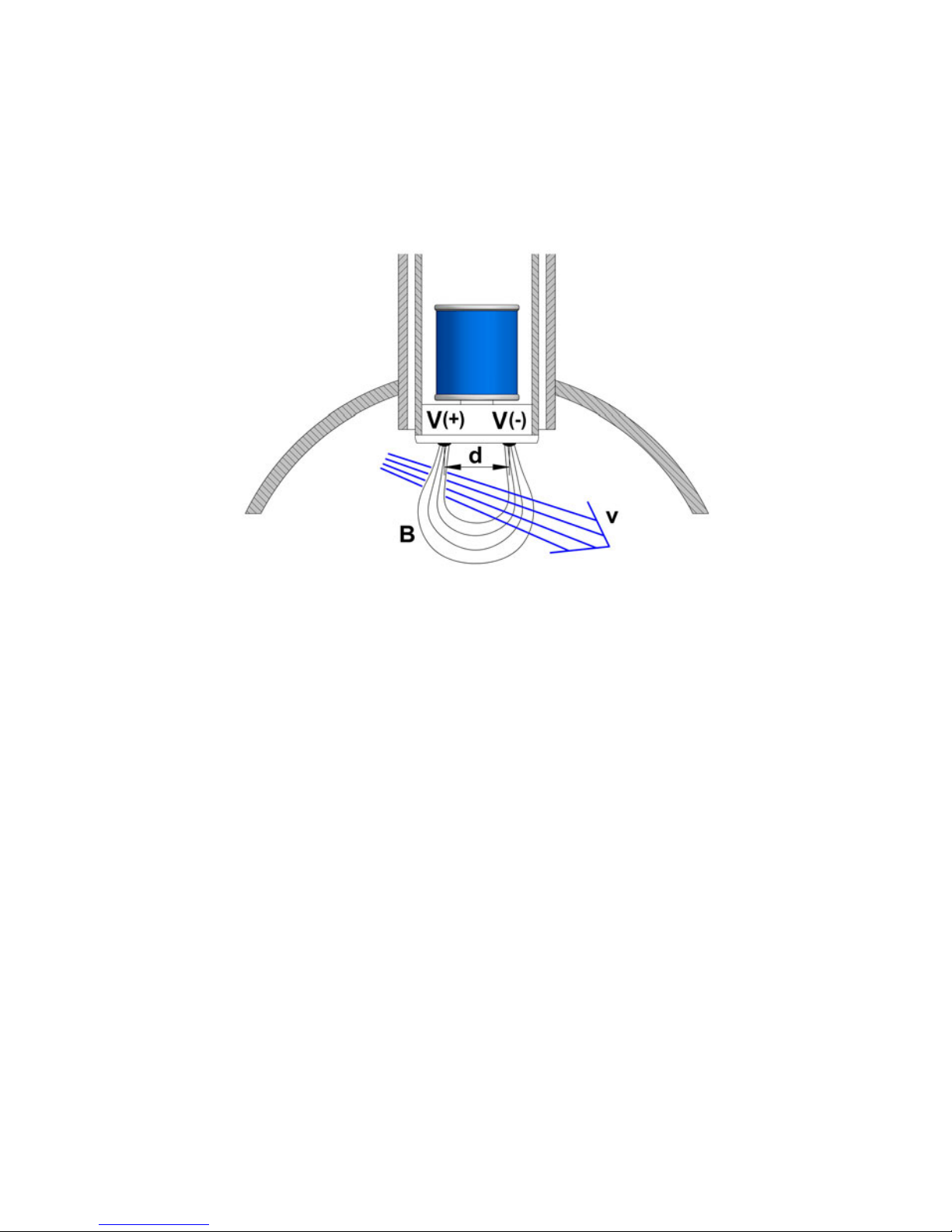
The FLOMAT electromagnetic flowmeters are based on Faraday’s induction law.
When an electrically conductive liquid flows through a magnetic field, perpendicular to the
flow direction, it induces a voltage V proportional to the liquid velocity.
Two electrodes in contact with the liquid and positioned perpendicularly to the magnetic
field, sense this voltage V.
The electronic converter is based on the most advanced technology in digital signal
processing, in order to obtain accurate and reliable measurements.
The device provides the following features:
Coil excitation by means of pulsed signal to obtain a negligible zero offset.
Pulse and current output proportional to the flow rate and user programmable.
V = B·v·d
Where:
V = Measured voltage in the electrodes
B = Magnetic field
v = Liquid velocity
d = Distance between electrodes

6
4.1 Straight pipe sections
The point where the FLOMAT sensor will be installed must be a straight pipe section,
separated from elements that can disturb the flow profile, such as elbows, diameter
changes, etc. Depending on the element the minimum necessary distances upstream from
the sensor are shown on the next page (BS 1042-2.2:1983 standard):
2 RECEPTION
The FLOMAT electromagnetic flowmeters with XL1 converter are supplied conveniently
packaged for transportation together with their instruction manual for installation and
operation.
All the flowmeters have been verified in our calibration rigs to obtain the gain factor for each
sensor.
2.1 Unpacking
Unpack the instrument carefully, removing any remains of the packing.
2.2 Storage temperatures
-20ºC ...... +60ºC
3 HANDLING
It should always be done with care and without knocks.
4 INSTALLATION
This should be made in a straight pipe run that guarantees that the pipe is always completely
full.
Avoid high points of the pipes where air pockets usually form, or pipes with downwards
flow where vacuums can occur.
Partially full pipes can involve important reading errors.
Flow rate measurement with open discharge makes it necessary to install the flowmeter in a
pipe section with a siphon which avoids stagnation of air in the sensor.

7
Disturbing element
upstream the
sensor
Minimum distance between
the sensor and the element
Several 90º
coplanar bends
Fully opened plug
valve
Fully opened
butterfly valve
90º elbow
Several 90º non-
coplanar bends
T accessory
Total angle
convergent 18 to 36°
Total angle
divergent 14 to 28°

8
4.2 Sensor position
The optimum position to install the sensor is with the electrodes in the side of the pipe. This
way, air pockets at the top of the pipe are avoided.
Downstream, the minimum recommended distance to a disturbing element is 5 x DN.
4.1.1 Mixtures
If liquids of different conductivities are mixed it is necessary to install the sensor a minimum
of 50 x DN from the point of mixture in order to obtain a uniform conductivity of the liquid
and stabilize the readings.
If this distance is shorter, readings may be unstable.
4.3 Valves
Control valves or shut-off valves should always be installed downstream from the sensor to
assure that the pipe is always full of liquid.

9
4.5 Aeration
If there is a point where the difference in level is higher than 5 m an air inlet valve should be
installed after the sensor to avoid a vacuum effect that could damage the sensor.
4.4 Pumps
Pumps should be mounted upstream from the sensor to avoid the suction of the pump
(vacuum).

10
4.6 Vibrations
Vibrations of the pipes should be avoided by anchoring the pipe before and after the sensor.
The vibration level should be less than 2.2 g in the range of 20 -150 Hz according to IEC 068
-2-34.
4.8 Temperature
In open air installations it is recommended to install a protection to avoid direct sun light on
the flowmeter.
4.7 Magnetic fields
Strong magnetic fields close to the sensor should be avoided.

11
With thermally insulated pipes DO NOT insulate the sensor. High temperatures can damage
it.
The maximum liquid temperatures are shown on page 32.
5 MOUNTING
5.1 Pipe adaptor mounting
The sensor is normally supplied mounted in its pipe adaptor. Before welding the adaptor to
the pipe, the sensor must be removed to avoid irreparable damage due to excessive
temperatures.
There are two basic types of pipe adaptors: with threaded or with flanged connection.
For the smallest pipe diameters (DN40, 50 & 65) the pipe adaptor is supplied welded to a
short length of pipe with a “T” form. For this type just couple it to the pipe by welding or
gluing in the case of PVC, PP, PE or other plastics.

12
For DN80 and bigger, there are three lengths for each of the two types of fittings.
The process of putting the pipe adaptor in should be done accurately. The distance (H) (see
drawings on next page) which is what the pipe adaptor should protrude above the surface of
the pipe is important.
As shown in the table on the next page, to know the distance, the thickness of the pipe s
must be known.
In order to make the positioning of the pipe adaptor in the pipe easier, there is a label on one
of its sides with markings indicating the position of the internal pipe diameter for each DN.
Cut this label above the line corresponding to the DN of the pipe, at a distance equal to the
pipe thickness. Peel off the bottom part of the label. Once the pipe adaptor is placed into its
final position, where the label was cut must coincide with the outer diameter of the pipe.
This ensures that the measuring electrodes penetrate far enough in the area of flow profile
that will allow an accurate measurement.
DN C (mm) Insert pipe adaptor
L (mm) H (mm)
80 10
93
88-s
100 12,5 85,5-s
125 15,5 82,5-s
150 19 79-s
200 25 73-s
250 31 67-s
300 37,5 60,5-s
350 44 54-s
400 50 48-s
500 62,5
145
140,5-s
600 75 128-s
700 87,5 115,5-s
800 100 103-s
900 112,5 90,5-s
1000 125 78-s
1200 150 203-s
1400 175 178-s
1600 200 153-s
1800 225 128-s
2000 250 103-s
205

13
Example:
Suppose a pipe of 300 mm inner diameter (DN300) and 5.5 mm thick. In the chart we can
see that the distance that the pipe adaptor must extend above the external wall is H = 60.5 -
s = 60.5 - 5.5 = 55 mm.
The values in the chart are calculated considering the gasket supplied with the instrument,
which is 3 mm thick. If the thickness of the gasket is changed, the value of H will change.
The equation to calculate H’ for a gasket of thickness d is the following:
H’ = H + 3 - d
In the previous example, if the gasket was 5 mm thick, the distance that the adaptor should
extend above the external wall would be H’ = 55 + 3 - 5 = 53 mm.
Drill a 48.5 mm diameter hole in the pipe to insert the pipe adaptor and weld the fitting to the
pipe.
If the pipe is made of concrete or other material to which the pipe adaptor cannot be
welded, a clamp-on accessory or saddle should be used. In this case, please contact us to
inform about the suitable sensor length.
The axis of the pipe adaptor should be perfectly perpendicular to the pipe axis.
5.2 Sensor mounting
Once the pipe adaptor is mounted, place the flat seal in its position and install the sensor
with the arrow pointing in the flow direction. The electrodes must be perfectly perpendicular
to the pipe axis.
In order to align the sensor, the two bolts or pins situated in each side of the cylinder in the
top of the FLOMAT sensor must be aligned with the axis of the pipe and the arrow pointing
in the flow direction.
5.3 Tightening torque
The tightening torque for the flange screws should not exceed 7.1 Nm.
The tightening torque for the threaded fitting should not exceed 21 Nm.
5.4 Electronic converter connection
See point 6.1 on page 14.
5.5 Electronic converter programming
FLOMAT sensor is insertion type, so it can be installed in pipes with different diameters.
NOTE: It is essential to program the internal diameter of the pipe, in order that the
converter can indicate the correct flow rate.
Programming of the pipe diameter is done by means of the software Winsmeter XL1 as
indicated in point 7.4.1 on page 24.

14
6 ELECTRICAL CONNECTION
For the electrical connection, the FLOMAT flowmeter with XL1 converter is provided of
terminal strips. To help in the wiring of the equipment, the description of the terminals is
marked next to each terminal strip.
For the electrical installation it is recommended to use multiple conductor cables with
individual cable sections in the order of 0.25 to 0.5 mm2in order to make it easier to
connect.
Before starting the installation, check that the cable glands are the right size for the cables to
be used. This will guarantee the instrument will stay watertight. The cable glands used are
for cables with outside diameters between 5 mm and 12 mm.
It is better to maintain the cables with mains voltage (power supply) separated from the
cables with low level signals (4-20 mA or pulses).
To connect the cables, peel the outside insulation to free the inner cables. Then pass the
cables through the cable glands and screw down in the corresponding positions of the
terminal strip as indicated in the following point.
Grip carefully the cables with the cable glands to maintain the degree of protection.
Incorrect installation of the cable gland or inadequate cable placement can cause irreparable
damage to the converter.
IMPORTANT NOTE: To ensure smooth operation of the equipment, it is recommended
to make the electrical connection according to the following points:
For output signals, use shielded cable when possible.
Keep wires away from strong sources of noise.
6.1 Power supply wiring
Before starting the installation of the equipment, check that the supply voltage available is
the same as marked on the label of the flowmeter.
Terminal
+Power supply positive
-Power supply negative

15
When the device is powered, the led will be on.
6.2 Analog output wiring
Terminal
+mA (positive, active output)
mA mA
-mA (negative, passive output)
The analog output is a current loop working linearly between 4 and 20 mA and proportional
to flow rate. When the converter detects empty pipe, the current loop gives a value of 3.6
mA, and when the flow rate is negative and the current output is configured as
unidirectional (see point 7.5.1), the loop will give 21 mA.
The analog output is galvanically isolated. It can be either active (which means that the
receiving device must be passive) or passive (which means that the receiver must supply the
power for the current loop). It is recommended to use a receptor with an input resistance of
less than 700 Ω to guarantee correct operation.
The configuration of the analog output mode (active or passive) is done by means of the
connection to the terminal strip. For active mode, terminals “+” and “mA” are connected. For
passive mode, terminals “mA” and “-” are connected.
NOTE: The analog output has protection against reversed polarity. Due to another
protection against over voltages, if a loop supply voltage of more than 32 V is connected the
converter may be damaged.

16
NOTE: Never connect the load between entre terminals “+” and “–”. The analog output
could be damaged.
6.3 Digital output wiring
Terminal
CCollector
EEmitter
Active output
Passive output

17
The digital output is opto-isolated. The terminals are the collector and emitter of a NPN
bipolar transistor.
If the equipment is configured as pulse mode (see page 26), the led will alternate between
green and red if there is a flow, and will remain green if there is no flow.
If it is configured as alarm mode (see page 26), the led will light red when the alarm is
activated and green when it is not.
In the case of using inductive loads, in order to protect the output transistor, the use of free
wheeling diodes is required.
Example. Connection with the load at the collector
Example. Connection with the load at the emitter
Coil

18
7ASSOCIATED SOFTWARE WINSMETER XL1
By means of this associated software, calibration and adjustment of the instrument can be
done in a comfortable and intuitive way.
Such software can be downloaded from the “Downloads” section of the Tecfluid S.A.
website www.tecfluid.com/downloads
7.1 USB cable connection and software installation
Extract the files from the Winsmeter XL1.zip to a new system folder.
Execute the Setup.exe file and follow the steps for the installation.
In order to connect the converter to a computer an USB cable is required. This cable is type A
at one end and mini USB type B at the other, and it is readily available on the market.
The ends of the cables can be seen in the picture.
The USB connector is located at the opposite side of the cable glands.

19
7.2 Port connection
In the "Port" section, choose the appropriate port for the converter. This will appear with the
name of the port followed by XL1 and its serial number. Then click "Open".
Connect the USB cable at one end to the converter and at the other to the computer where the
software is installed.
Power on the electronic converter.
Execute the program WinsmeterXL1 following the sequence Start – Programs – Tecfluid S.A. -
WinsmeterXL1.

20
Once the port is open, the button "Lock" is activated.
7.3 Password
The XL1 converter can be locked so that programming data can be modified only with previous
password access.
When the converter is locked, data can be read but not modified.
By default the device is unlocked. All data can be modified by means of the program
Winsmeter XL1.
To set a password access to a section (“Installation” or “Programming”), the section must be
unlocked. To do this, simply press the “Lock” button in the desired section.
Each section can be locked or unlocked independently. Passwords are equally independent for
each section.
Other manuals for FLOMAT Series
1
This manual suits for next models
2
Table of contents
Other Tecfluid Accessories manuals