Tecfluid FLOMID Series User manual
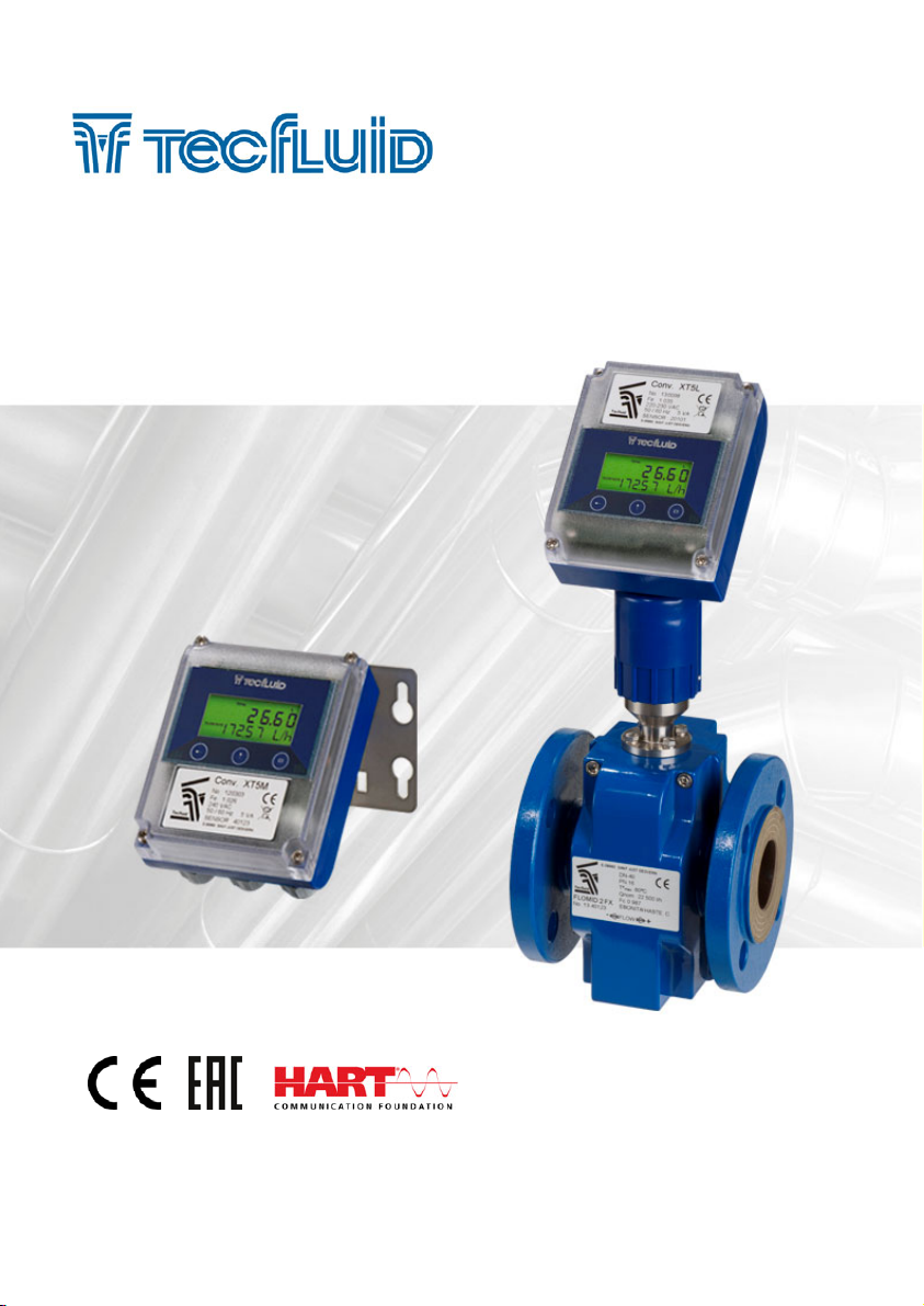
R-MI-FIXT5 Rev.: 3 english version
Series FLOMID
Sensor FLOMID-FX
Converter XT5
Instructions manual
The art of measuring

2
Thank you for choosing a product from Tecfluid S.A.
This instruction manual allows the installation, configuration,
programming and maintenance. It is recommended to read it before
using the equipment.
• This document shall not be copied or disclosed in whole or in any
part by any means, without the written permission of Tecfluid S.A.
• Tecfluid S.A. reserve the right to make changes as deemed
necessary at any time and without notice, in order to improve the
quality and safety, with no obligation to update this manual.
• Make sure this manual goes to the end user.
• Keep this manual in a place where you can find it when you need
it.
• In case of loss, ask for a new manual or download it directly from
our website www.tecfluid.com Downloads section.
• Any deviation from the procedures described in this instruction
manual, may cause user safety risks, damage of the unit or cause
errors in the equipment performance.
• Do not modify the equipment without permission. Tecfluid S.A. are
not responsible for any problems caused by a change not
allowed. If you need to modify the equipment for any reason,
please contact us in advance.
PREFACE
WARNINGS

3
TABLE OF CONTENTS
SENSOR FLOMID-FX
1 WORKING PRINCIPLE .................................................................. 6
2 RECEPTION .................................................................................. 6
2.1 Unpacking .......................................................................... 6
2.2 Storage temperatures ......................................................... 6
3 HANDLING ................................................................................... 7
4 INSTALLATION ............................................................................. 7
4.1 Sensor position .................................................................. 8
4.2 Straight pipe sections ......................................................... 8
4.2.1 Mixtures ................................................................ 9
4.3 Valves ............................................................................... 9
4.4 Pumps ................................................................................ 9
4.5 Aeration ............................................................................. 10
4.6 Reduction of DN ................................................................. 10
4.7 Vibrations ............................................................................ 11
4.8 Magnetic fields .................................................................. 11
4.9 Temperature ...................................................................... 12
5 MOUNTING ................................................................................... 13
5.1 Parallelism .......................................................................... 13
5.2 Gaskets ............................................................................. 13
5.3 Sensor earth connection ..................................................... 14
5.4 Tightening ........................................................................... 15

4
XT5 CONVERTER
1 INTRODUCTION ........................................................................... 16
2 INSTALLATION ............................................................................. 16
2.1 Sensor connection .............................................................. 16
2.1.1 Compact converter ................................................ 16
2.1.2 Remote converter .................................................. 17
2.2 Electrical connection ........................................................... 17
2.2.1 Power supply wiring ............................................... 18
2.2.2 Analog output wiring ............................................... 18
2.2.3 Pulse output wiring ................................................ 20
3 REMOTE SENSOR ......................................................................... 21
3.1 Preparing the cable ................................................ 21
3.2 Cable installation ..................................................... 21
3.3 Cable connection to the sensor ............................... 23
3.4 Cable connection to the converter ........................... 24
3.5 Cable specifications ............................................... 25
4 CONVERTER INTERFACE .............................................................. 26
5 INSTALLATION PARAMETERS ....................................................... 27
5.1 Sensor factor ...................................................................... 27
5.2 Electronic converter factor ................................................... 27
5.3 Nominal diameter ................................................................. 28
5.4 Measuring units .................................................................. 28
5.5 Mains frequency ................................................................. 28
6 CONVERTER PROGRAMMING ...................................................... 29
6.1 Decimals for the flow rate indication ..................................... 29
6.2 Current output (4-20 mA) configuration ................................ 29
6.3 Pulse output ....................................................................... 30
6.4 Cut off ............................................................................... 30
6.5 Damping ............................................................................ 30
6.6 Flow direction ................................................................. 32
6.7 Empty pipe ......................................................................... 32
6.8 Zero drift adjustment ........................................................... 32

5
7 SERIAL NUMBER AND FIRMWARE VERSION ............................... 33
8 EMPTY PIPE INDICATION ............................................................. 33
9 RESET ......................................................................................... 33
10 KEYBOARD DISABLE AND ”WRITE PROTECT” ............................. 33
11 CHANGING THE POSITION OF THE DISPLAY ................................ 34
12 HART COMMUNICATION .............................................................. 34
13 EXAMPLES OF USEFUL CALCULATIONS ...................................... 35
13.1 Measurement error correction ............................................. 35
13.2 Configuration of pulses / unit of volume .............................. 36
14 TECHNICAL CHARACTERISTICS .................................................. 37
15 MAINTENANCE ............................................................................ 38
15.1 Fuse ................................................................................... 38
16 SAFETY INSTRUCTIONS ............................................................... 39
16.1 Pressure equipment directive .............................................. 39
16.2 Certificate of conformity TR CU (EAC marking) ..................... 39
17 DIMENSIONS ............................................................................... 40
18 TROUBLESHOOTING ................................................................... 52
19 PROGRAMMING DIAGRAM ........................................................... 53
ANNEX A Flow rate table ...................................................................... 55
6
SENSOR FLOMID-FX
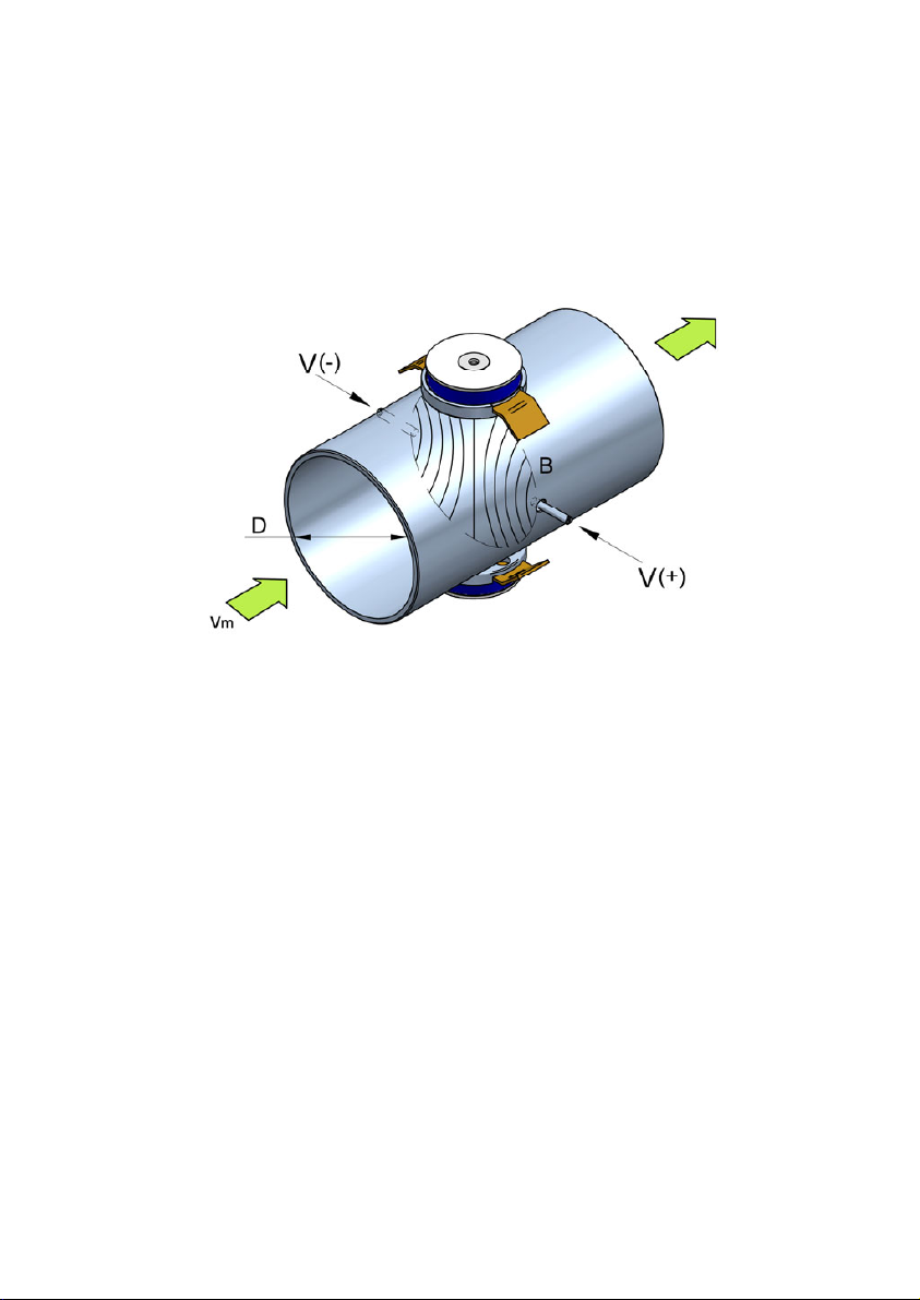
1WORKING PRINCIPLE
The FLOMID electromagnetic flowmeters are based on Faraday’s induction law.
When an electrically conductive liquid flows through a magnetic field, perpendicular to the
flow direction, it induces a voltage V proportional to the liquid velocity.
Two electrodes in contact with the liquid and positioned perpendicularly to the magnetic
field, sense this voltage V.
2 RECEPTION
The FLOMID electromagnetic flowmeters are supplied conveniently packaged for their
protection during transportation and storage, together with their instructions manual for
installation and operation.
All the instruments are supplied tested in our flow rigs, obtaining the gain factor Fc of each
sensor.
2.1 Unpacking
Unpack the instrument carefully, removing any remains of the packing from the inside of the
sensor. Do not remove the grease from the neck that couples to the electronics housing.
2.2 Storage temperatures
Sensors linings of: PTFE and PVDF -20ºC ...... +60ºC
PP and EBONITE -5ºC ...... +50ºC
V = B·vm·D
Where:
V = Measured voltage in the electrodes
B = Magnetic field
vm= Average liquid velocity
D = Pipe diameter
7
4 INSTALLATION
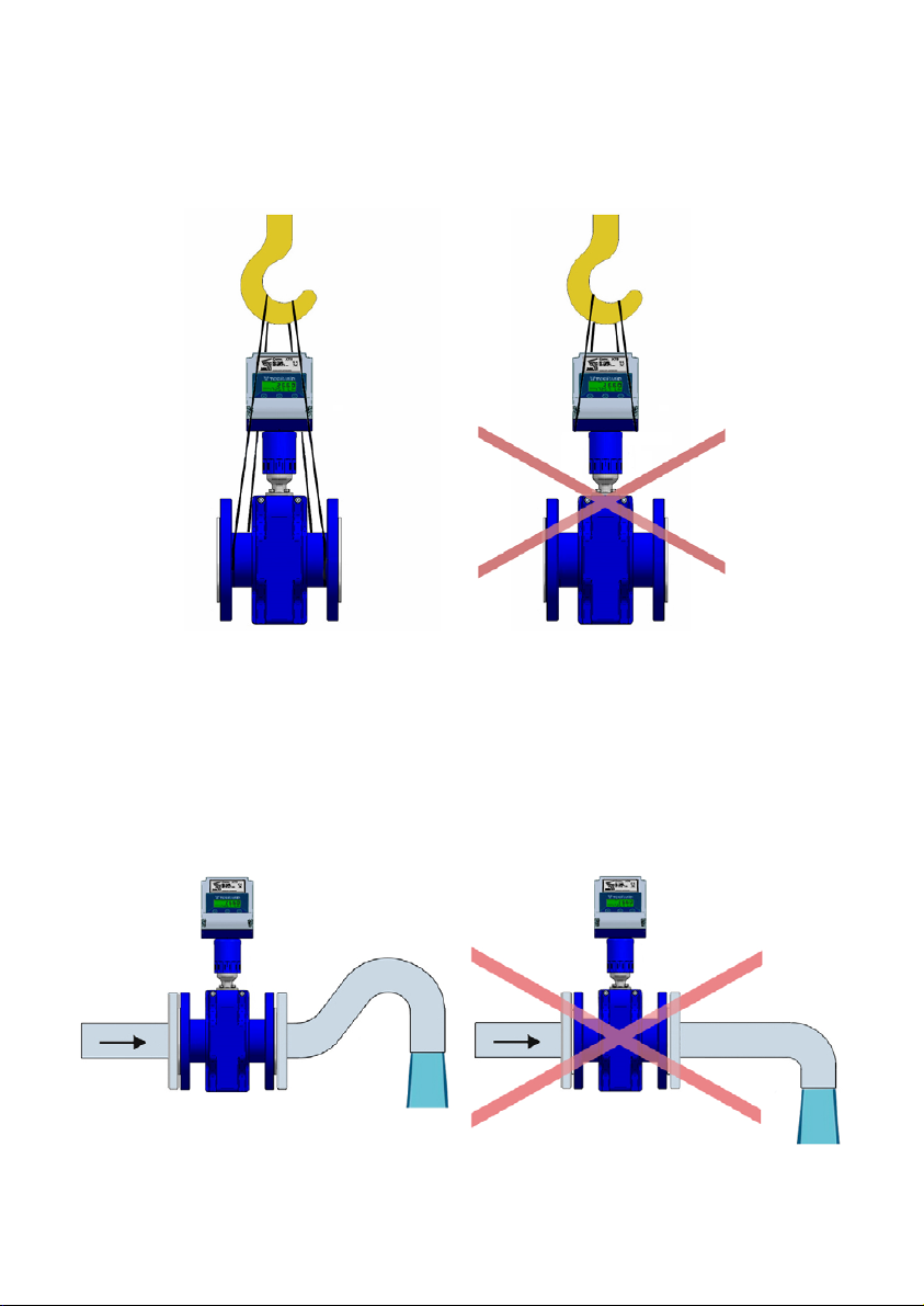
This should be made in a point that guarantees that the pipe is always completely full.
Avoid high points of the pipes where air pockets usually form, or pipes with falling flow where
vacuums can form.
Partially full pipes can produce important reading errors.
Flow rate measurement with open discharge makes it necessary to install the flowmeter in a
pipe section with a siphon which avoids stagnation of air in the sensor.
3 HANDLING
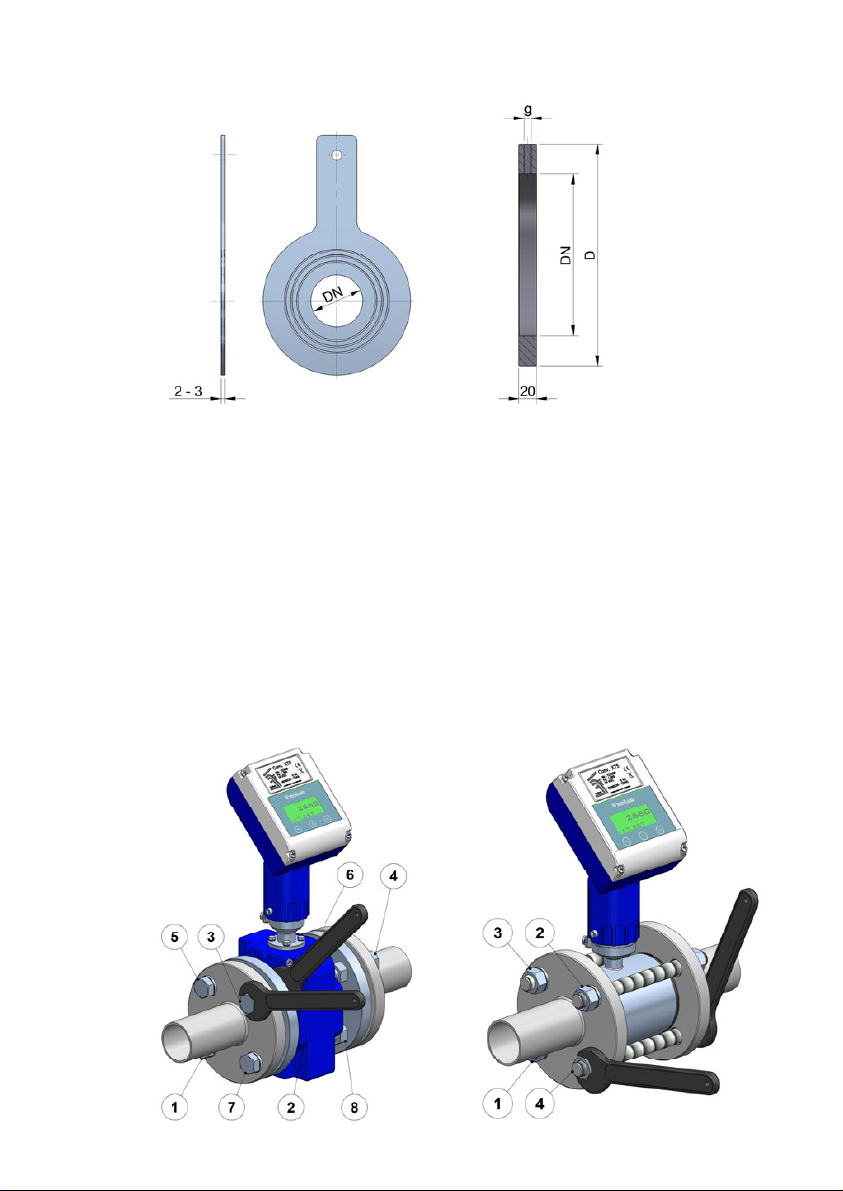
It should always be done with care and without knocks.
The large diameter sensors have rings for holding the elevation elements. If the flowmeter is
held using slings, these should hold on the sensor and not on the electronics housing (see
drawing).

8
4.2 Straight pipe sections
They are necessary before and after the sensor. The minimum distances are the following:
Upstream 5 DN
Downstream 3 DN
In installations with turbulent flow it may be necessary to increase these distances.
4.1 Sensor position
The most adequate position is with the electrodes in a horizontal plane. In this way,
deposits of particles on the electrodes are avoided.
9
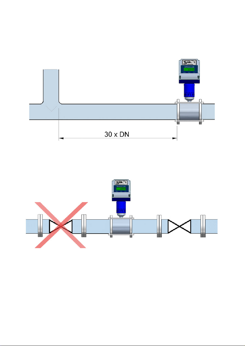
4.2.1 Mixtures
If liquids of different conductivities are mixed it is necessary to install the sensor a minimum
of 30 DN from the point of mixture in order to obtain a uniform conductivity of the liquid and
stabilize the readings.
If this distance is shorter, readings may be unstable.
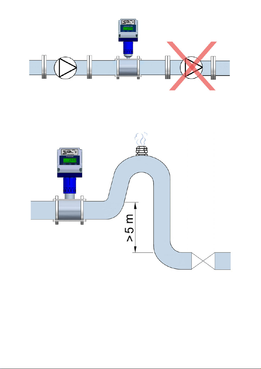
4.4 Pumps
Pumps should be mounted upstream from the sensor to avoid the suction of the pump
(vacuum) that could damage the sensor liner.
4.3 Valves
Control valves or shut-off valves should always be installed downstream from the sensor to
assure that the pipe is always full of liquid.
10
4.5 Aeration
If there is a point where the level difference is higher than 5 m an air inlet valve should be
installed after the sensor to avoid a vacuum effect that could damage the sensor liner.
4.6 Reduction of DN
In installations where, due to reasons of the flow rate to be measured, a sensor of a smaller
DN than the pipe DN must be mounted, the reduction must be done with an angle smaller
than 4º to avoid turbulences that can give false readings.
If the angle cannot be so small, straight pipe sections indicated in 4.2 point must be kept.

11
4.7 Vibrations
Vibrations of the pipes should be avoided by anchoring the pipe before and after the sensor.
The vibration level should be less than 2.2 g in the range of 20 -150 Hz according to IEC 068
-2-34.
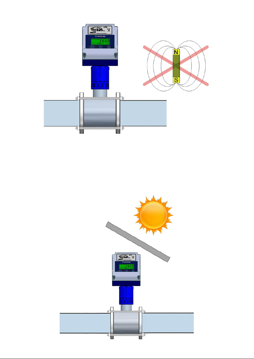
4.8 Magnetic fields
Strong magnetic fields close to the sensor should be avoided.
12
4.9 Temperature
In open air installations it is recommended to install a protection to avoid direct sun light on
the flowmeter.
With thermally insulated pipes DO NOT insulate the sensor. High temperatures can damage
it.
The maximum liquid temperatures are shown on point 14 of page 37.
13
5 MOUNTING
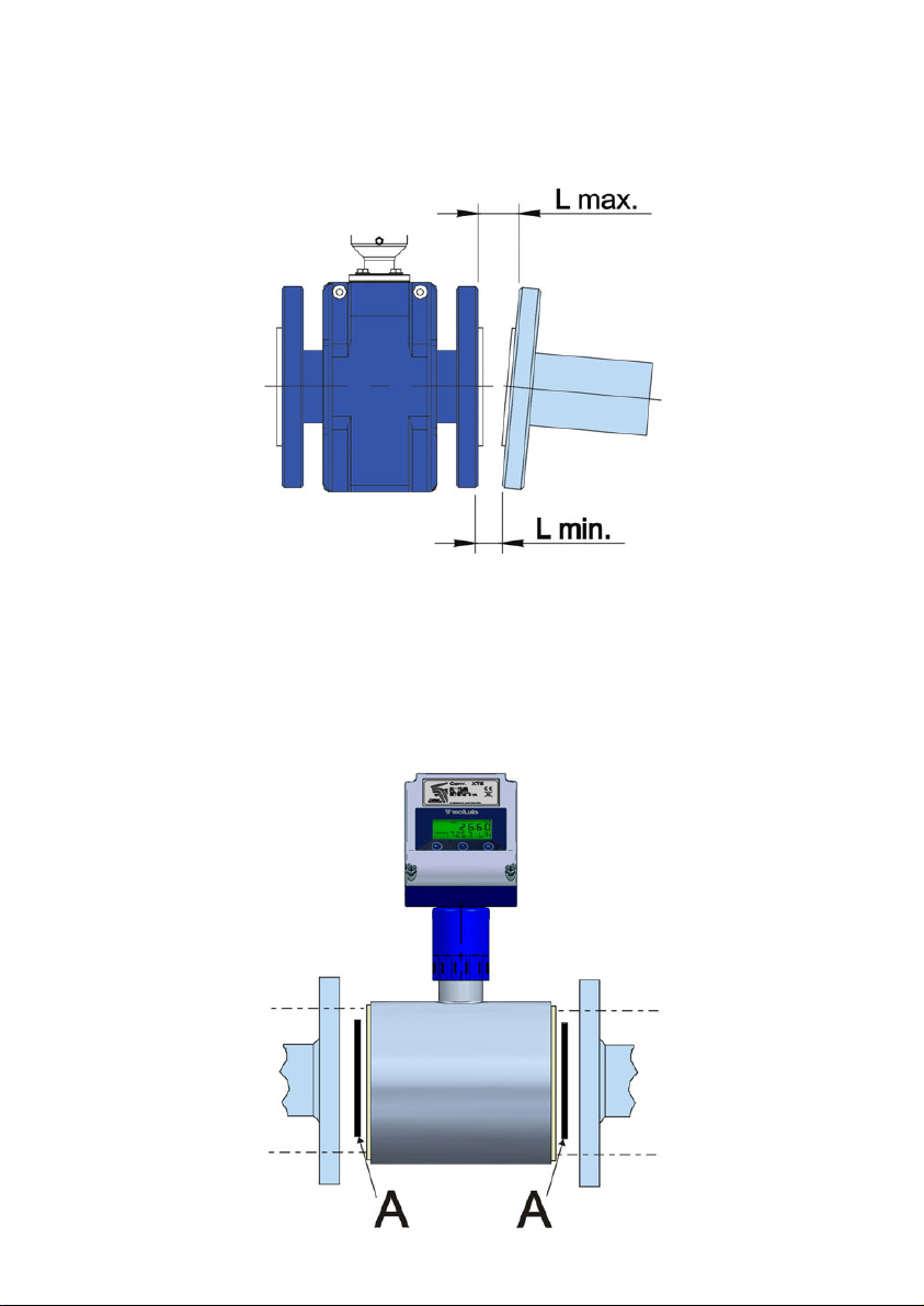
5.1 Parallelism
The maximum parallelism error must be less than 0.5 mm (Lmax—Lmin ≤ 0.5 mm).
5.2 Gaskets
In the wafer sensors, to avoid leakage of liquid inside the sensor, it must be ensured that the
rubber gasket (A) of the figure is well centered, so that it presses directly on the plastic of the
sensor.
The standard material of the supplied gasket is NBR. Other materials can be supplied on
demand.
The sensors for connection other than wafer, are supplied without gaskets.
14
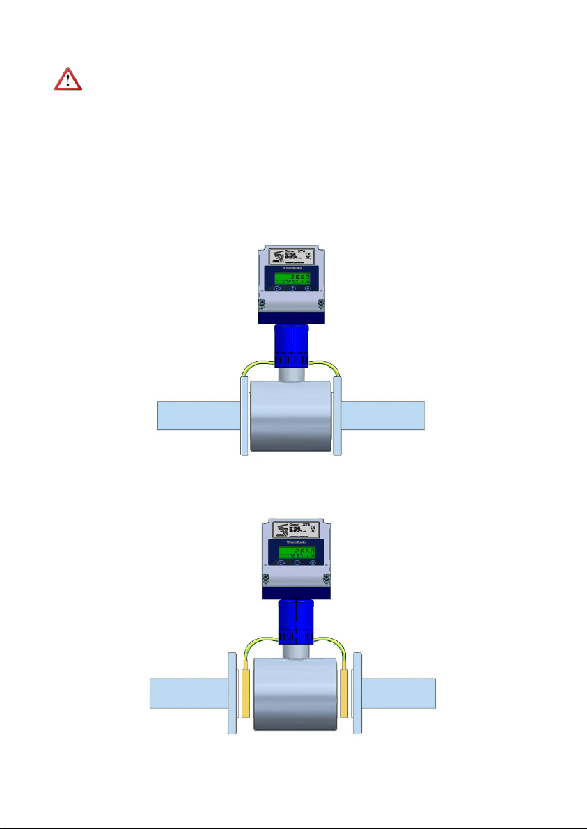
5.3 Sensor earth connection
To obtain correct operation the sensor should have its functional earth connected to a point
that is in direct contact with the liquid whose flow rate wants to be measured.
The earth cables should assure a good electrical contact. To obtain this, they should be well
screwed down and with a good contact on both sides of the sensor. It is important to
eliminate paint or coverings that act as insulation of the connection.
The functional earth connection should be used exclusively for the sensor given that parasitic
signals caused by other electrical equipment connected to this earth can cause malfunction
of the sensor.
The connection of the functional earth should be made as follows:
a) In the case of metallic pipes without internal lining connect the earth cables to the
counter flanges.
b) In the case of metallic pipes with internal lining or plastic pipes, connect the earth
cables to the earthing rings, supplied on request.
The earthing rings are necessary when installing in non-metallic pipes or in metallic pipes
with internal insulating liner (PTFE, PVDF, PP, EBONITE, etc.).
15
Earthing rings are supplied in two versions:
Metallic, disk in stainless steel EN 1.4404 (SS 316L), for liquids compatible with this material.
Plastic, with an electrode to make the contact with the liquid. The materials (plastic and
metal) depend on the working liquid.
5.4 Tightening
The tightening torque of the fastening screws of the flanges should not exceed 32 Nm for
maximum working pressures of 16 bar.
This tightening torque is applicable for wafer sensors (FLOMID-0FX), and with flanges
(FLOMID-2FX) for a pressure value of 16 bar.
The maximum value of the torque depends on the sensor nominal pressure (PN).
The tightening of the flange bolts should be done uniformly, following the sequence indicated
in the drawings according to the number of flange bolts.
PlasticMetallic
Dimensions in mm

16
XT5 CONVERTER
1 INTRODUCTION
The XT5 converter unit can be used with the different FLOMID and FLOMAT series of
electromagnetic flow sensors. The electronic circuit is based on the most advanced
technology, in order to obtain accurate and reliable measurements.
The device provides the following features:
• Coil excitation by means of pulsed signal to obtain a negligible zero offset.
• Pulse and analog current outputs proportional to the flow rate and user
configurable.
• Local and separate mounting.
• Easy interchangeability with other sensors.
• Display orientable 180º to adapt to the installation position.
• HART protocol compatibility (XT5H model).
2 INSTALLATION
2.1 Sensor connection
2.1.1 Compact converter
The converter provides two cables to be connected to the sensor. Once connected, slide
the converter along the sensor neck until the stop. Tight the two fixing screws.
Fixing
screws
Neck
Connectors

17
2.1.2 Remote converter
One of the ends of the cable has a header and two wires, to connect them to the sensor.
The connection is as explained in point 2.1.1.
The other end has to be connected to the converter, and has five wires. The cable must be
passed through the cable gland and the connection for each wire is explained in chapter 3.
2.2 Electrical connection
For the electrical connection, the XT5 has two screw terminal strip. To help in the connecting
of the equipment, the description of the terminals is marked on the printed circuit.
For the electrical installation it is recommended to use multiple conductor cables with
individual cable sections in the order of 0.25 to 0.5 mm2in order to make it easier to
connect. It is better to maintain the cables with mains voltage (power supply) separated from
the cables with low level signals (4-20 mA, etc.).
Before starting the installation, check that the PG11 cable glands are the right size for the
cables to be used, in order to guarantee the instrument will stay watertight. The cable glands
used are for cables with outside diameters between 3.5 mm and 10 mm.
To connect them, peel the outside insulation to free the inner cables. It is recommended to
tin the ends of the wires to avoid loose ends. Pass the cables through the cable glands and
screw down in the corresponding positions of the terminal strip. Once the wiring is finished
make sure that the cables are well gripped by the cable glands to maintain the degree of
protection.
Incorrect installation of the cable gland or inadequate cable placement can cause irreparable
damage to the converter.
IMPORTANT NOTE: In order to comply with the electrical safety requirements as per EN-
61010-1 (IEC 1010-1), the installation of the equipment must take into account the following:
• A mains switch must be provided to disconnect the equipment. This switch must
be marked as the disconnecting device for the equipment and be within easy reach
of the operator.
• The mains supply must have an earth line.
• The housing must not be opened when the instrument has mains supply
connected.
IMPORTANT NOTE: To ensure proper operation of the equipment, it is recommended to
make the connection paying attention to the following points:
• For the output signals, use shielded cable when possible.
• Keep the cables away from strong sources of noise.
18
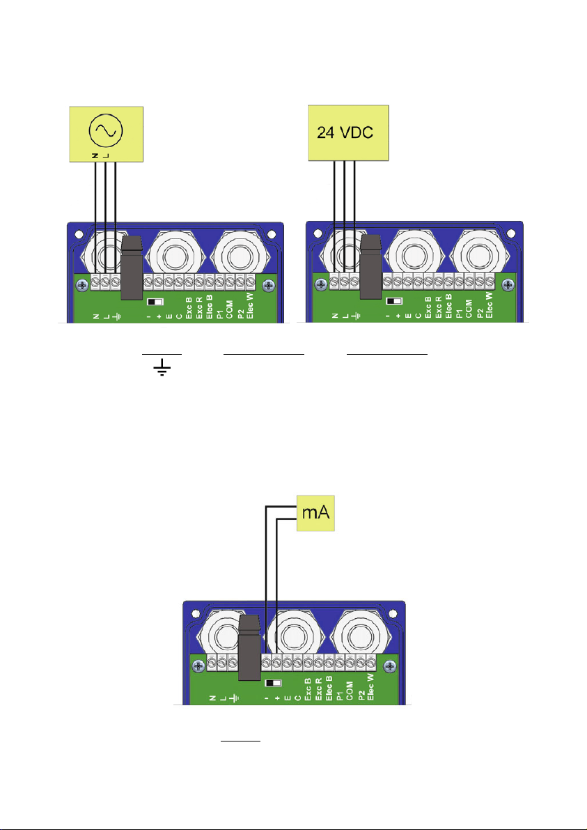
2.2.1 Power supply wiring
Before connecting the converter, check that the supply voltage available is the same as
marked on the label of the instrument.
Terminal
+mA (positive)
-mA (negative)
Terminal AC power supply DC power supply
Earth Earth
NNeutral 0 V
LPhase 24 V (+)
It is important to connect the mains earth to the instruments with AC power supply due to
the presence of a mains filter inside that requires this connection.
2.2.2 Analog output wiring
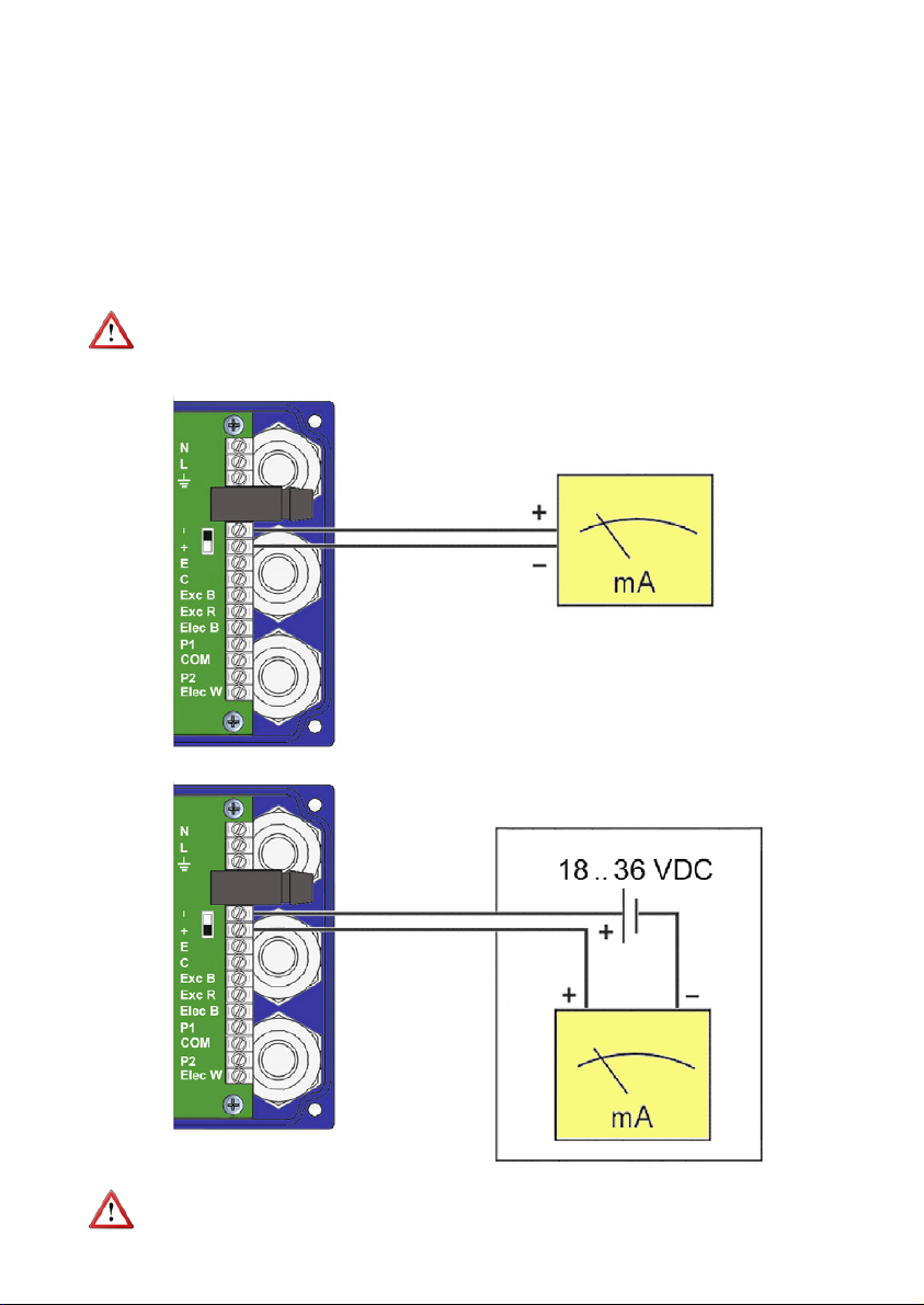
19
NOTE: Never connect the load between terminals + and –. The analog output could be
damaged.
The analog output is galvanically isolated. It can be either active (that means the receptor
must be passive) or passive (that means the receptor must supply the power for the current
loop). It is recommended to use a receptor with an input resistance of less than 700 Ω to
guarantee correct operation.
To configure the analog output type (active or passive) there is a slide switch situated just
behind the terminal strip. For the passive mode the switch must be towards the positive
terminal and for active mode the switch must be towards the negative terminal. To move the
switch use the point of a small screwdriver.
In the case of using HART communication the output mode should be passive. Normally a
HART master is active.
NOTE: The analog output has protection against reversed polarity. Due to another
protection against over voltages, if a loop supply voltage of greater than 32 V is connected
the equipment may be damaged.
ACTIVE MODE
PASSIVE MODE
20
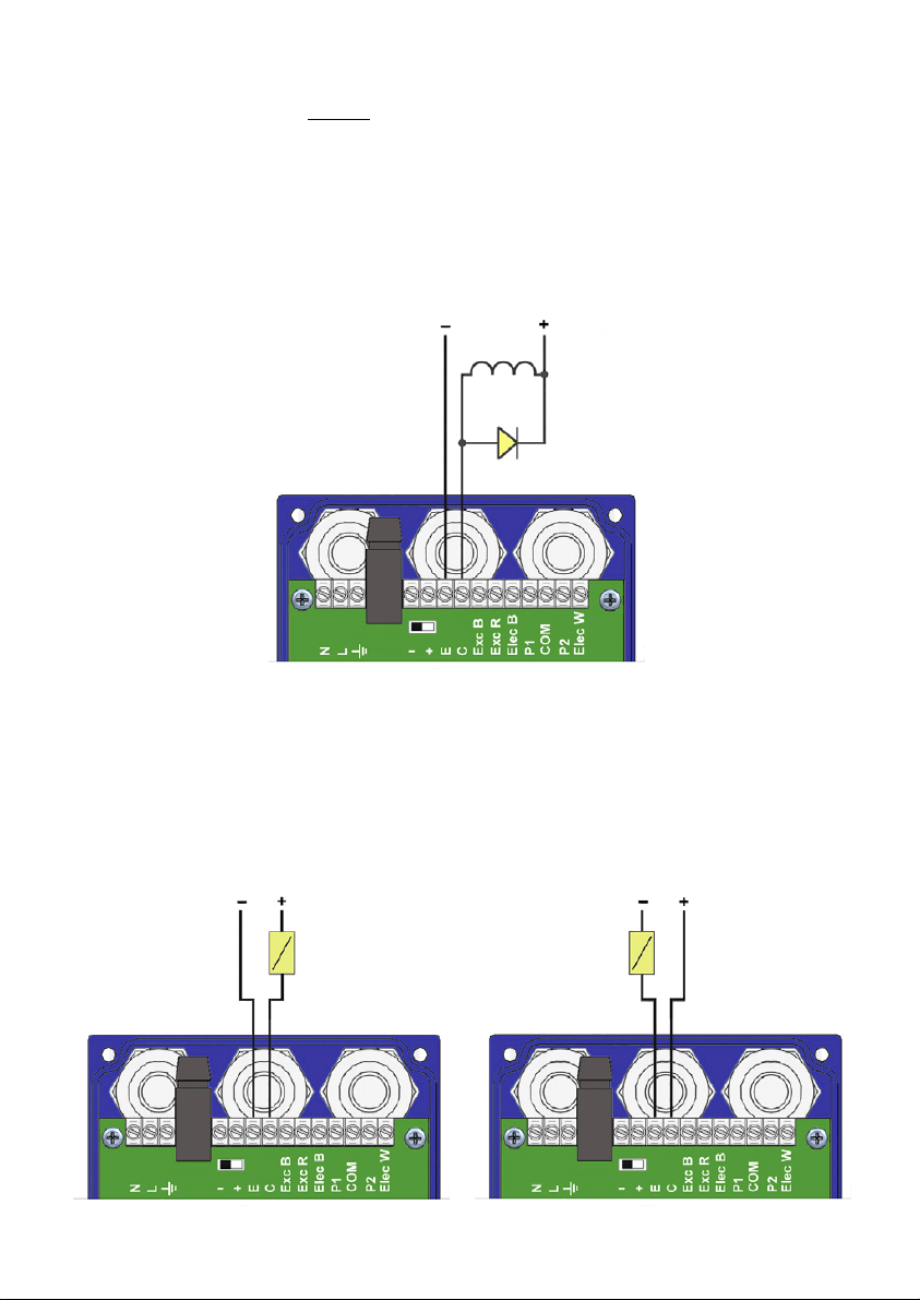
2.2.3 Pulse output wiring
Terminal
EEmitter
CCollector
The pulse output is opto-isolated. The terminals are the collector and emitter of an NPN
bipolar transistor.
In the case of using inductive loads, in order to protect the output transistor, the use of free
wheeling diodes is required.
Connection examples
The two usual ways to connect the alarm outputs are NPN or PNP modes, depending on if the
load is connected to the positive or negative terminal.
In the following figures, an example of connection for the alarm 2 in NPN and PNP mode can
be seen.
PNP connectionNPN connection
Other manuals for FLOMID Series
2
This manual suits for next models
2
Table of contents
Other Tecfluid Accessories manuals

Popular Accessories manuals by other brands

D-Link
D-Link mydlink DCH-S160 user manual

Amphenol
Amphenol Telaire Ventostat T8100 NS Series User instructions

ParTech
ParTech SoliTechw2 IR Series instruction manual

PFlow Industries
PFlow Industries 21 Series owner's manual

Beko
Beko BLSD3577 Instructions for use

SABINE
SABINE ZIPBEAT 3000 operating instructions


novotechnik
novotechnik LWH Series user manual

FRONIUS
FRONIUS OPT/i WF R installation instructions

Silvercrest
Silvercrest SPB 2.6 A1 User manual and service information

MaxiCosi
MaxiCosi Shape of You Instructions for use

C.P. Electronics
C.P. Electronics SPIR-F installation guide

MasterChef
MasterChef TheTV Series quick start guide