manuals.online logo
Brands
  1. Home
  2. •
  3. Brands
  4. •
  5. TECHLIGHTING
  6. •
  7. Lighting Equipment
  8. •
  9. TECHLIGHTING T-trak 700TTSCCADJ Series User manual

TECHLIGHTING T-trak 700TTSCCADJ Series User manual

1.8
Installation Instructions for
Adjustable Standoff With Conductive Connector 700TTSCCADJ_
1
920TTSADC
GENERAL PRODUCT INFORMATION:
This product is suitable for indoor dry locations only.
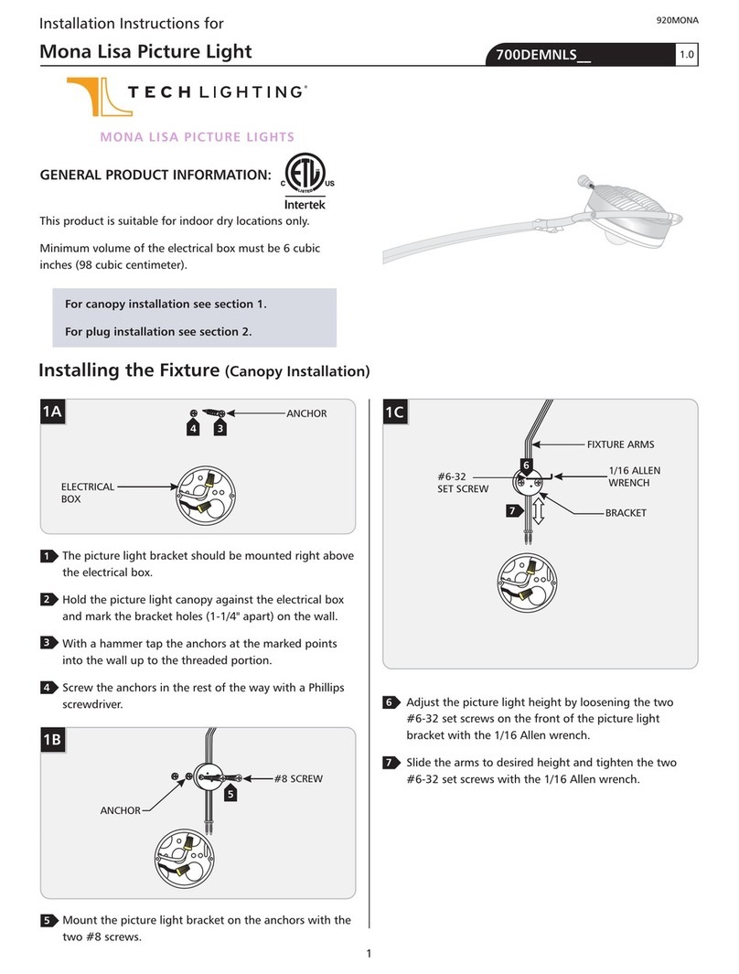
Use the adjustable standoffs every four feet of a Single-
Circuit T~trak™ run.
SPECIAL INSTALLATIONS
Install the Standoff
5/64" ALLEN WRENCH
STANDOFF POST #8-32 SET SCREW
CABLE POST
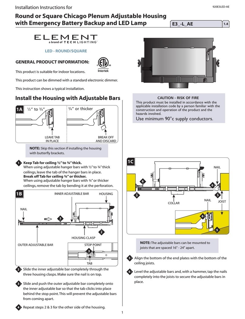
Remove the #8-32 set screw with the provided 5/64"
Allen wrench.
Remove the cable post from the standoff rod.
Mark the standoff location points onto the ceiling.
Tap the anchor at the marked point into the ceiling up
to the threaded portion with a hammer.
1B
ANCHOR
CEILING
ANCHOR
Screw the anchor in the rest of the way with a Phillips
screwdriver.
STANDOFF POST
#8 SCREW
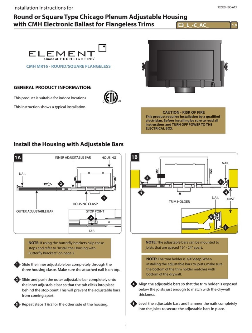
Fasten the standoff post to the anchor by inserting the
provided #8 screw through the standoff post and
screwing it to the anchor.
T ~ t r a k TM
1A
1
2
1
2
3
4
4
3
1C
5
1D
6
5
6
US
C
CM
5/64" ALLEN WRENCH
STANDOFF POST #8-32 SET SCREW
CABLE POST
2
Push the tab down on the wire grip and feed the
aircraft cable through the wire grip post.
Pull the aircraft cable through the hole on the wire grip
post to adjust the standoff height.
Release the tab to lock the standoff in position.
TAB
AIRCRAFT CABLE
WIRE GRIP
NOTE: The two provided plastic inserts are not used
in this procedure.
BOTTOM #4-40 SCREW
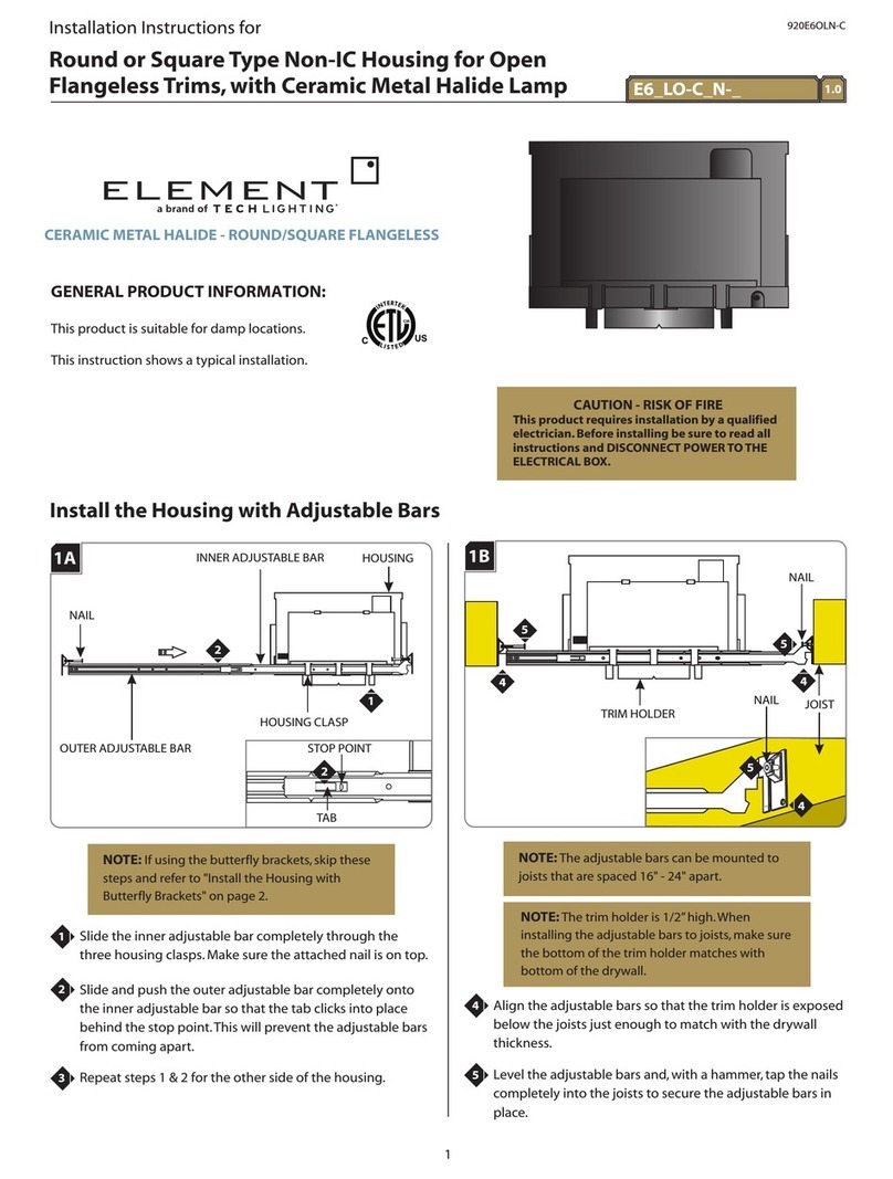
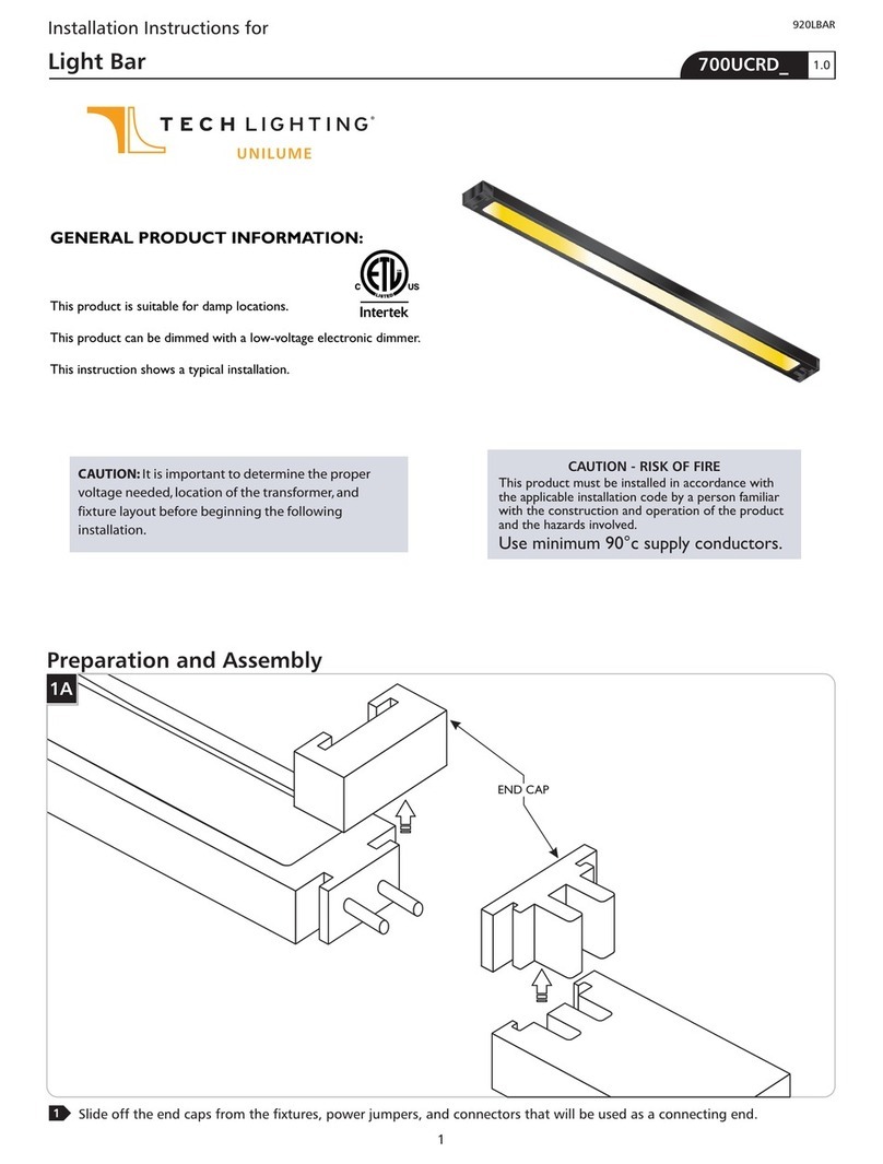
Push a Single-Circuit T~trak section all the way into the
conductive connector with its white side up.
Tighten the bottom #4-40 screw with a Phillips
screwdriver for a proper power connection.
Repeat steps 1 & 2 for the other Single-Circuit T~trak
section.
Cut the excess aircraft cable for a nice and neat look
with a sharp cutter after leveling all standoffs to the
desired height.
CONDUCTIVE
CONNECTOR
Mount the Single-Circle T~trak™ to
the Standoff With Conductive
Connector
THE OTHER
SINGLE-CIRCUIT
T~TRAK SECTION
ONE SINGLE-CIRCUIT
T~TRAK SECTION
WHITE SIDE
GRAY SIDE
WHITE SIDE
GRAY SIDE
NOTE: When the Single-Circuit T~trak is formed
into a shape, the ends become staggered. The
staggered ends have to be cut even with a
hacksaw. Refer to the Single-Circuit T~trak
instructions to trim the ends before proceeding
with these steps.
1E
Push the cable post completely into the standoff post.
Align the cable post hole with the standoff post hole
and replace the #8-32 set screw.
Tighten the #8-32 set screw with the 5/65" Allen
wrench.
7
8
9
7
8
9
1F
10
11
12
10
11
2A
1
2
3
4
1
24
WHITE SIDE
GRAY SIDE
SINGLE-CIRCUIT T~TRAK
HOUSING
PLASTIC INSERT
PLASTIC INSERT
3
Place one of the provided plastic inserts (with open
section facing up) all the way into bottom of the
housing.
Place the Single-Circuit T~trak into the housing. Make
sure that the Single-Circuit T~trak white insulator is
facing up toward the ceiling.
Push the other plastic insert (with open section facing
down) onto the Single-Circuit T~trak.
3B
SPECIAL INSTALLATION:
Converting the Standoff
NOTE: In the event that the standoff cannot be
located directly above the conductive connector,
the following steps will allow for the standoff
to be installed in close proximity to the
conductive connector while still providing
support and a connection between Single-
Circuit T~trak sections.
Follow the "Install the Standoff " steps on pages 1 & 2.
Unscrew the housing nipple from the housing by
turning the housing nipple counterclockwise.
Remove the housing and the conductive connector from
the housing nipple.
Remove the conductive connector from the housing.
NOTE: In case of cross threading, unscrew the
housing from the housing nipple and repeat step 8.
Tighten the housing nipple to the housing by screwing
the housing nipple clockwise. Make sure not to cross
thread.
1
HOUSING
HOUSING NIPPLE
3A
HOUSING NIPPLE
HOUSING
CONDUCTIVE
CONNECTOR
1
2
3
4
2
3
4
5
6
7
5
7
6
3C
8
8
4
Look inside the conductive connector and make sure
that the white insulator is facing up toward the ceiling.
Push the conductive connector onto the end of one
Single-Circuit T~trak section and tighten the bottom
#4-40 screw with a Phillips screwdriver for proper
power connection.
ONE SINGLE-CIRCUIT
T~TRAK SECTION
BOTTOM #4-40 SCREW
CONDUCTIVE
CONNECTOR
WHITE SIDE
GRAY SIDE
Push the other Single-Circuit T~trak section into the
other end of the conductive connector and tighten the
bottom #4-40 screw with a Phillips screwdriver for
proper power connection.
Cut the excess aircraft cable for a nice and neat look
with a sharp cutter after leveling all standoffs to the
desired height.
1
BOTTOM #4-40 SCREW
CONDUCTIVE
CONNECTOR
1
WHITE SIDE
GRAY SIDE
SAVE THESE INSTRUCTIONS!
3D 3E
THE OTHER SINGLE-CIRCUIT
T~TRAK SECTION
9
10
11
12
7400 Linder Ave.
Skokie, IL 60077
847.410.4400
T ~ t r a k TM
a brand of
www.ttraklighting.com
10 11
12

Other TECHLIGHTING Lighting Equipment manuals

TECHLIGHTING tiella Sola Pack Instruction Manual

TECHLIGHTING

TECHLIGHTING tiella Sola Pack Instruction Manual

TECHLIGHTING ELEMENT E6_LO-C_N Series User manual

TECHLIGHTING

TECHLIGHTING ELEMENT E6_LO-C_N Series User manual

TECHLIGHTING Cirque Small 700CQS User manual

TECHLIGHTING

TECHLIGHTING Cirque Small 700CQS User manual

TECHLIGHTING Mona Lisa User manual

TECHLIGHTING

TECHLIGHTING Mona Lisa User manual

TECHLIGHTING ELEMENT E3-L AE Series User manual

TECHLIGHTING

TECHLIGHTING ELEMENT E3-L AE Series User manual

TECHLIGHTING UNILUME 700UCRD Series User manual

TECHLIGHTING

TECHLIGHTING UNILUME 700UCRD Series User manual

TECHLIGHTING Element CMH MR16 User manual

TECHLIGHTING

TECHLIGHTING Element CMH MR16 User manual

Popular Lighting Equipment manuals by other brands

SGM Regia 2048 user manual

SGM

SGM Regia 2048 user manual

Aihomestyle QS-PLT595X595 Installation and instruction manual

Aihomestyle

Aihomestyle QS-PLT595X595 Installation and instruction manual

Seto ALDEBARAN GLADIUS 2K LED Instructions for use

Seto

Seto ALDEBARAN GLADIUS 2K LED Instructions for use

Marq Haze 800 DMX Service manual

Marq

Marq Haze 800 DMX Service manual

STKR FUL PRO LIGHT TELESCOPING 12679 quick start guide

STKR

STKR FUL PRO LIGHT TELESCOPING 12679 quick start guide

Elation KL FRESNEL 8 FC user manual

Elation

Elation KL FRESNEL 8 FC user manual

IN HOUSE LED ENGU10NR user manuel

IN HOUSE LED

IN HOUSE LED ENGU10NR user manuel

Pelican 9440 user manual

Pelican

Pelican 9440 user manual

Blizzard Lighting Torrent Xray user guide

Blizzard Lighting

Blizzard Lighting Torrent Xray user guide

Pixapro GLOWPAD 112CB user manual

Pixapro

Pixapro GLOWPAD 112CB user manual

IKEA NAVLINGE manual

IKEA

IKEA NAVLINGE manual

Analog way ORCHESTRA user manual

Analog way

Analog way ORCHESTRA user manual

Aladdin BI-FABRIC 4 user manual

Aladdin

Aladdin BI-FABRIC 4 user manual

LOUVERS LED Talon installation instructions

LOUVERS LED

LOUVERS LED Talon installation instructions

MOFLASH SIGNALLING LEDA125-01 Series INSTALLATION & TECHNICAL INFORMATION

MOFLASH SIGNALLING

MOFLASH SIGNALLING LEDA125-01 Series INSTALLATION & TECHNICAL INFORMATION

hillvert HT-WEDGE-50A user manual

hillvert

hillvert HT-WEDGE-50A user manual

Original BTC Hatton 3 instruction manual

Original BTC

Original BTC Hatton 3 instruction manual

Melink ML1SLS20-5MRGBCCT instruction manual

Melink

Melink ML1SLS20-5MRGBCCT instruction manual

manuals.online logo
manuals.online logoBrands
  • About & Mission
  • Contact us
  • Privacy Policy
  • Terms and Conditions

Copyright 2025 Manuals.Online. All Rights Reserved.